Rear Axle Hub/Brake Problems Again!

We don’t seem to be able to escape our problems with the fitment of the rear axle hubs and brake drums. A thorough accounting of the issues we faced were first documented in several videos included in an earlier post:https://valvechatter.com/?p=13569

We thought we had conquered the problems we had encountered with the hub rubbing the axle flange and with the brake drum rubbing against the brake backplate, but upon installing the road wheels and tires we discovered that all had not been corrected! 

The wheel on the left side of the car turned freely but on the right side we found that despite the hub nuts being tightened and torqued to 38 ft. lbs. as directed in the maintenance manual, the wheel and tire wobbled back and forth. It is a little hard to tell but it can be seen in the beginning of the Bugeye Restoration Video Episode Ninety-two. We then tried a pair of brand new Moss Classic Gold brake drums that we had on hand.

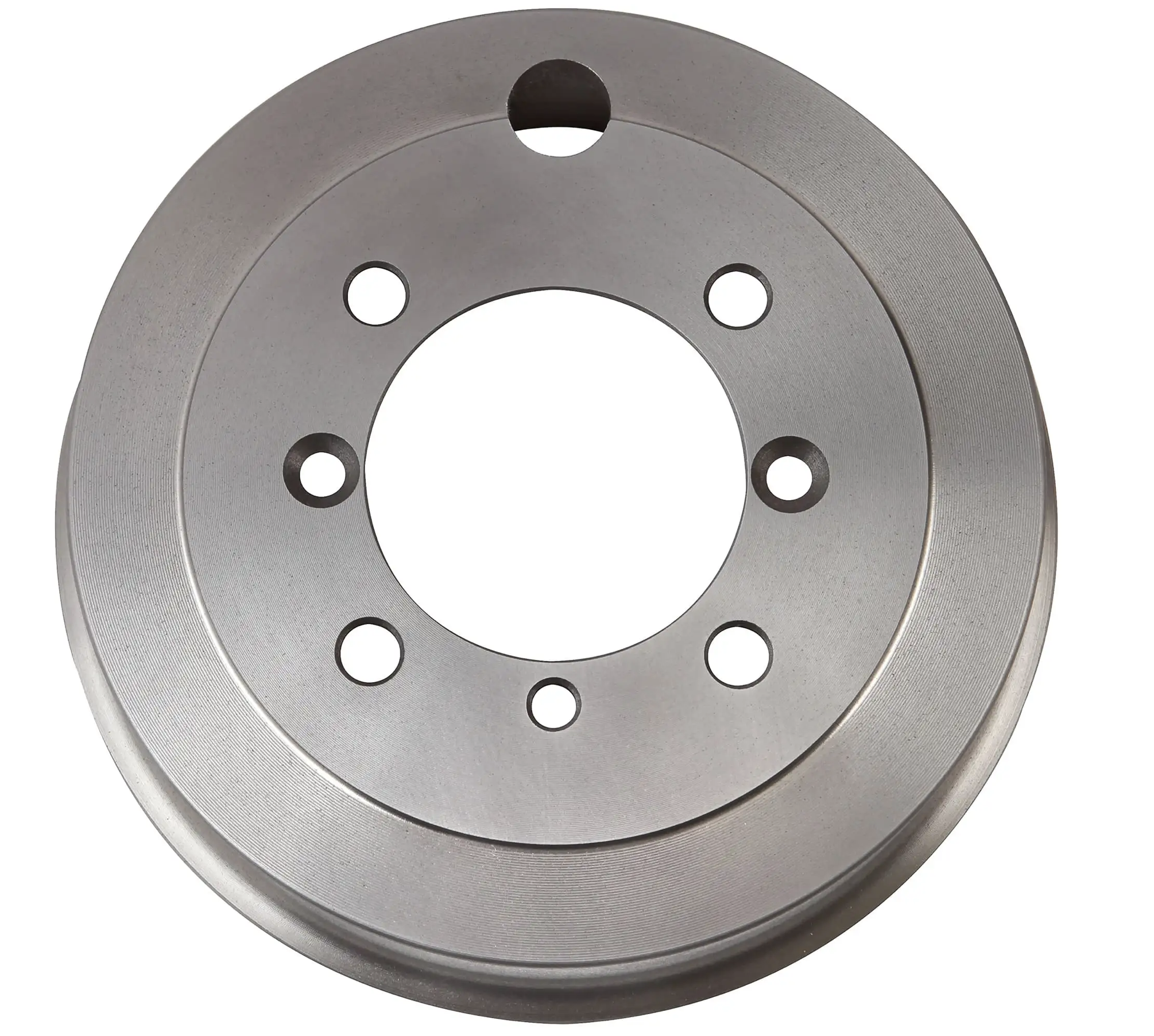
Unfortunately, the new drums rubbed against the backplates just ever so slightly. We visited our friend, Randy Forbes, and he graciously set up his milling machine to remove .0075″ from the back side of each brake drum. We then mounted them on the car and found that we had eliminated the rubbing against the brake back plates, but we still had the dreaded wobble on the RH wheel.

We removed the RH axle half-shaft, bent back the locking tab washer and tightened the hub nut to 145 ft lbs. This actually turned the nut very little but it was sufficient to eliminate the wheel wobble. Not really sure about the mechanics of all of this but we will take it and move on!

All of this trial and error is shown in the Bugeye Restoration Episode Ninety-two video

https://vimeo.com/1050905261/b7432414cf?share=copy

We will now machine the edges of the drums and see if we can end up with a fully operational axle assembly. Stay tuned….


Flywheel and Clutch

In 2022 when we pulled the engine from the car to begin the restoration, the clutch was working just fine. However, with the engine out of the car and the gearbox already separated from the engine, It seemed the perfect time to go ahead and replace the clutch disc and pressure plate (cover) with new components. We have learned on multiple occasions that just because a part is new doesn’t mean it is better, but the clutch is definitely a wear item so we decided to buy a new disc from Rivergate and a new Borg & Beck pressure plate from A.H. Spares. We had already observed that the ring gear was pretty chewed up so we ordered a new one from A.H. Spares as well.

Upon removing the clutch and flywheel from the engine we noticed that we did have wear on the flywheel surface so we decided to go ahead and have it resurfaced. That was work was done by Southwest Hydraulic, 177 Jackson Rd, Venice, FL 34292 (941) 786-8530. We then took the flywheel, new ring gear and clutch assembly to VAMI – Venice Auto Marine Engine Machine Shop 331 Camion St. Venice Fl. 34285 (941) 484-2474 to have the ring gear replaced and the complete assembly dynamically balanced.

One VERY POSITIVE by-product of removing the flywheel was the discovery that not only had the crank rear seal, installed at the time we purchased the rebuilt 1275 engine from Rivergate, not leaked at all, the entire backplate was still pristine.

No leaks – Rear Crank Seal

Bugeye Restoration Video Episode Sixty-five https://vimeo.com/952645430/164949ac19 provides documentation of the removal of the clutch and flywheel as well as the installation of the new clutch.

These are the Borg & Beck installation instructions:

Borg & Beck Clutch Installation


Engine Electrical Components

Gear Reduction Starter

We have gone back and forth between using the Lucas starter with the Bendix that engages from the rear of the ring gear and the modern gear reduction starter that engages from the front of the flywheel.We have currently replaced the starter with a modern gear reduction starter from APT Fast. Unlike the old Lucas starter it cranks until the motor fires. Definitely more difficult to install than the original, but hopefully easier starting will make it worth it. Fastening the lower bolt was accomplished by jacking up the right front, removing the tire and wheel and reaching through the hole in the frame wall. The cranking sound is very different than the Lucas starter, but functionality is substantially improved. We chose to continue to use the old pull starter switch on the dash, but could have hooked up the starter to a modern solenoid as well.

Gear Reduction Starter

Gear Reduction Starter

Alternator 

The only information we have on the alternator is that it is a rebuilt unit designed to replace the Lucas alternator that we had in the car previously. It’s rated output is 65 amps.

Alternator Invoice

Rather than having two bolts for the left and right ears of the alternator, a single long bolt and a stainless bushing have been added to enhance the stability of the mounting.

Bugeye Alternator with new Mounting Bushing


Exhaust

Nothing in our exhaust system is as original! From the header to the oxygen sensor in the exhaust pipe to the dual tip muffler, everything is a modification. We have had the header fitted since the early 2000s. We don’t have a record but we are pretty sure that it was sourced from Mini-Mania and produced by Maniflow in the U.K. The header is a long branch, 1 5/8.” Before we initially installed it we had it Swain-Coated for thermal insulation. While beautiful then, it looks a little tired now so we will send it off to Jet-Hot Coatings to have them refinish it so that it will match our intake manifold.

Header

The Jet-Hot coating now matches the intake manifold.

Jet-Hot coated header

We purchased new exhaust pipes and a twin-tipped muffler from Maniflow to fit the header. The pipe comes in two sections. We will be installing a bung in the front pipe for an oxygen sensor to feed our AFR gauge. We also purchased Maniflow’s installation kit which has the hangers and clamps needed to do the job.

Maniflow Exhaust System


Modifying the Rear Leaf Springs

The rear suspension in the Bugeye is comprised of the quarter elliptical leaf springs, the shock absorbers, the radius arms and their mounting boxes, the rebound straps, the rubber bump stops, and of course, the axle. Video Episode Thirteen shows the removal of the original fifteen leaf springs: https://vimeo.com/769992972/c923375ecc

We chose to replace the original springs. The only springs readily available at this time are the 10 leaf “Rally” springs. We ordered a pair from BugeyeGuy.com along with five degree shims that will lower the car to give it a proper ride height. We disassembled these springs, removed the poor paint, cleaned them and repainted with POR-15 and installed teflon tape between each leaf to reduce friction and squeaking. That process is shown in Video Episode Fourteenhttps://vimeo.com/754389824/9ab8550b67

Most of what we have read on the various forums is that the rally spec springs are a bit stiff and don’t give the ride that the original springs provided. Tom Colby of Speedwell Engineering has suggested the removal of three of the leaves to offer an improved ride and we decided to try his suggestion. We can always back up and reinsert the leaves we take out.

Tom Colby’s Spring Modification

Bugeye Restoration Video Episode Sixty-four shows the deconstruction of the springs.https://vimeo.com/989814778/55abef9a4c

It wasn’t quite as easy as just pulling out a few spring leaves. Because the remaining collection of seven springs isn’t as high as the ten leaves, the bolts and springs clasps need to be modified as well. The two 3/8″ hex head bolts (per spring) that are 3 1/4″ long were replaced with two bolts that are 2 1/2″ long. The 5/16″ compressing pins that are 2 1/2″ long were replaced with 5/16″ socket head screws. Socket head screws were used because the compressing pins have round heads that also serve to locate the spring in the chassis spring plate. Rather than rounding the edges off of a hex head bolt the socket head should work just fine.   

Two of the spring clips or brackets are of sufficient size to permit drilling an additional hole in the arms of the bracket to fit the new spring height. There isn’t room on the other two so we will try them as they are or modify at a later date.

The true test will be the ride and that is still months away!


The Doors

Prior to installing the doors on the car, we decided to assemble the door trim. Hopefully this is the best route to take. our first step was to install the rubber door liner that we purchased from Bugeyeguys. This liner is heavy and in addition to providing a solid feel when the door is opened and closed, it should afford a certain degree of sound insulation as well. The liner was glued to the door using contact cement. The photo below shows the finished product:

Rubber door liner installed

That is where the factory stopped. However, we have decided to glue carpet to the rubber liner to give a more finished and coordinated appearance.

Glueing the carpet to the rubber door liner

Carpet installed

We then installed the upholstered door pockets. These also came from Bugeyeguys and they are an upgrade over the originals. These pockets simply slide over the door lip (as can be seen in the photo above) and push down into place. Screws are not required to secure the pockets.

Upholstered Door Pocket

Next came the installation of the polished aluminum cockpit molding. Rubber washers sourced from Bugeyeguys are installed under the thumb screws for the side curtain brackets. They minimize any scuffing that might result from taking the side curtains on and off the car.

Polished aluminum cockpit molding

It was then time to install the door latch mechanism to the door. Four pan head #10-32 x 1/2″ stainless machine screws with internal tooth washers are used to mount the latch to the door.

Door Latch Installation

The final step in the completion of the doors is the installation of the upholstered check straps. These fit through a slot in the door and are then secured to the inside of the “A” pillar of the car. The end of the strap has two metal finishing plates.

Door check strap

With the doors assembly complete it was time to install the door hinges to the car’s “A” pillar. There are two hinges per door. The hinges had been stamped with markings to signify whether the hinge was top or bottom and left door or right door. Each hinge uses three pan head 1/4″-28 x 1/2″ screws and internal tooth lock washers to mount to the car.

Unfortunately, after we mounted the four hinges we decided that there was just too much play in each hinge so we pulled them all from the car and sent them to a hinge repair specialist to install new bushings, washers, and pins so they will be as good as new.

Door hinges

Episode Ninety-one of the Bugeye Restoration Videos shows the installation of the various door components and the mounting of the door hinges.

https://vimeo.com/1034610967/b9737f276b?share=copy

0:00 – Rubber door liner installation

0:44 – Carpet door liner installation

0:56 – Upholstered door pocket installation

1:08 – Door check strap installation

1:16 – Aluminum cockpit molding installation

2:04 – Door latch installation

2:43 – Door check strap finishers

3:05 – Door hinges installed

The restored door hinges were well done with hew bronze bushings and steel pins. There was a little part damage but we were able to touch up the imperfections.  We were able to install the RH passenger door with ease. It seemed to fall into place. We were not so lucky with the LH driver’s door.


Seating

The Bugeye seats were the subject of an earlier post in the restoration section: https://valvechatter.com/?p=14315  This post explains our decision process on the type of seat cover we would use and also reviews the refurbishment of the seat frames and backs.

Geoff Chrysler, owner of Rightway Heritage Trim did a beautiful job with the seat upholstery. We could not have been happier with the leather color or his craftsmanship.

MK2 Seat with inserts and horizontal stitch

The seat tracks were originally screwed to the lower seat frame with 1/4″-28 x 5/8″ flat-head screws, but before long in the production cycle the screws and nuts were replaced with rivets. Several of the rivets in the Bugeye seat tracks were loose and resulted in sloppy seat travel. We decided to drill out the rivets and return to the use of screws and nuts to hold the pieces together. We also sent the seat tracks and rails to Jartex in Forth Worth, TX to have the pieces cleaned and zinc plated. They did a very nice job. We are now ready to assemble the components.

As produced at the time, only the driver’s seat had an adjustable slider track. The passenger seat was bolted in place with four brackets to the floor. However, we also have the adjuster for the passenger seat and will be installing it. It is hard to imagine ever adjusting the seats given how little room there is in the Sprite. They will probably be pushed all the way to the rear and then never moved!

We installed three-point retractable shoulder harnesses and seat belts sourced from Bugeyeguys.com. The belts and their installation were covered in an earlier post which includes a video showing the modifications to the chassis to accommodate the fixing points.https://valvechatter.com/?p=14383

This is the finished product:

The Finished Product

Bugeye Restoration Video Episode Ninety covers the installation of the seat tracks, the retractable seat belts and the seats: https://vimeo.com/1032472964/0a8578978f?share=copy


Accelerator pedal

The accelerator pedal in the Bugeye was mounted on the floor board as seen in the illustration below:

Sprite Accelerator Pedal

We have decided to hang the pedal from the shaft rather than mounting it on the floor and we purchased a kit from Speedwell Engineering that has a throttle return spring so that the mechanism is not dependent upon the throttle plate return spring on the carburetor. 

Episode Eighty-nine of the Bugeye Restoration Videos shows the new pedal arrangement installed in the car:

https://vimeo.com/1029000934/d39495fc82?share=copy

Lighting

Sidelights/Flashers and Tail Lights – We had previously switched the incandescent bulbs in the flasher/side lights and tail lights in favor of LEDs. These are much brighter, consume lower amperage, and produce less heat. This requires replacing the flasher relay can with a substitute suited for LEDs. In our case, the LED flasher relay is incorporated in the Classic Technologies Fuse Box.

License Plate Lights – the original light fixture used two small incandescent bulbs.We converted these to LEDs sourced from Moss Motors.

Headlights – We ordered new headlights from The Bus Depot. Their web site states: “Essentially generic knockoffs of the old Cibie Z-beams, these are tested and certified to meet stringent E-Code and TUV standards.  This means better light distribution and visibility than the cheapo knockoffs sold on Ebay, etc. (which are not E-code and often don’t even come with protective boots on the back). These are direct bolt-on replacements for your stock 7″ sealed-beam headlights; just pop them in and you’re ready to go. They also have curved glass similar to how the sealed-beams looked, whereas most other E-codes have flatter glass that is more common in Europe. (The difference does not affect performance and is just a matter of personal taste, if you care at all.) They also feature a special anti-fogging coating on the insides of the lenses.”

Cibie Headlights

Then we needed to find some LED lights to put in the headlight bodies. After some research we decided on these units from Classic Car LEDs. These were very reasonably priced for what appears to be high quality units.

Classic Car LEDs H4 Mini

Classic Car LEDs

Driving Lights – We have considered, but not decided on, installing Lucas driving lights. Since it is a possibility for the future, the wiring harness has incorporated the wiring for the lights should we desire to add them at a later date. This image shows what they look like once installed.

Lucas Driving Lights


Steering Installation

The steering installation story in the Bugeye has been characterized by fits and starts. This often happens in restorations because systems frequently interfere with the installation of other systems. The new steering rack was first discussed in Bugeye Restoration Video Episode Thirty-five: https://vimeo.com/810655660/46123c8339?share=copy The steering rack is a new one purchased from AH Spares. Information related to the steering rack begins at the 5:00 minute point of the video.

Bugeye Restoration Video Episode Eighty-seven shows the installation of the steering components of the car.

Bugeye Steering Components

We almost missed the shim that fits between the chassis crossmember and the passenger side of the steering rack bracket, part number 44 in the diagram above. This shim aligns the steering column through the dash at the correct angle. We sourced a new one from AH Spares.

The trickiest part of installing the steering system was the coordination required with the installation of the dash. We installed the column through the firewall and let it hang loose. We then positioned it through the hole in the dash and gradually moved both the column and dash upward and into position on the car. Only then did we begin to connect the various components of the steering system. The horn cone was installed with its three mounting screws, but with plenty of room to move around as the column shifted position. All parts were loosely fitted to ensure that we didn’t have any binding of the parts as they were assembled.

Dash with zip ties to the body and column in position

In our final installation we had already centered the steering rack and had also threaded the new tie rod ends to the proper location to hopefully result in a rough alignment of the wheels permitting us to roll the car around in the garage. We will find out later if we were successful! Of course, we will align the steering professionally when all is done.

The following points are covered in Bugeye Restoration Video Episode Eighty-seven:

https://vimeo.com/1010637487/a43c135b98?share=copy

0:00 – Steering column bracket, grommet, and bushings

1:56 – Steering column firewall corrugated grommet

2:18 – Stering rack shims

2:49 – Steering column to steering rack locking bolt

3:00 – Steering rack to chassis brackets installed

3:22 – Steering rack to chassis shim

4:12 – Steering rack bracket bolt torque values

4:22 – Coordinating the dash and steering column installation

4:40 – Final steering components installation sequence

6:19 – Horn cone positioned and secured

7:22 – Testing the steering column connection to the rack

8:20 – Connecting the tie rod ends

9:00 – Steering wheel installed

9:30 – Horn test


nn