Particularly since the MK2 is a four door sedan (saloon) I want to add the modern convenience of centrally operated electric door locks and while I am at it I might as well add a keyless entry feature.
These kits are quite inexpensive and I purchased mine from A1 Electric. https://www.a1electric.com/Merchant2/merchant.mvc?Screen=PROD&Store_Code=AEOS&Product_Code=W02F-712T This kit includes most everything that is needed. The locking part of the kit is advertised as being Swiss made.
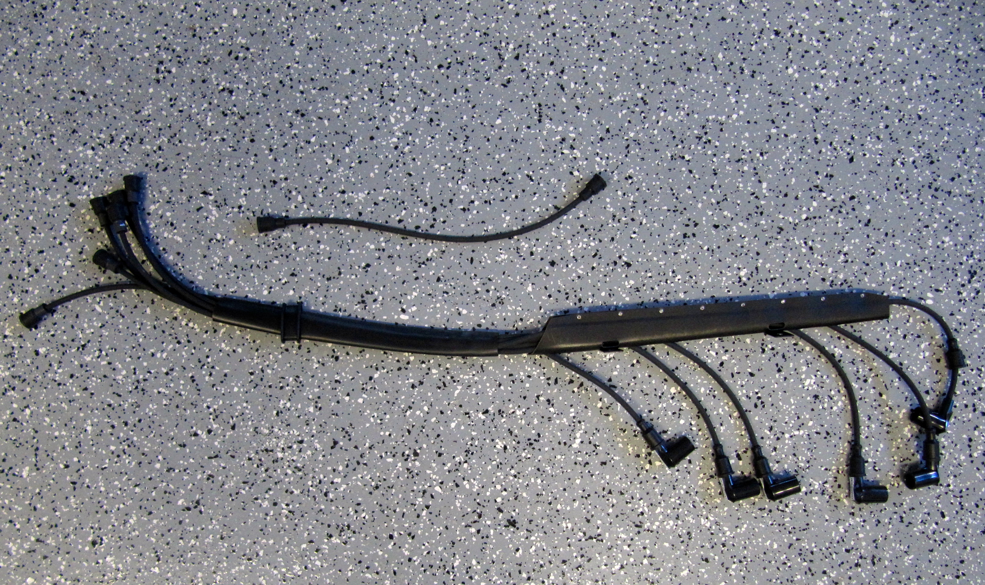
This is an image of the contents of the kit:

W02F MES Central Door Locking Kit with Keyless Entry
This image illustrates the dimensions of one of the actuators:
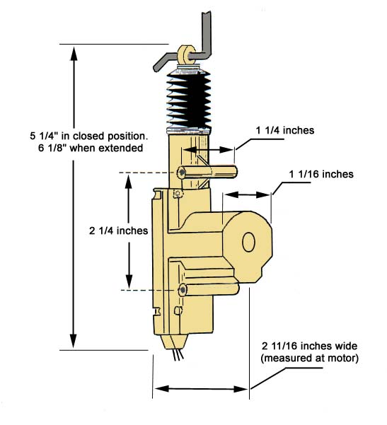
Actuator Dimensions
These are the installation instructions provided with the kit:W01F & W02F MES Central Door Locking Kit Installation Instructions
Mounting the Actuators to the Rear Doors
I began the installation of the four lock actuators with the RH rear door. Because the door window and lock hardware were not mounted to the door, I first installed these components. I did so to be sure that the actuator did not conflict with the operation of the window. Information on the installation of the window and lock components is provided in the “Door Handles and Locks” website entry https://valvechatter.com/?p=6027 and the “Doors and Windows” website entry https://valvechatter.com/?p=5485
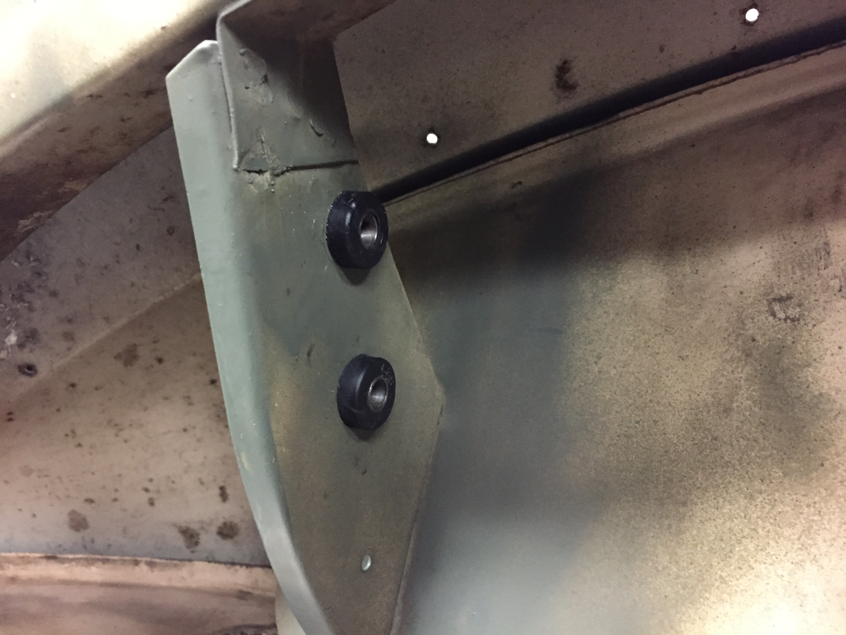
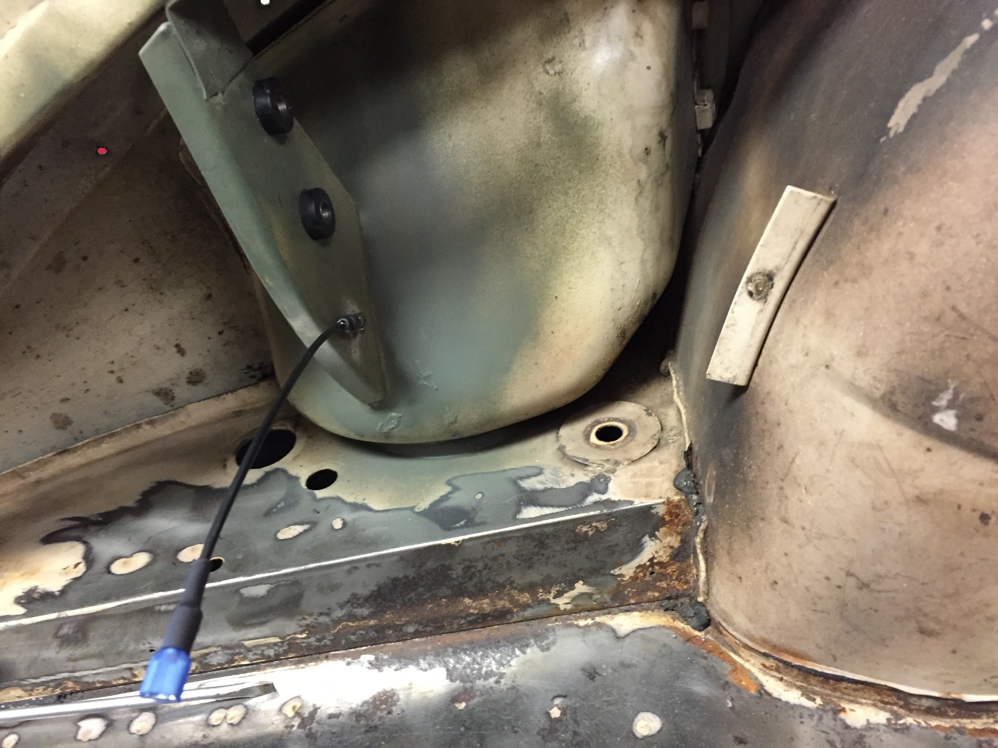
The kit incorporates mounting hardware including a yellow zinc bendable strap and the necessary screws. These images show the location of the rear door actuators (both doors are the same).
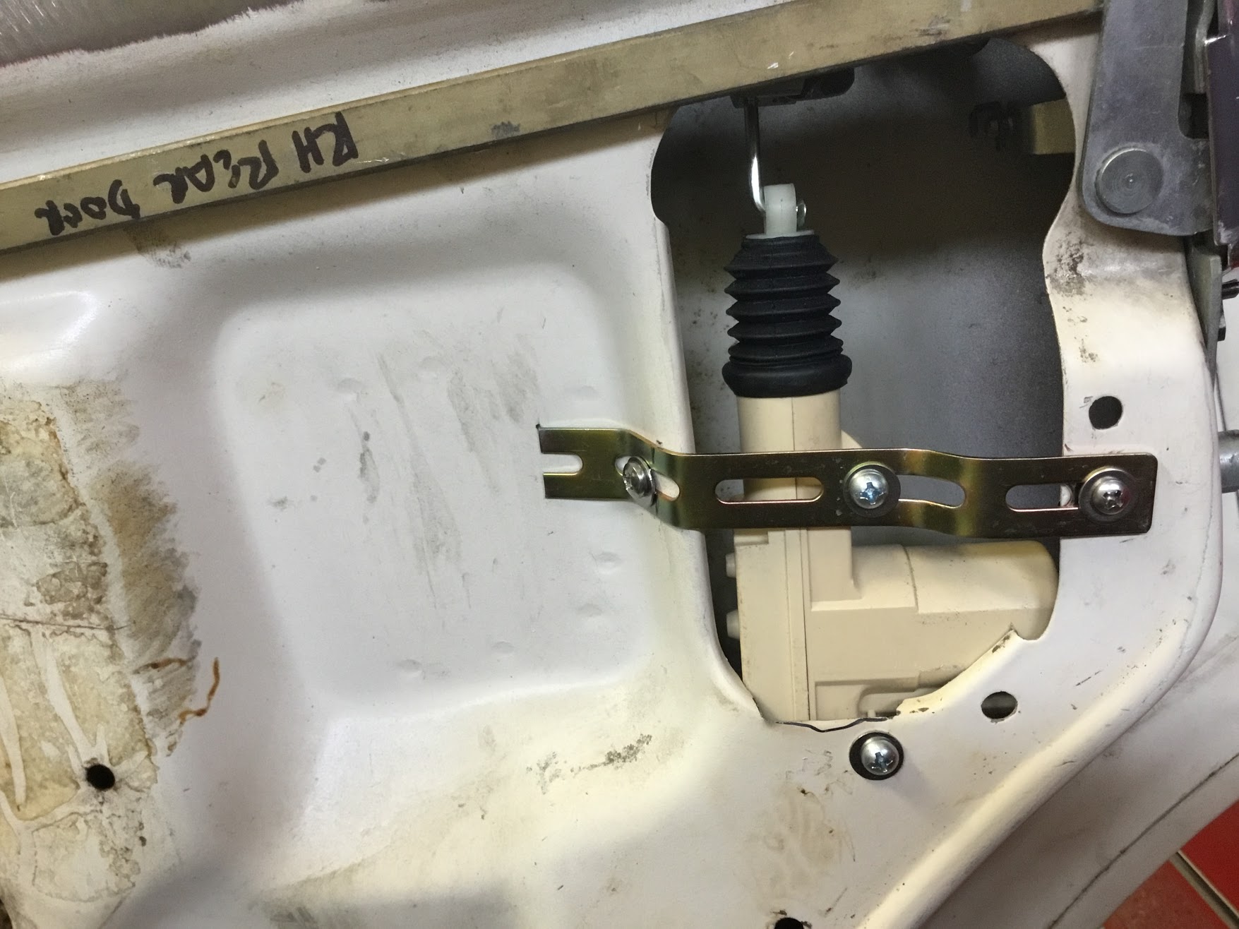
Lock Actuator RH Rear Door

Lock Actuator RH Rear Door
It was necessary to drill three holes in the door: two for the strap and one for the actuator body.
Connecting the Actuators to the Rear Door Locks
Connecting the actuator to the door lock is not difficult, but it is a little complicated to explain. The schematic diagram provided in the Service Manual on page 450 N.24 is helpful.
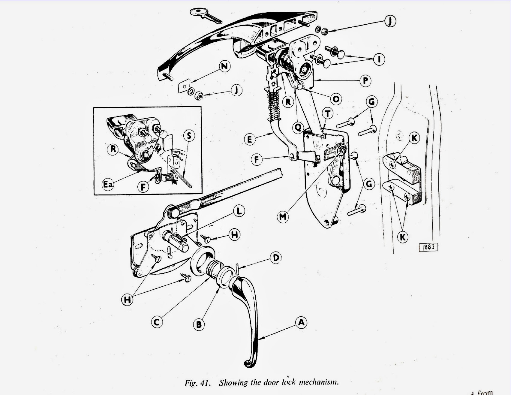
Jag MK2 Door Lock Mechanism Schematic
While most of the mechanism for the front and rear door are the same, there are some distinctions. The rear door components are shown in the small enclosed box in the diagram above. The connecting link (E) with a spring in the diagram is for the front door and the connecting link (Ea), without a spring, shown in the box and in the image below is for the rear doors.
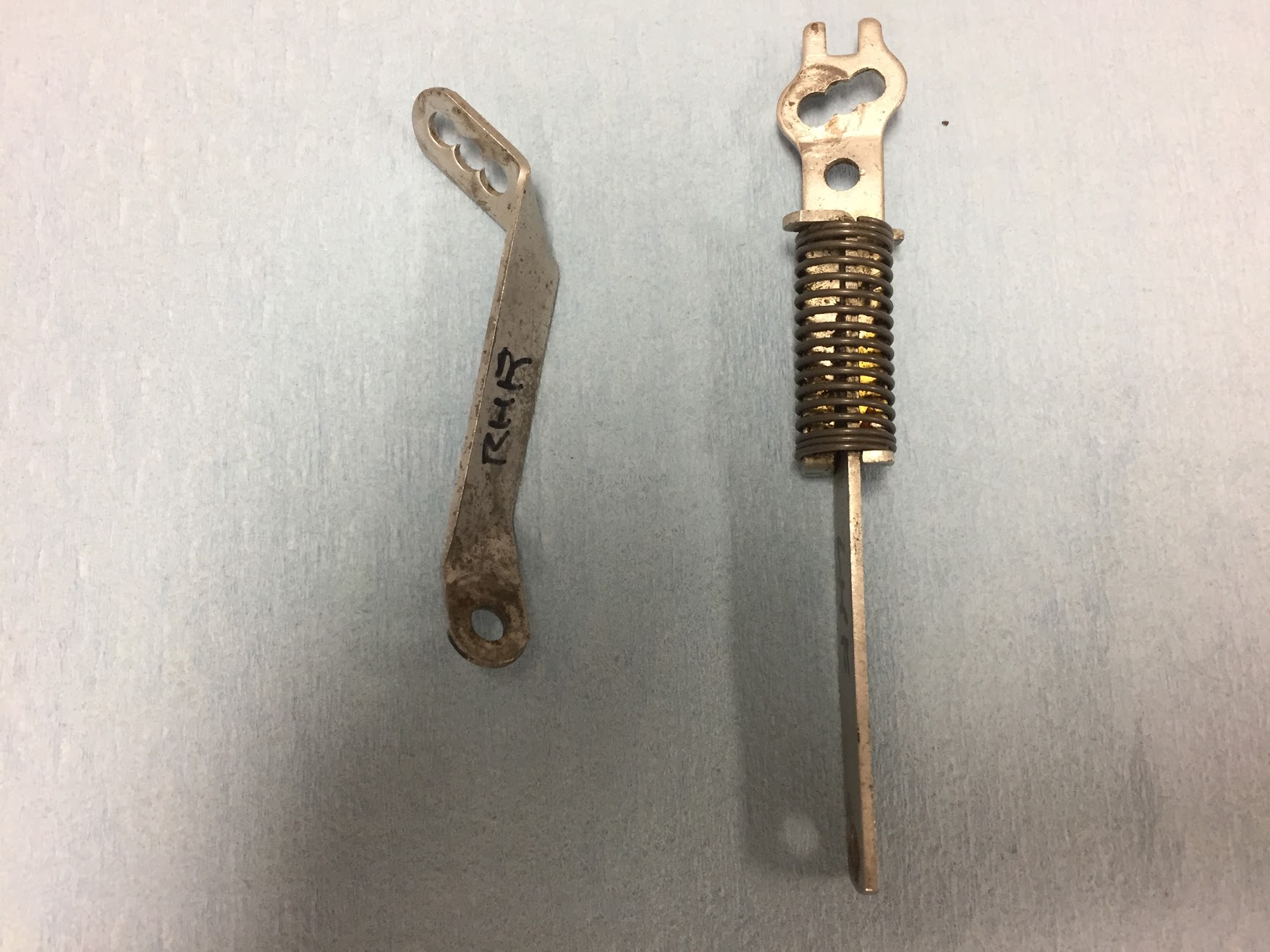
Lock Connecting Links Front and Rear
These connecting links do what their name implies: they connect the door handle locking mechanism and the remote control to the door lock and striker plate.I use the connecting links for both front and rear doors to connect the actuator rod, supplied in the kit, to the car’s locking mechanism. This is accomplished through the use of a small rod clamp that is provided in the kit.

Actuator Rod Clamp
The clamp has two set screws – one to attach the block to the connecting link (The factory lock rod in the diagram) and the other to connect to the actuator’s rod.
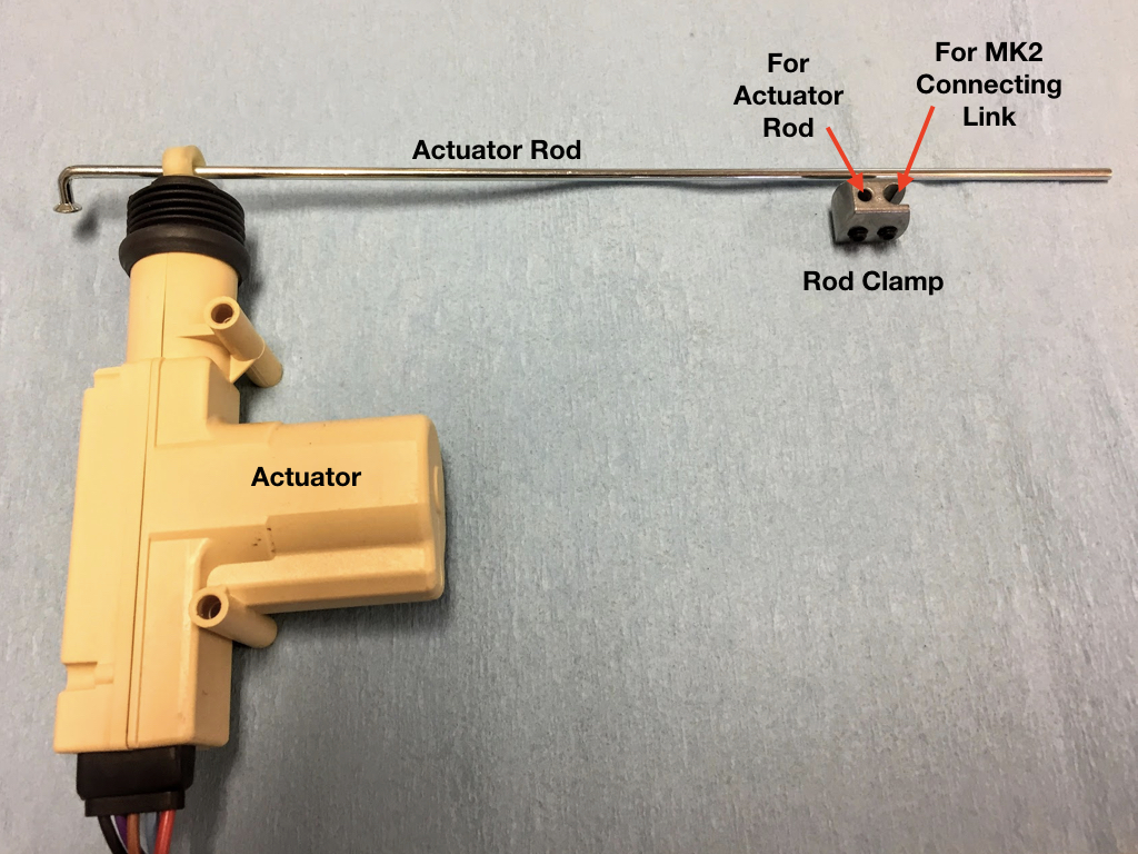
Actuator, Actuator rod and Rod Clamp
For the rear doors, to facilitate connection of the components without interference with the window frame, I chose to disconnect the connector link at the dowel (F) shown in the diagram at the top of the page. This will mean that the rear doors will not be locked and unlocked using the door handles which is of no matter to me since the actuators will be doing the job.
I then straighten the connecting link (removed the bends) and used it for the new connection to the connector block. To make the connection, the Actuator Rod needed to be bent slightly.
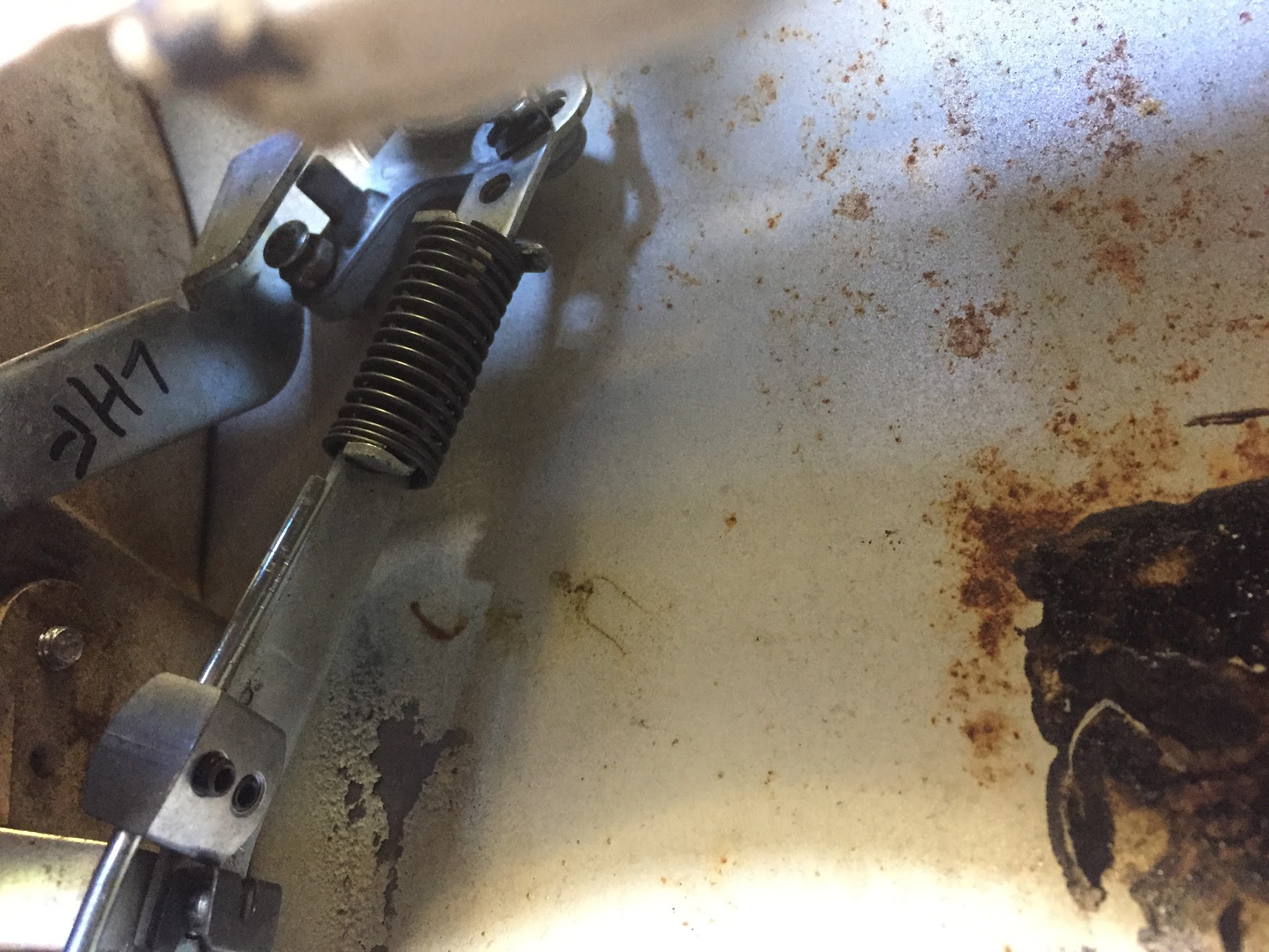
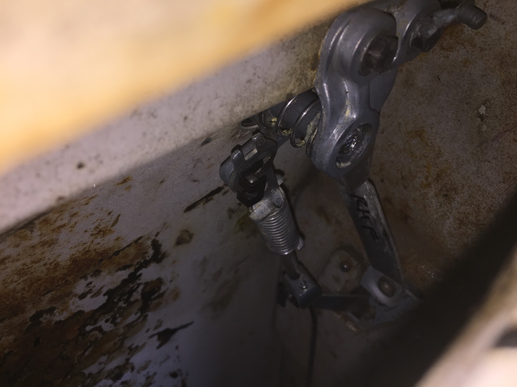
After installing the actuators in both rear doors, I tested them with a power source and was satisfied that they both operated effectively. The photos below show where the rod clamp attaches to the rod and to the connecting link. The position will be important when final assembly occurs.
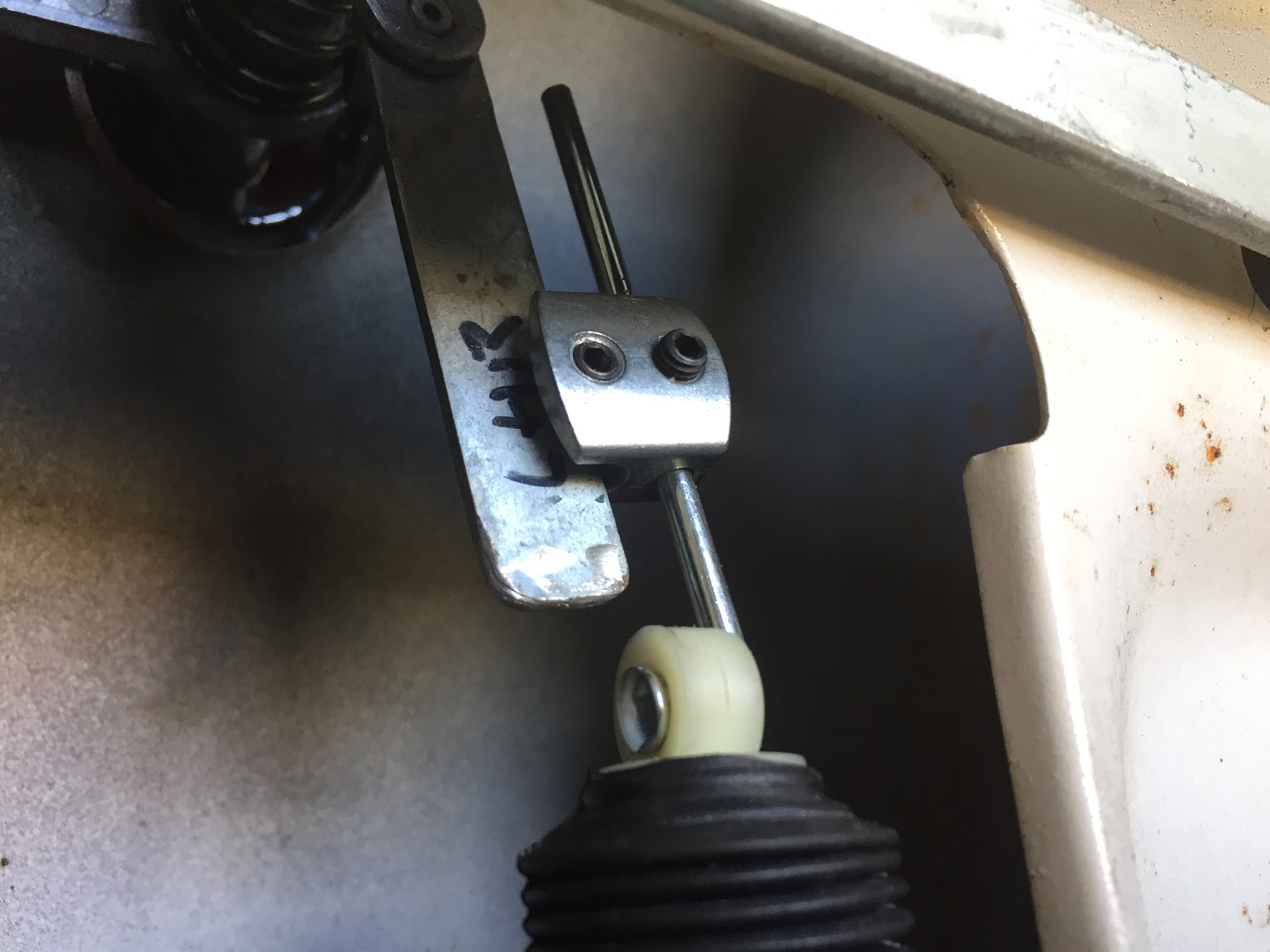
LH Rear Door Lock Connecting Link
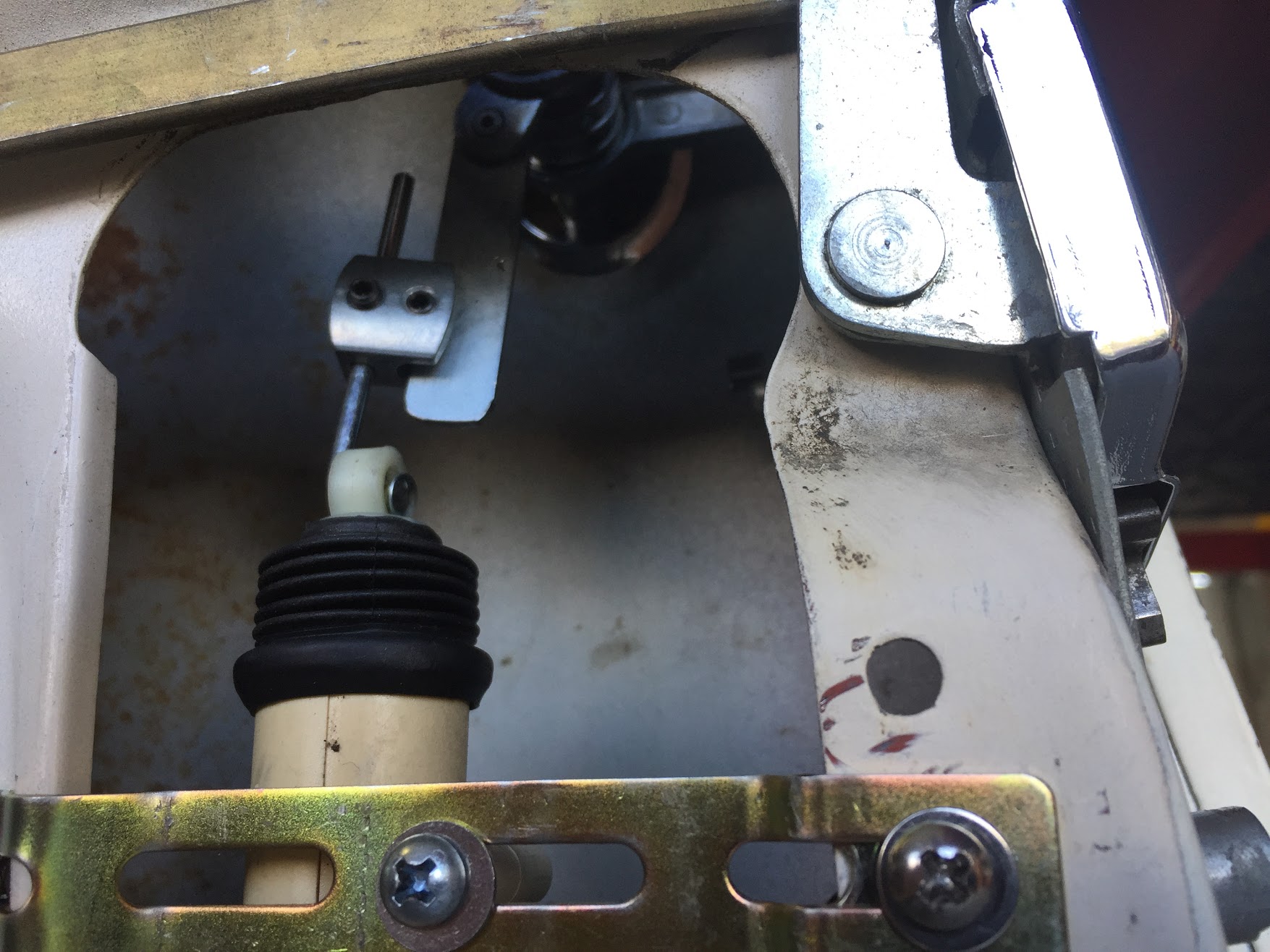
RH Rear Door Lock Connecting Link Position
Mounting the Actuators to the Front Doors
Because the door window and lock hardware were not mounted to the door, I first installed these components. I did so to be sure that the actuator did not conflict with the operation of the window. Information on the installation of the window and lock components is provided in the “Door Handles and Locks” website entry https://valvechatter.com/?p=6027 and the “Doors and Windows” website entry https://valvechatter.com/?p=5485
The front doors are a bit more of a challenge when contrasted with the rear doors.
To keep the actuator in a vertical position, I decided to open a hole in the door interior face. The hole can be seen in the following image:
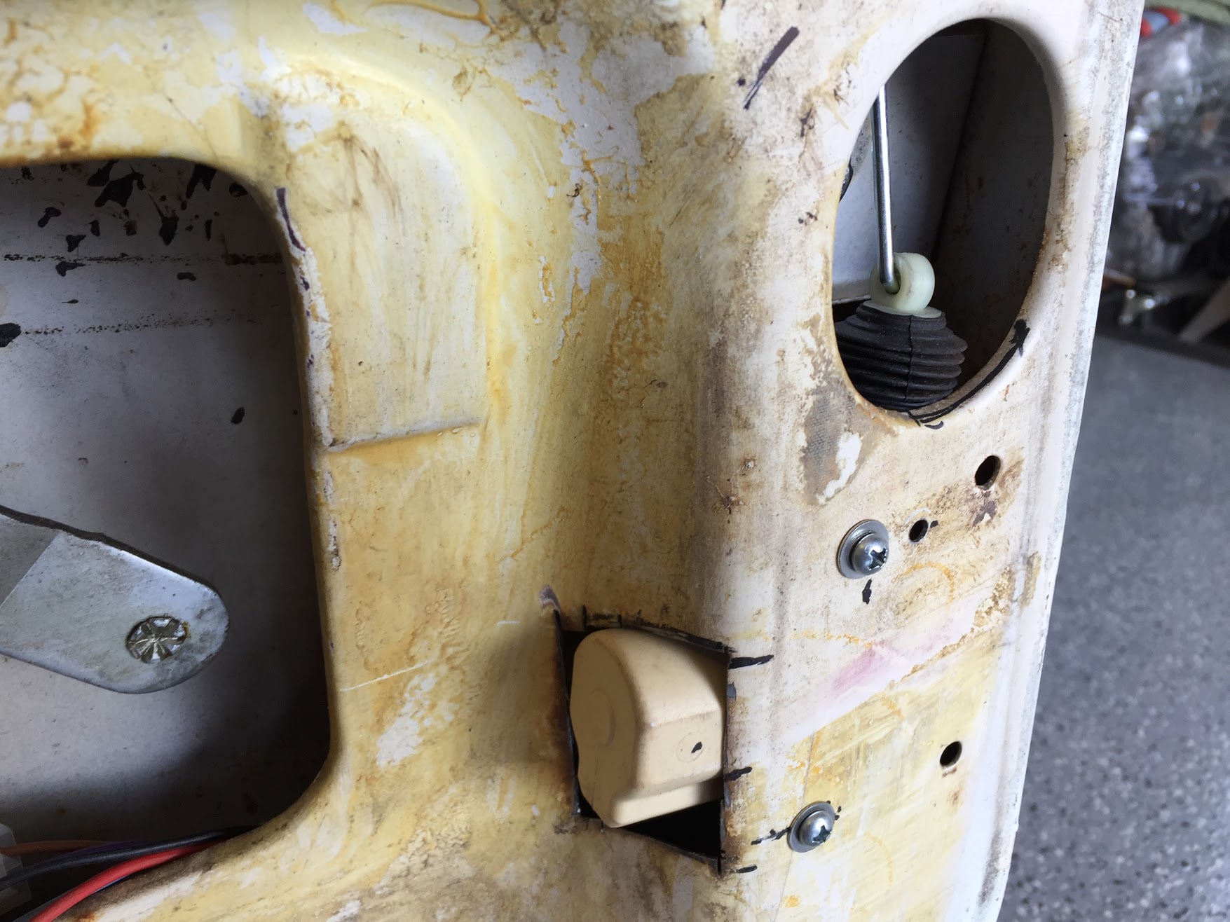
RH Front Door Modification for Actuator
As with the rear door actuators, the front actuators are mounted to the door with two, kit provided, 1″ self tapping screws.
Connecting the Actuators to the Front Door Locks
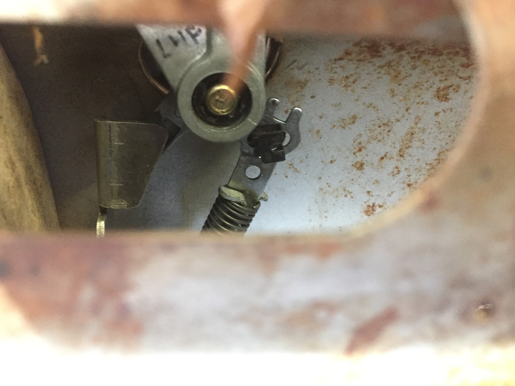
Unlike the rear doors, I want to use the interior door handle to activate the lock/unlock mechanical mechanism so I kept the original connecting link secured to the lever on the dowel on the door lock (F) in the schematic above. As suggested in the Service Manual I mounted the connecting link in the center position. But, after some experimentation. I found that the most forward position of the three worked best in my case. The photos below show where the rod clamp attaches to the rod and to the connecting link. The position will be important when final assembly occurs.
The kit directions make the following point: The alignment of the front door actuators (5 wire) on the MES lock kit is very important to proper operation. If the actuators are not properly aligned and centered it will cause the system to rapidly lock and unlock the doors or not allow you to lock or unlock the doors.
LH Front Door Lock Connecting Link
LH Front Door Lock Connecting Link Mounting Position
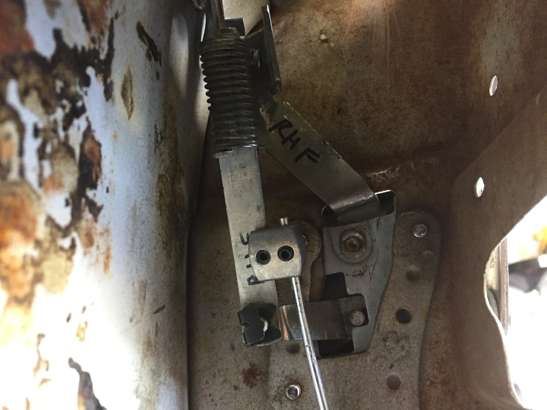
RH Front Connecting Link Mounting Position
RH Front Door Lock Connecting Link Forward Mounting Position
It is necessary to drill holes in the “A” pillar, the rear face of the “B/C” pillar and in the face of each of the doors to facilitate the travel of the electrical wiring for the operation of the actuators. To protect the wiring and to yield a finished look, some type of wiring loom or boot is needed. I searched for some time trying to find a product that I liked. Hot Rodders often use a stainless loom such as the pair in the image below:
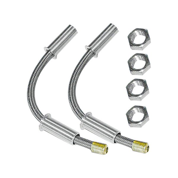
Stainless Door Wiring Loom
In reality, these are quite large and in my opinion just don’t look proper on the Jaguar. I was also concerned about these making a rubbing noise inside the doors when they were operated.
I never did find anything that was totally satisfying; however, I did locate some soft rubber looms that seems to offer the best option for me. They are very flexible and will compress and extend nicely. These came from Summit Racing but are produced by Electric-Life Power Windows and Accessories: https://www.electric-life.com/product/4301-70-011-58-diameter-flexible-inclined-rubber-tuber/ part number – 4301-70-011 5/8″ diameter Flexible Inclined Rubber Tube. To install it was necessary to drill a 3/4 hole in the pillar and the door at each location.

Rubber Door Loom

Rear Door Rubber Loom Installation

Front Door Rubber Loom Installation
Wiring
The electrical control circuit for the power locking system is comprised of two components. The first is the MES central locking system that will function properly without the addition of the wireless entry unit. In fact, the directions specify full installation and system testing of the MES central locking system alone. Only after the MES central locking system is functioning as it should, does one then add the keyless entry unit.
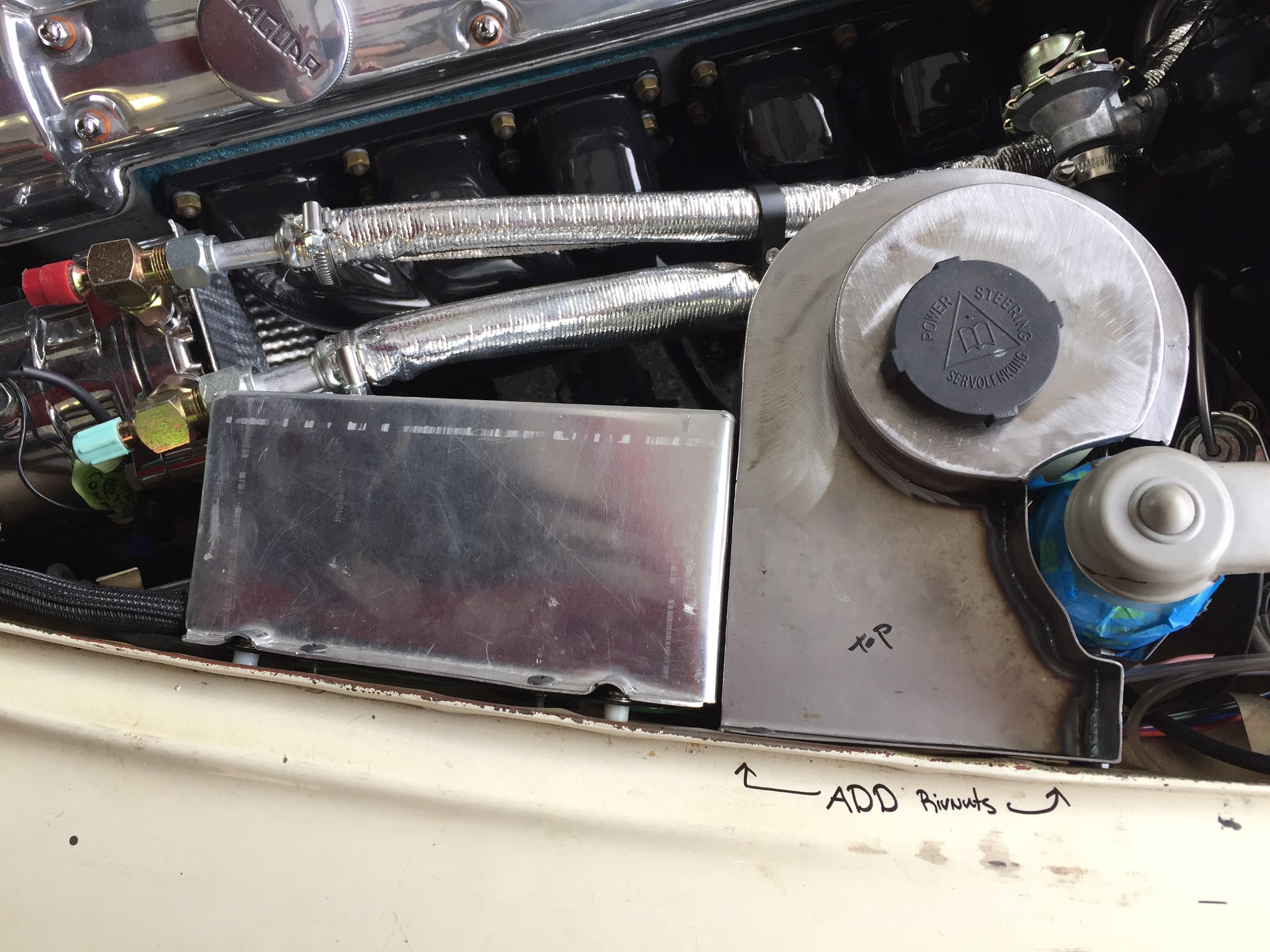
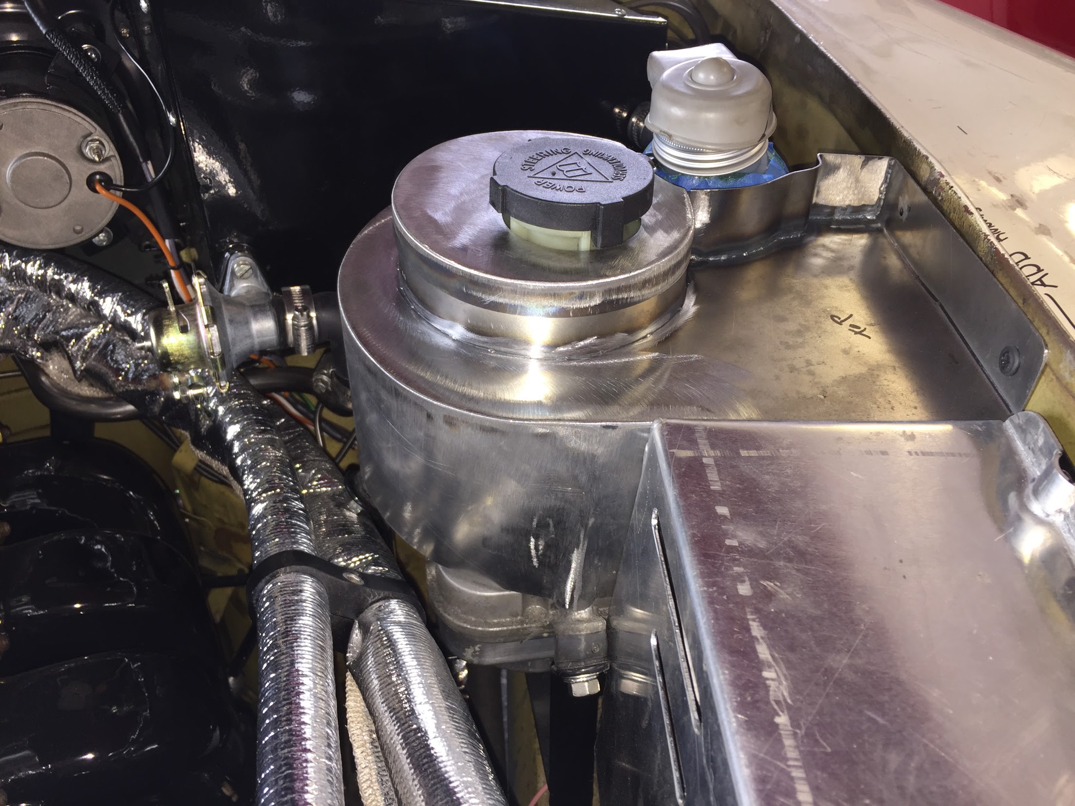
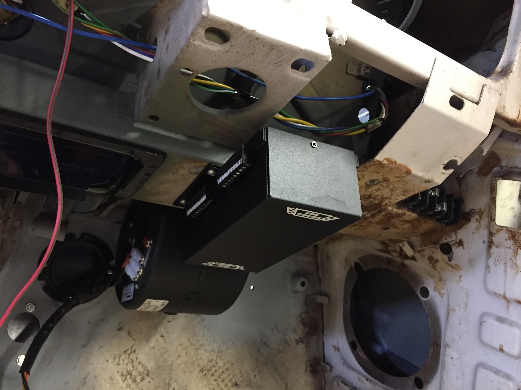
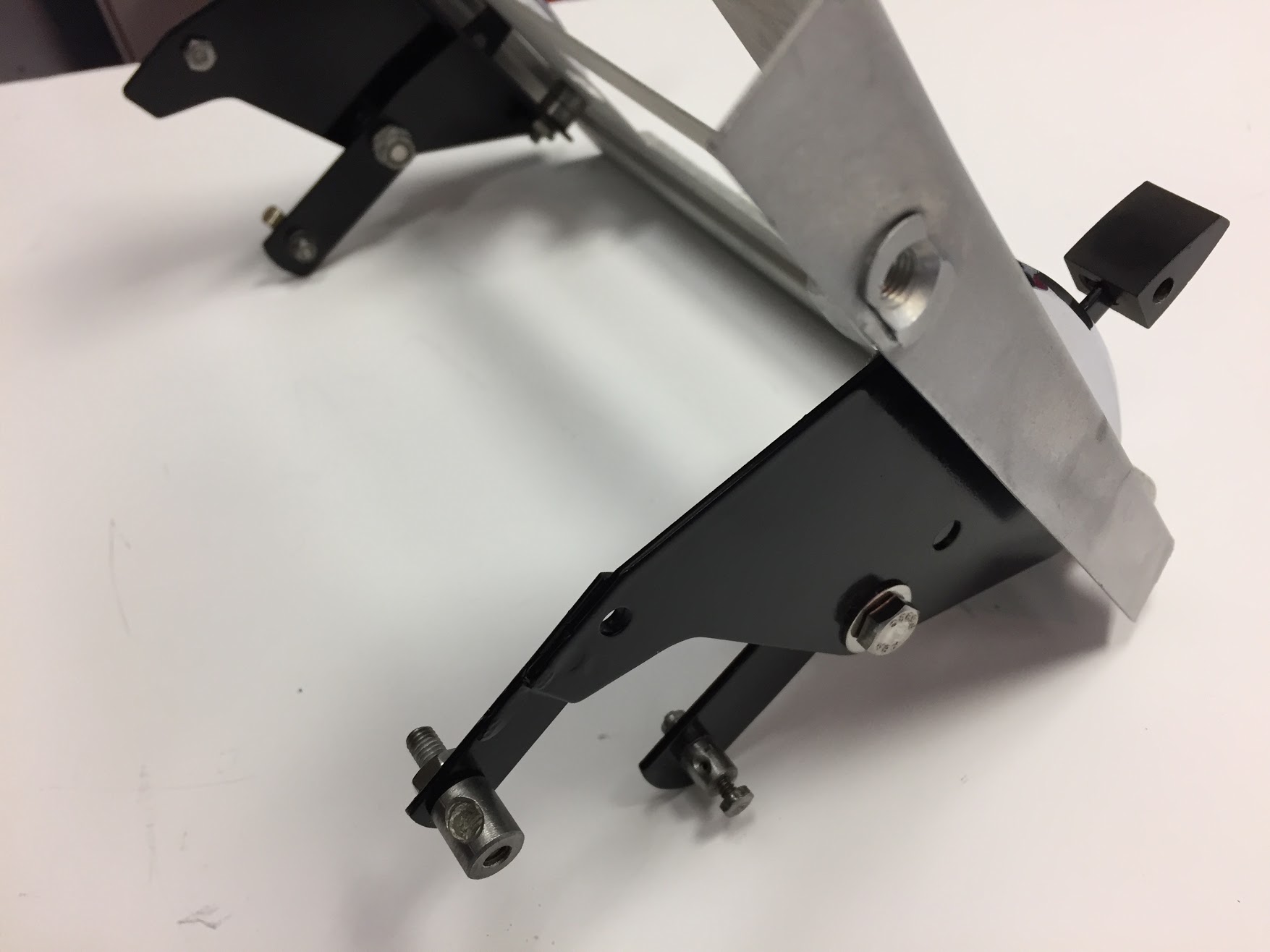
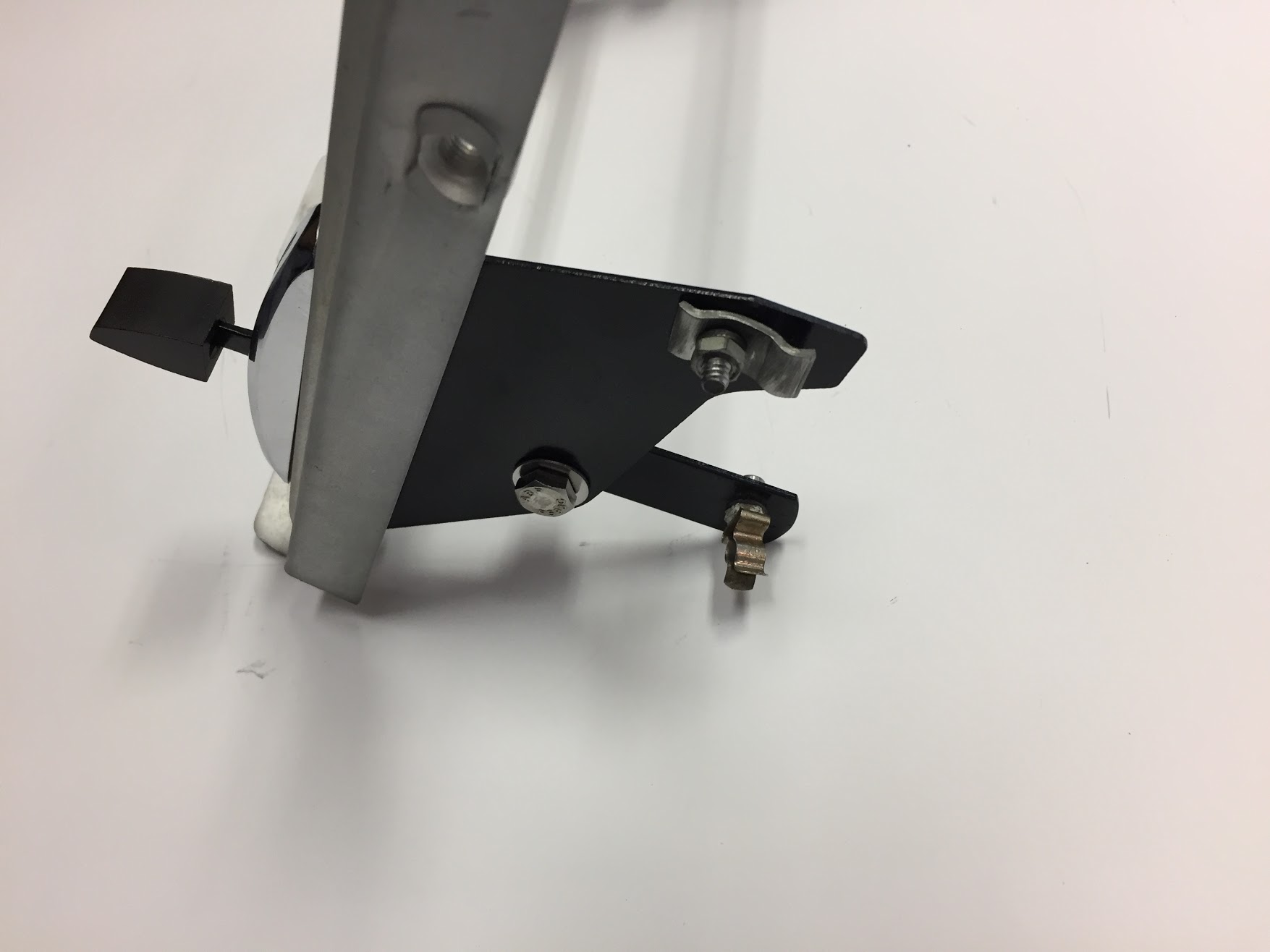
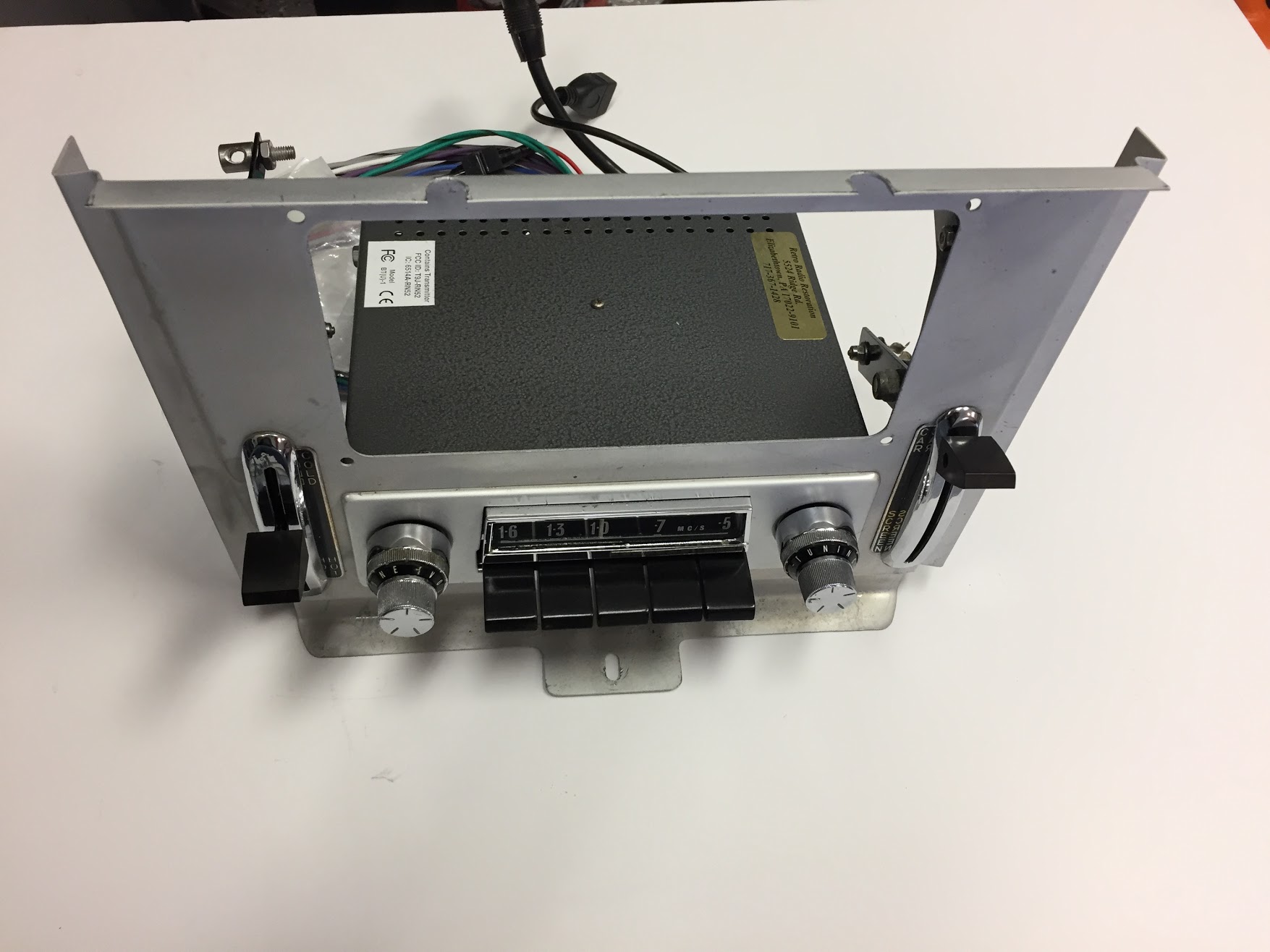
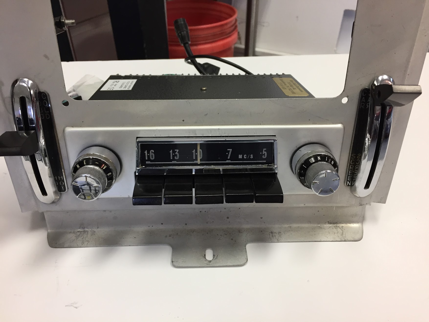
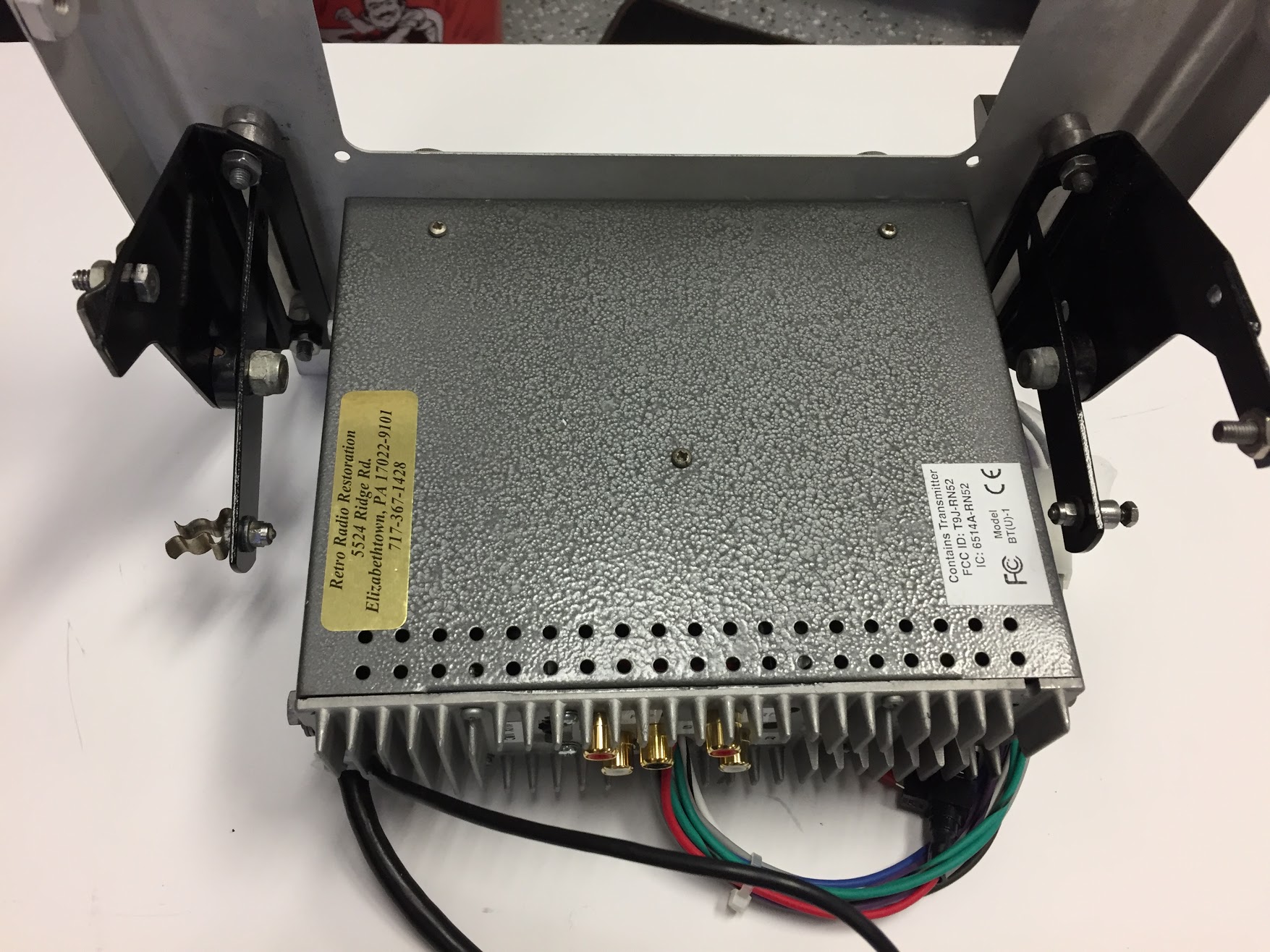
The MES control module is the turquoise blue box in the photo at the top of this post. A five way relay and a spade connector for ground wires is incorporated into the control module. I decided to mount the control module below the newspaper shelf and behind the radio. I installed several nutserts into the brace below the newspaper shelf to mount relays. The MES control module is secured with one #10-24 x 1/2″ machine screw and shake proof washer.
MES Control Module Mounting
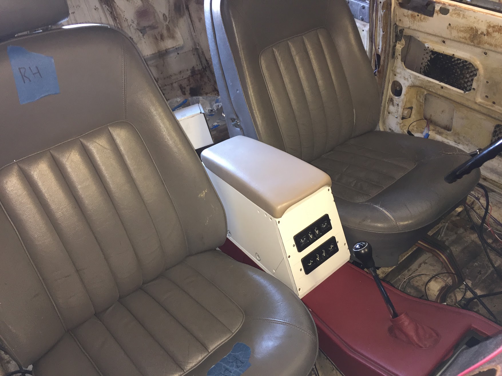
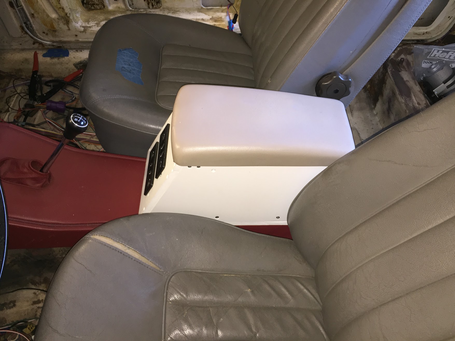
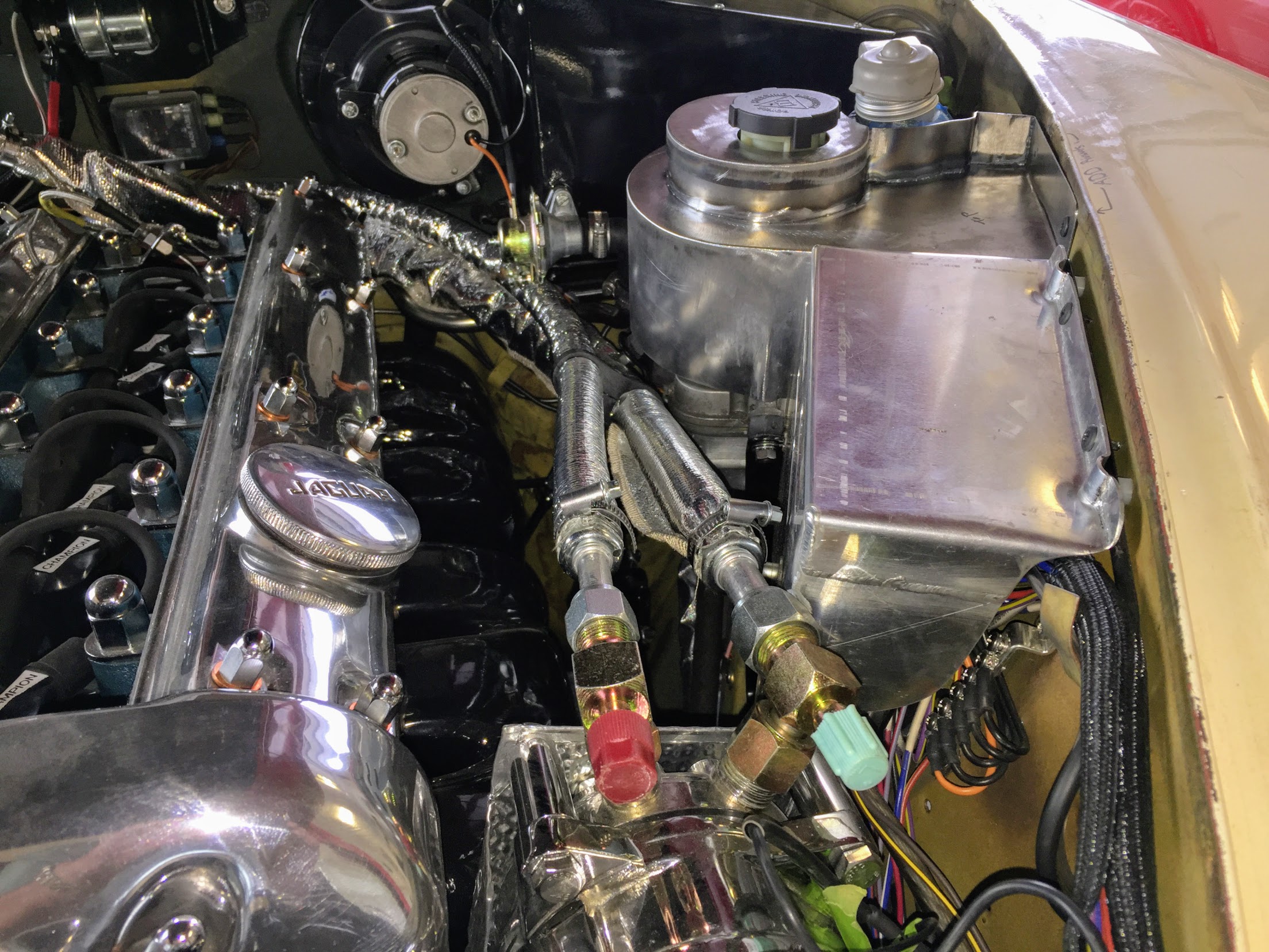
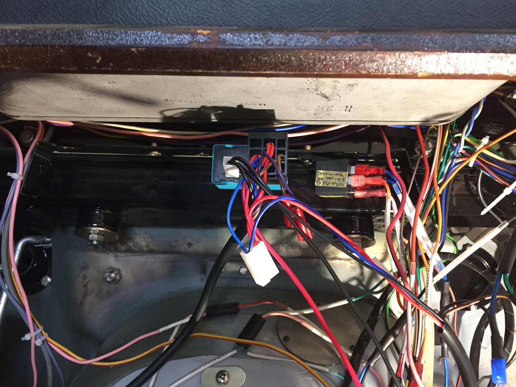
I chose to locate the AVITAL 2101/712T keyless entry module on the chassis brace behind and below the cubby box. This location is also directly above where I chose to locate the Classic Technologies Fuse Box. The AVITAL unit has four mounting tabs; however, it weighs next to nothing so I used only two of the mounts with two #10-24 x 1/2″ machine screws and shake proof washers.
I apologize for the wiring mess in the photo. I will clean all this up upon final installation.
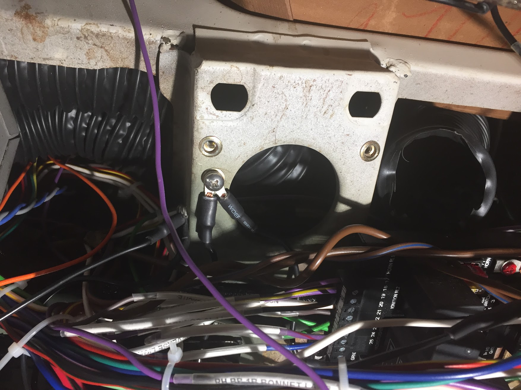
Nutserts installed to mount keyless entry module

AVITAL keyless entry module mounted
The actual wiring circuit for the central locking/keyless entry system may be found at the “New Wiring Harness Circuits” web site entry: https://valvechatter.com/?p=8114
The wiring for this project is fairly easy to install, however, because of the connections that must be made between the MES central locking system and the AVITAL keyless entry component, the schematic for the wiring does appear to be fairly complicated.
After installing the four door actuators and rod linkages, the two control modules, and all the wiring I energized the system and everything worked beautifully. I anticipate that this is one feature that I will enjoy. Having to lock and unlock the rear doors by reaching into the car and adjusting the handle could be a bit of a nuisance. Modern cars have spoiled us (me).