Chapter 9 – Disassembly

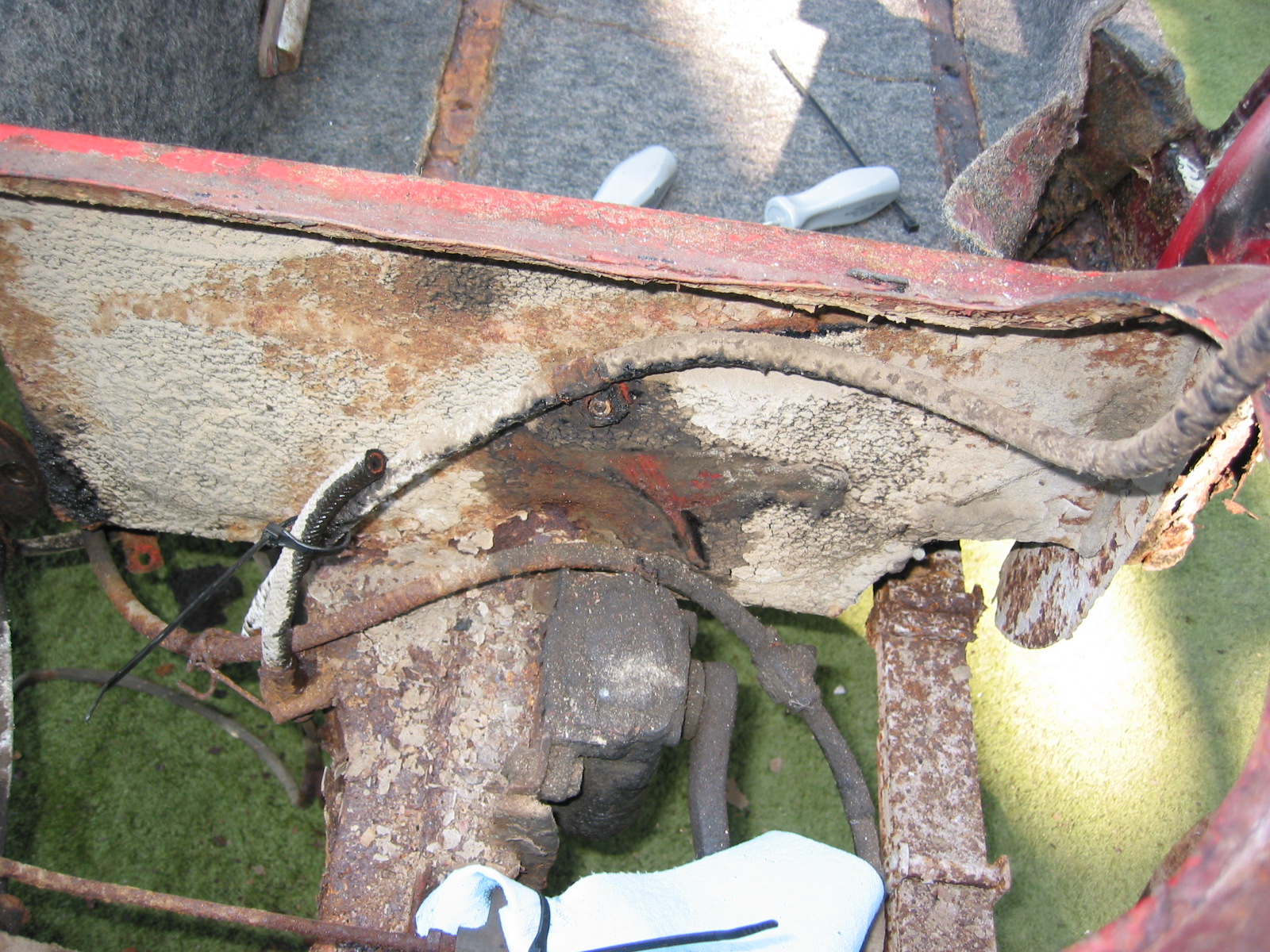
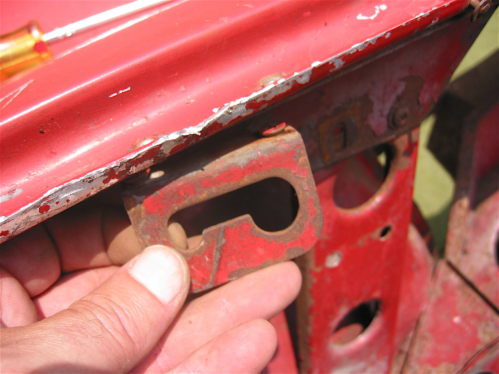
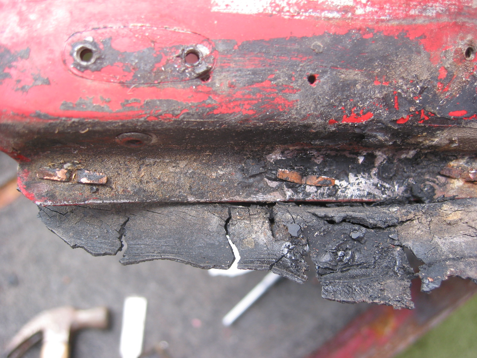
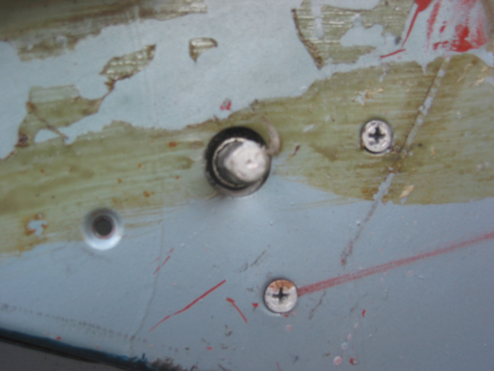
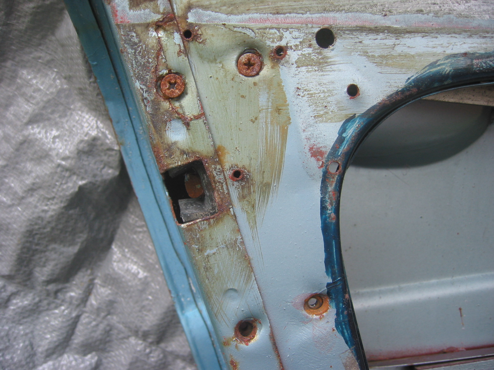
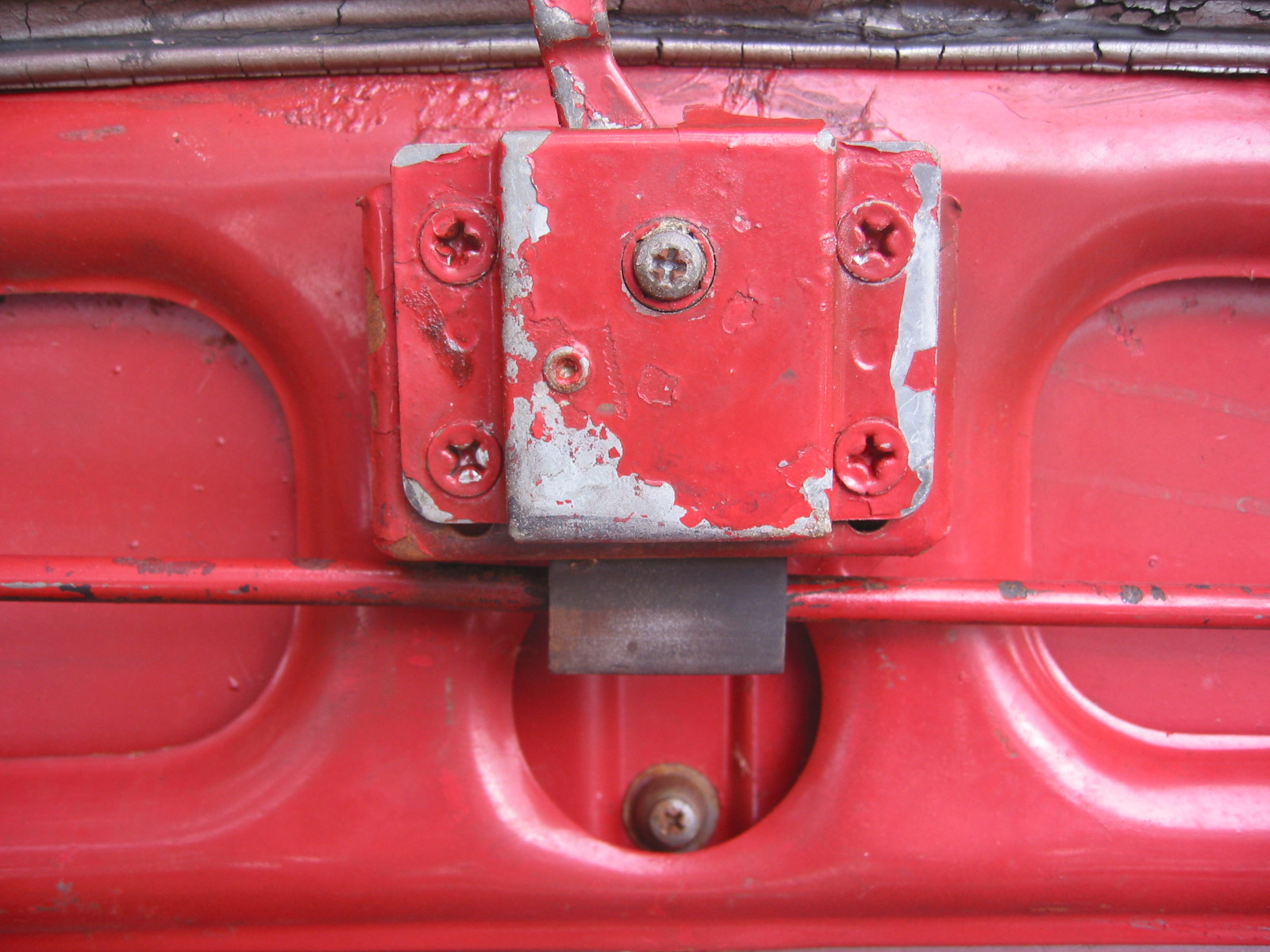
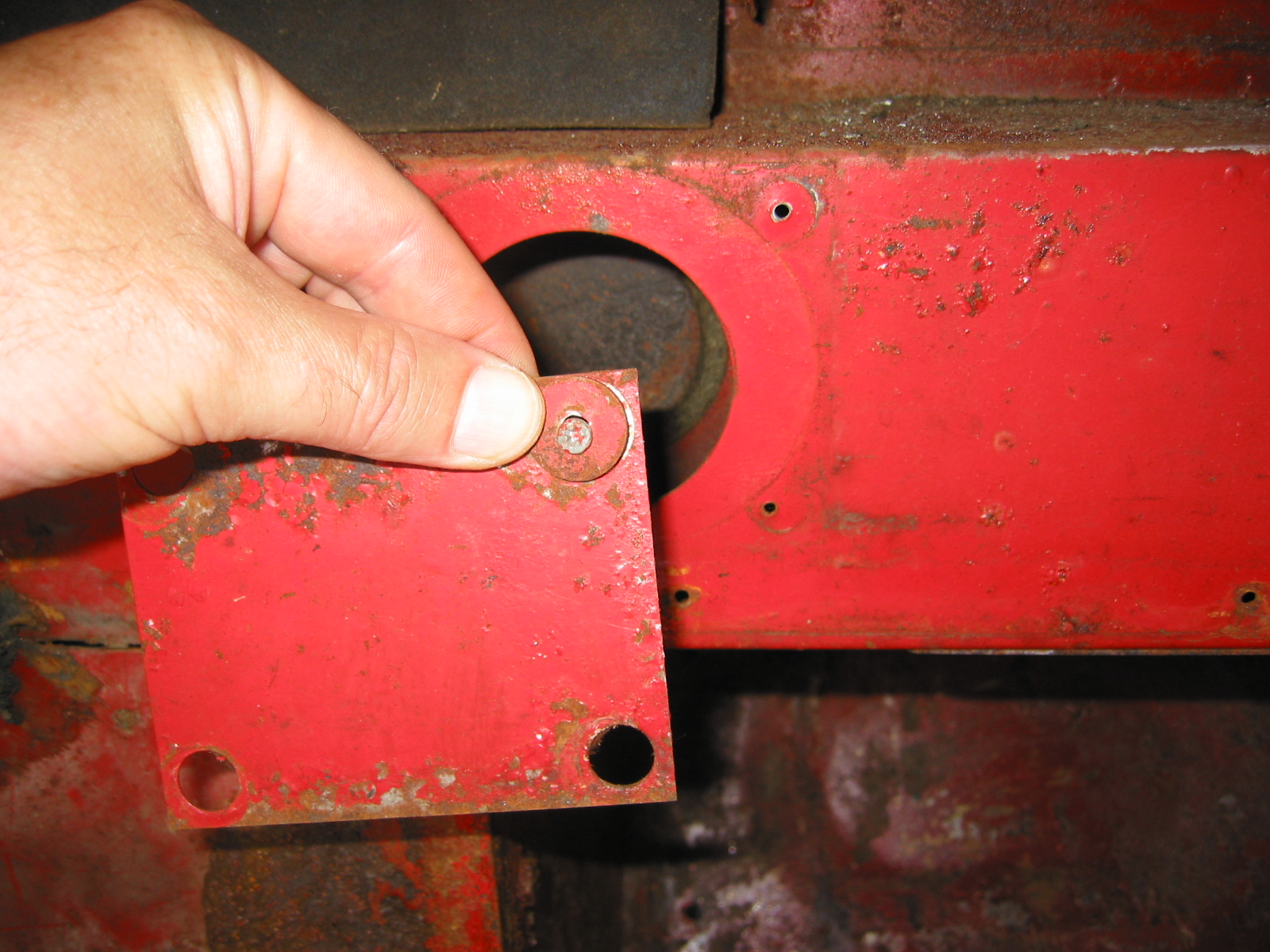
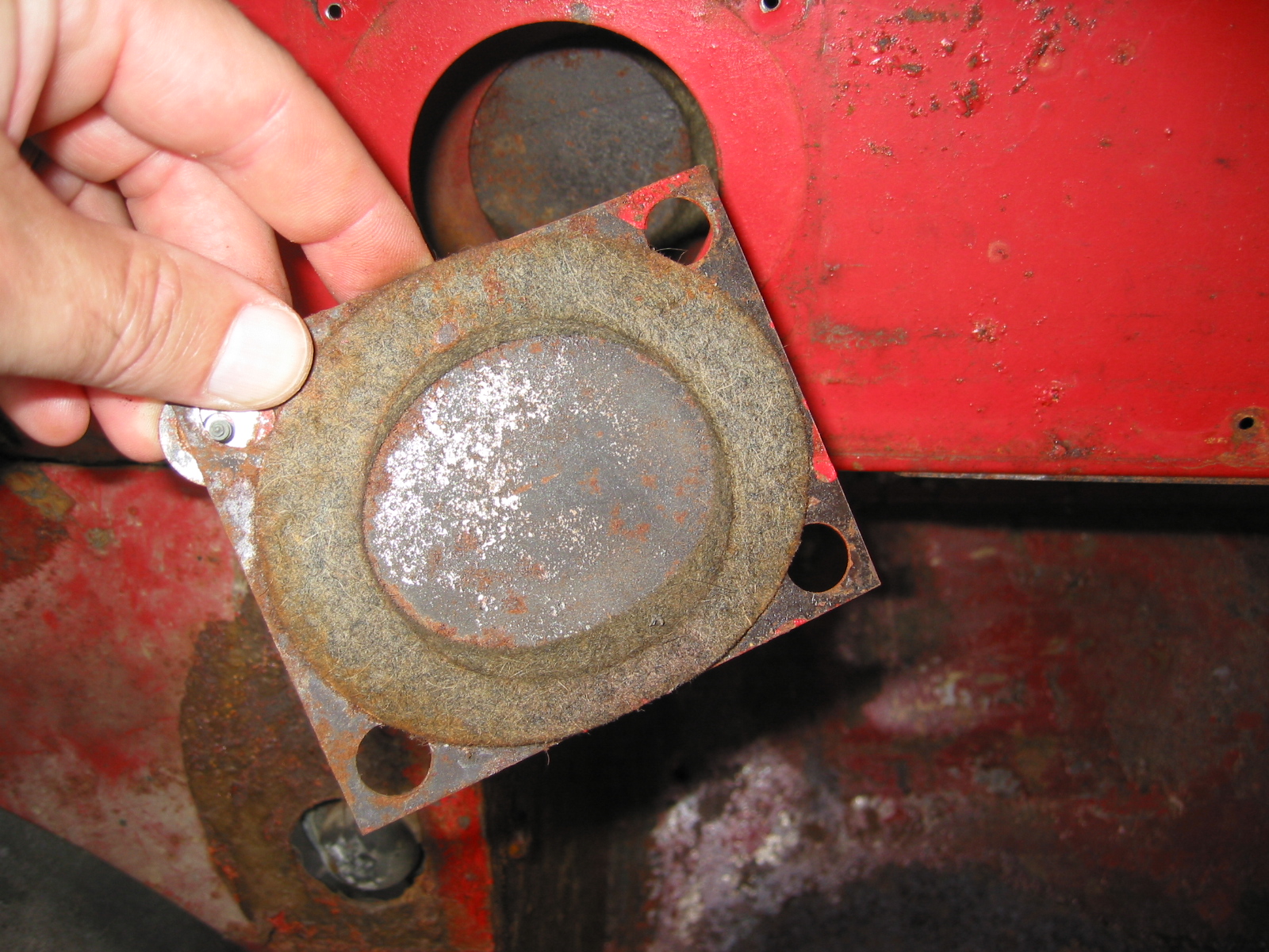
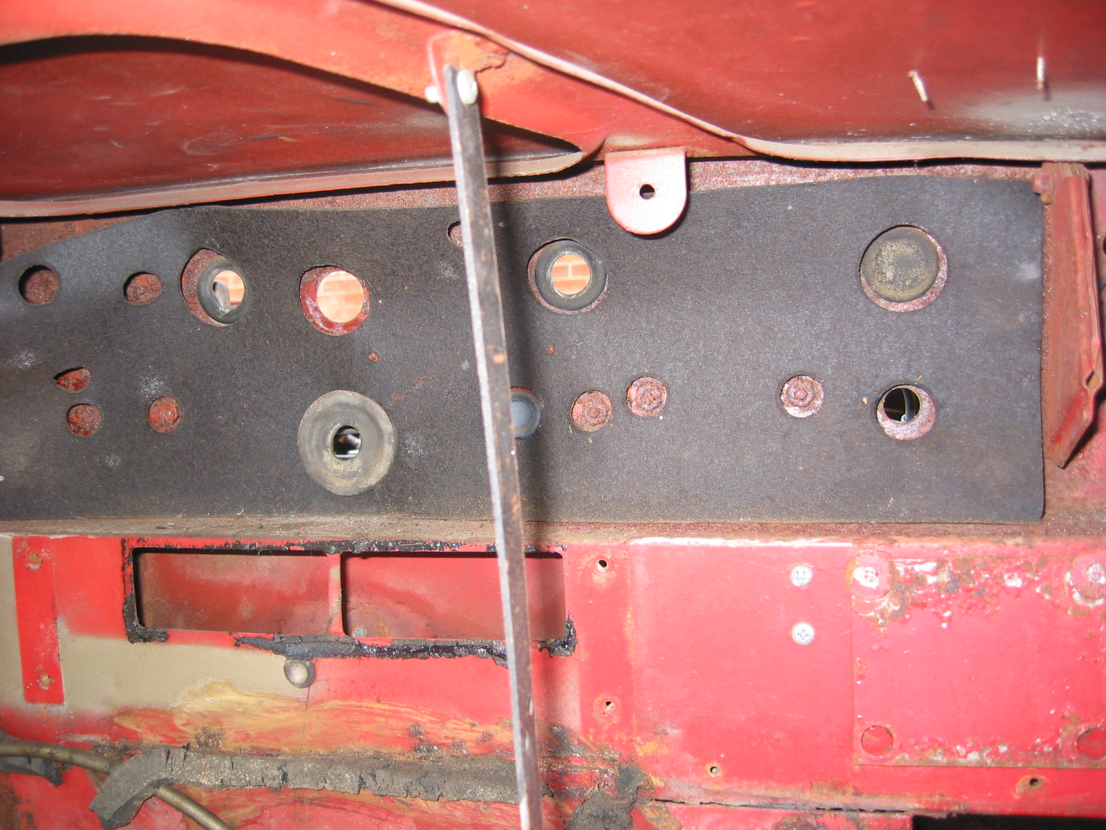
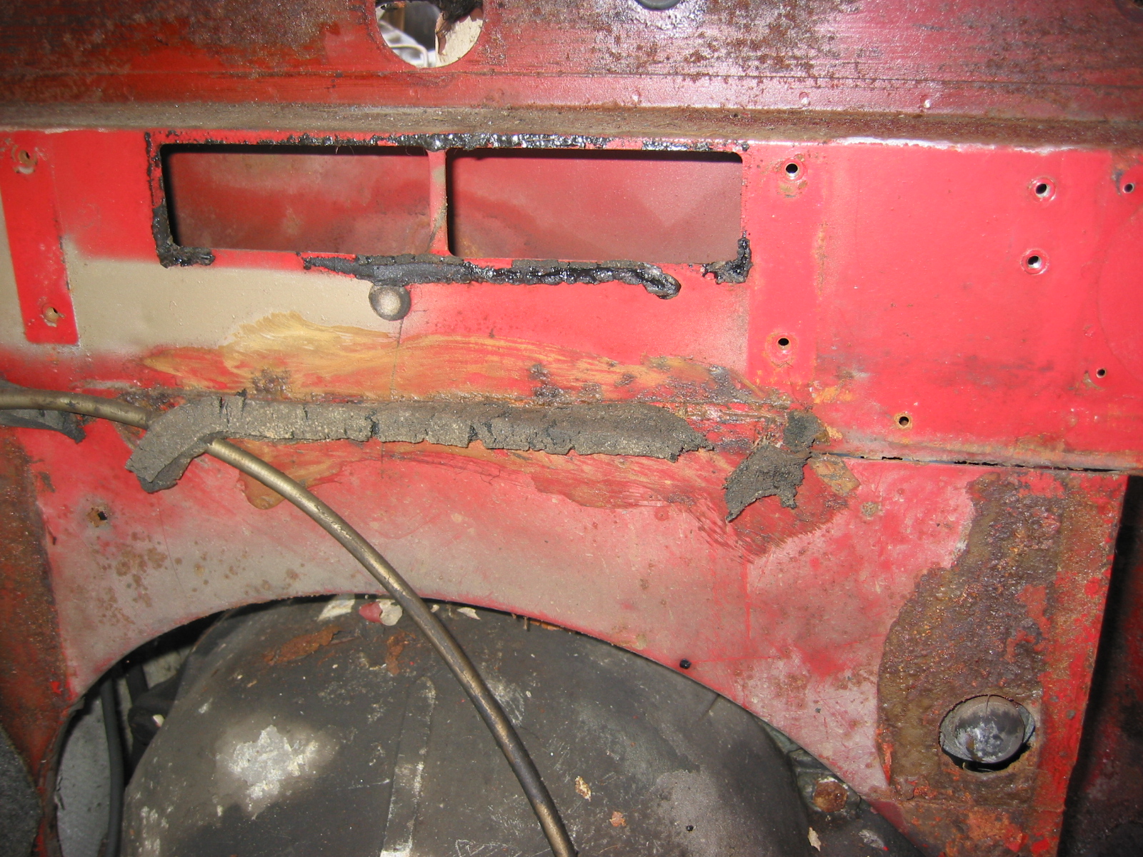
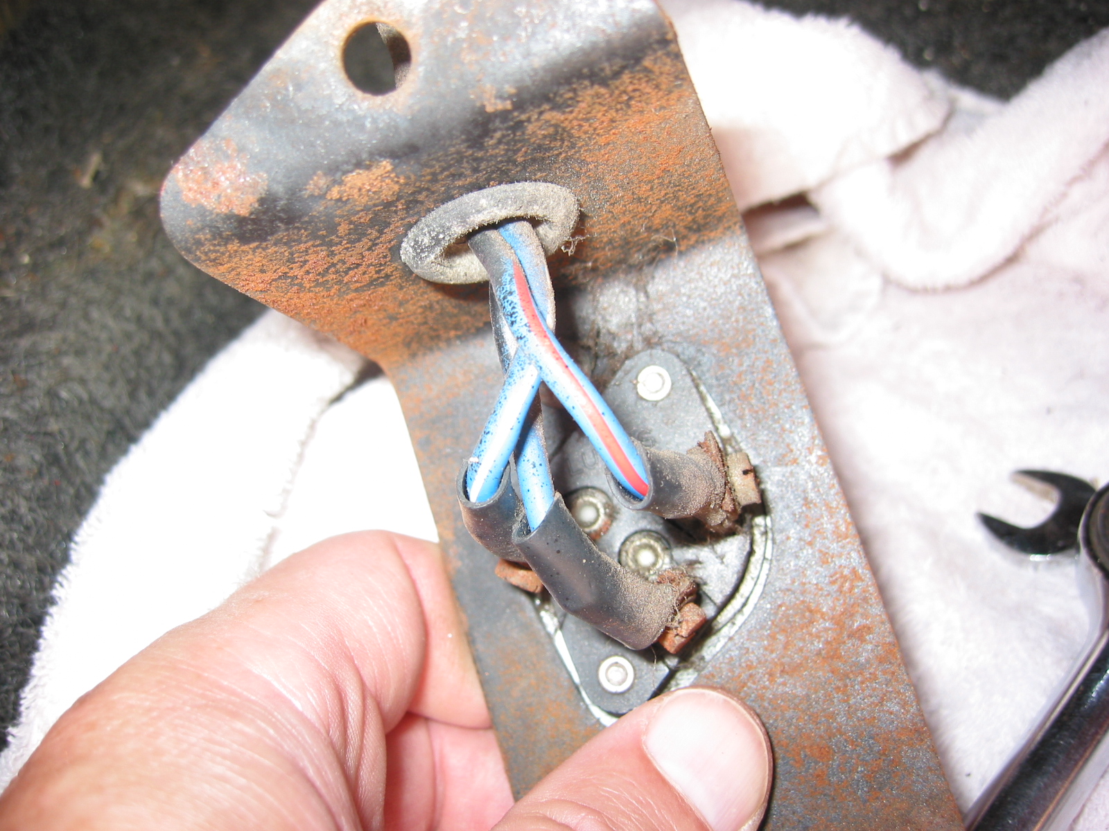
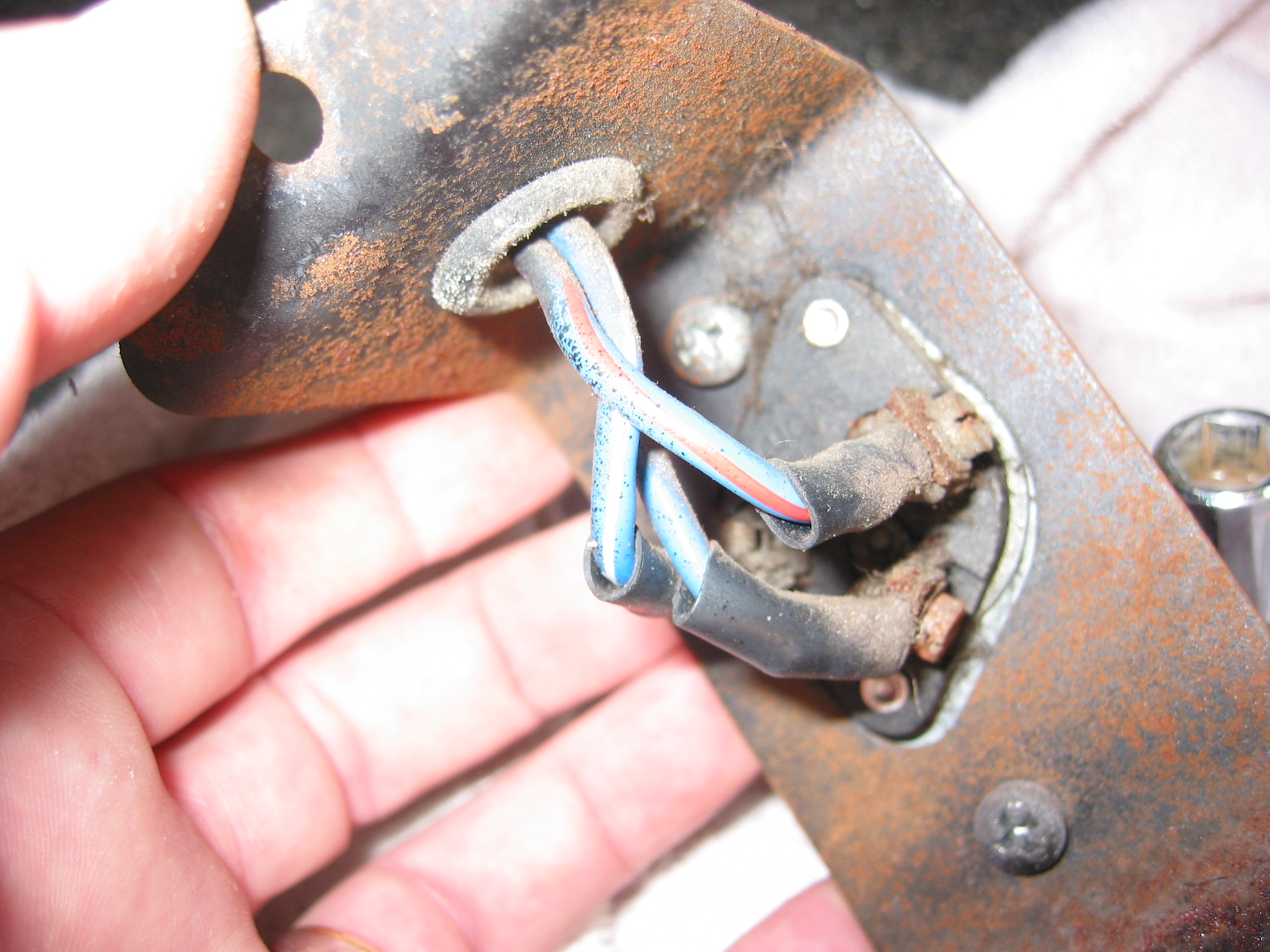
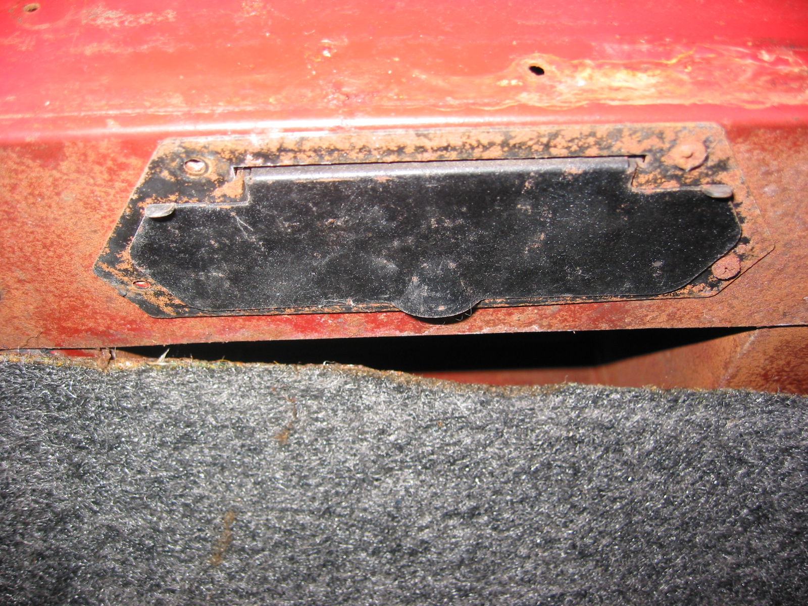
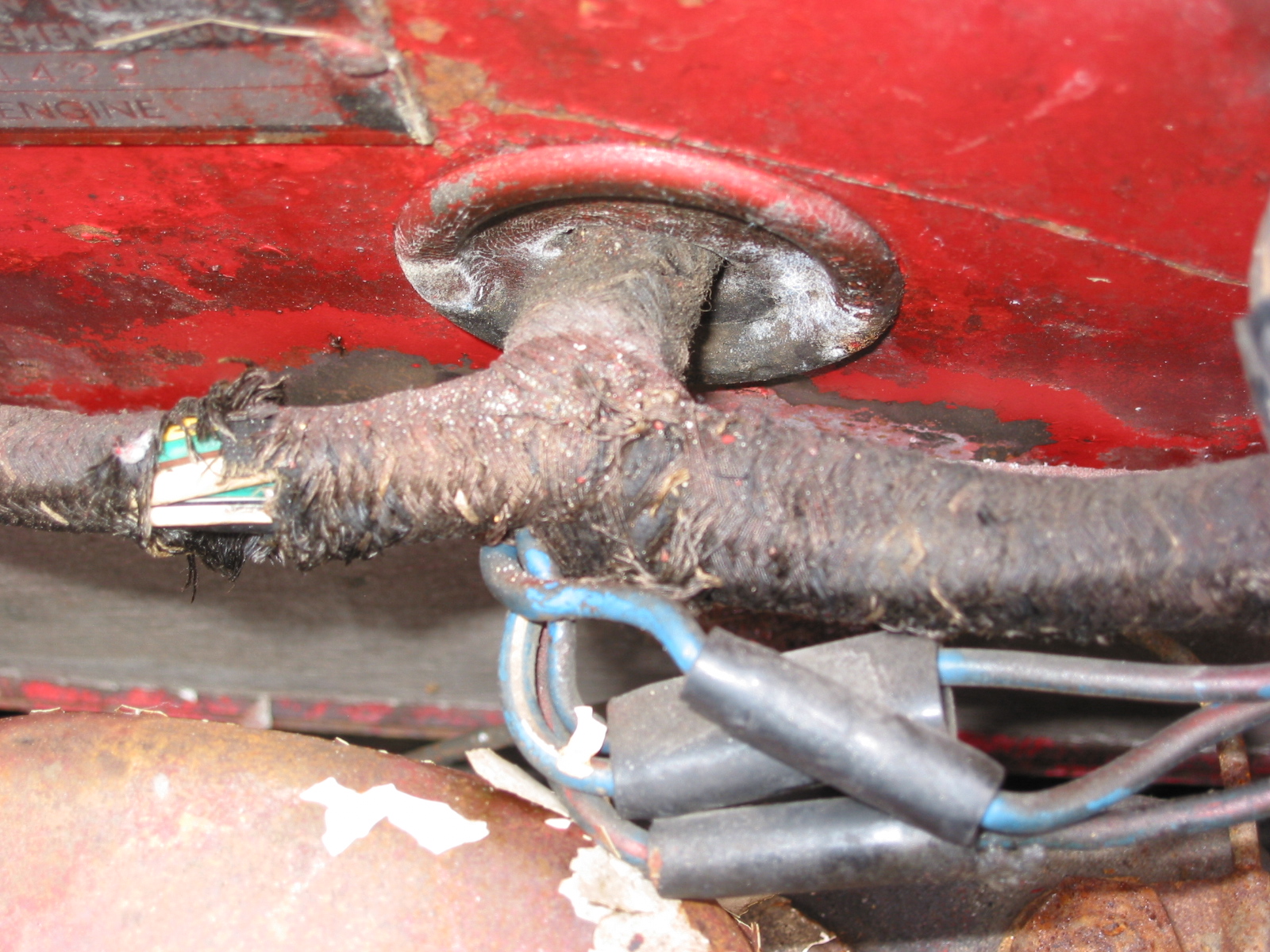
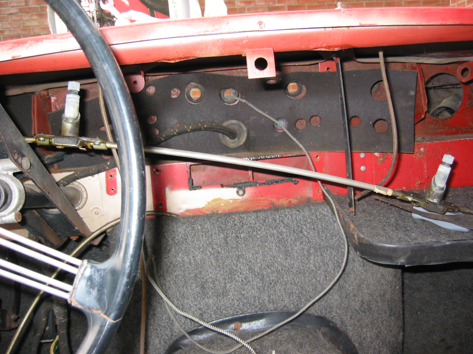
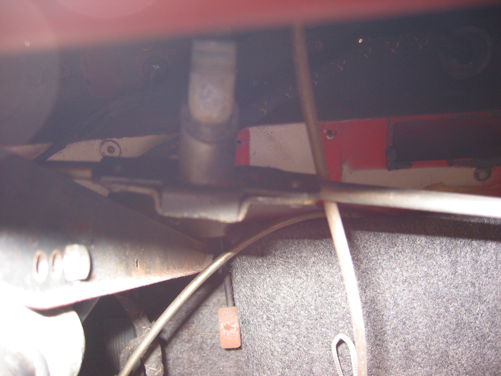
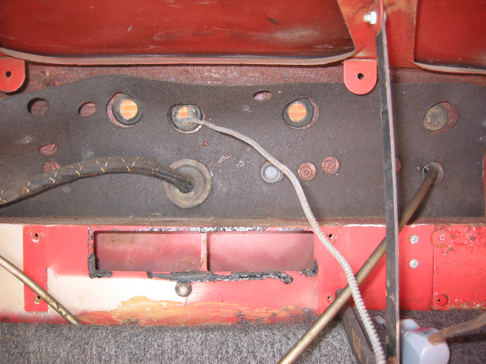
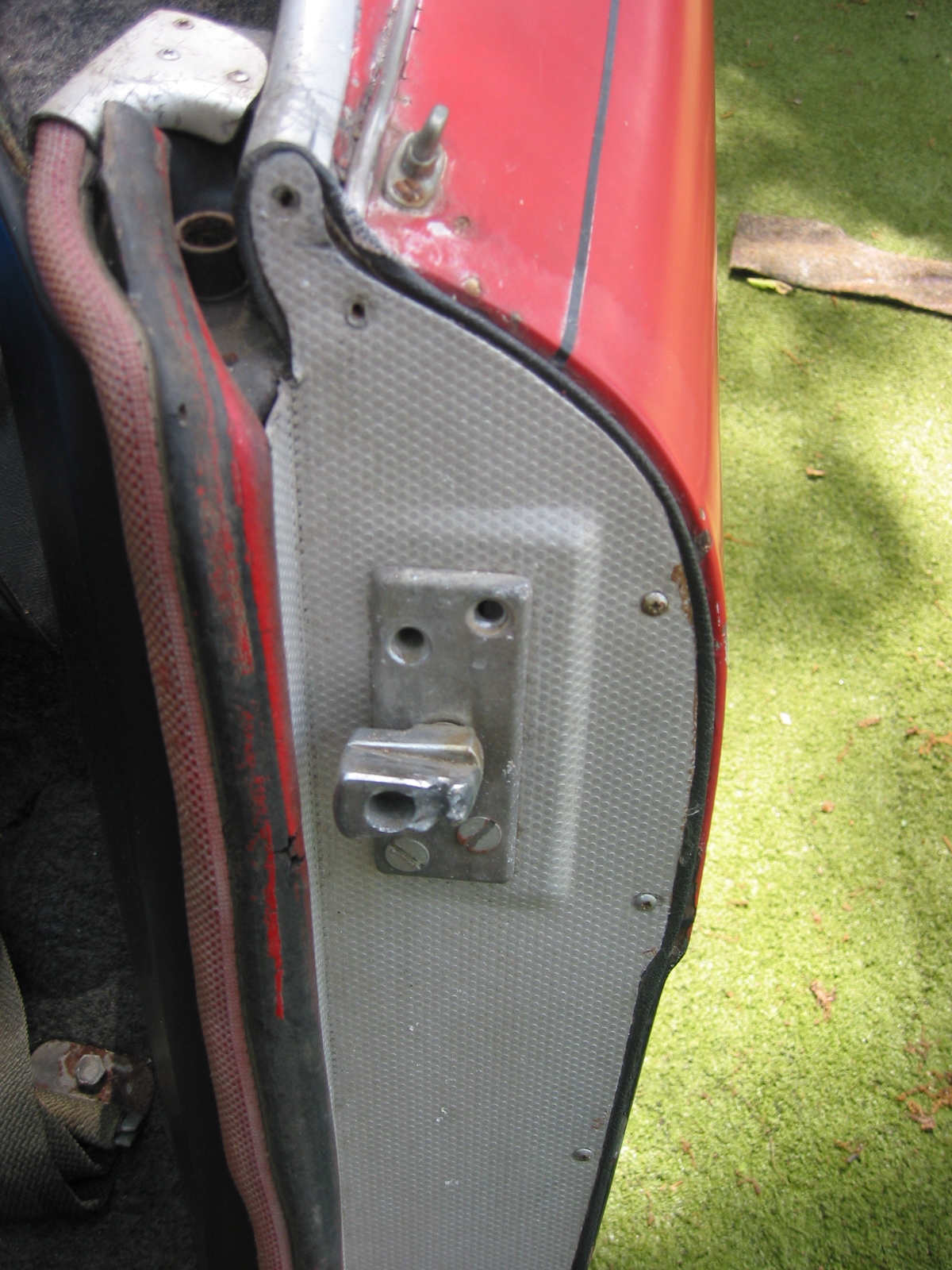
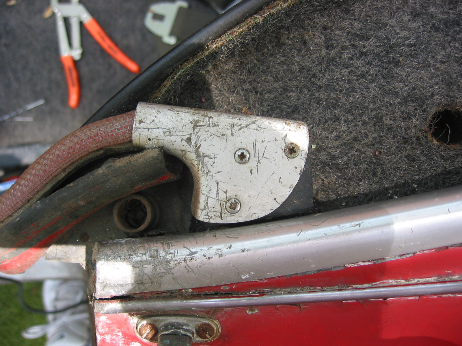
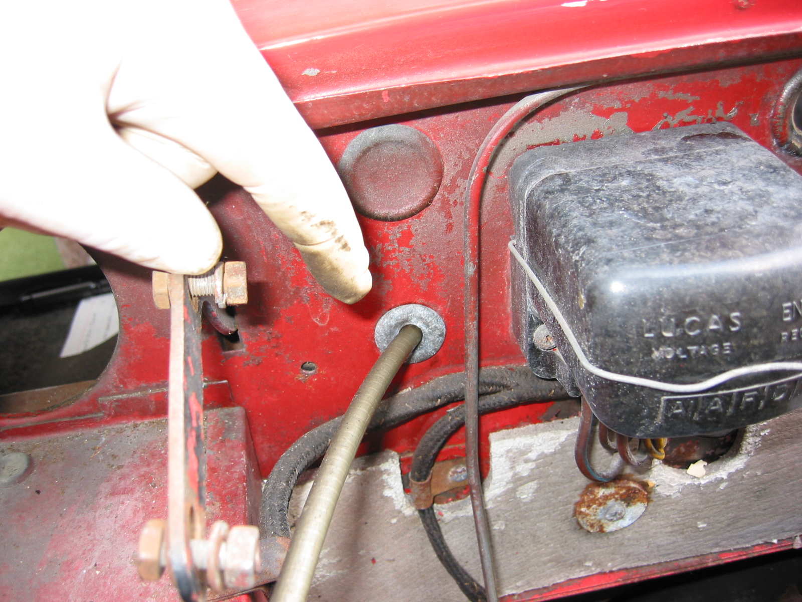
Steering Column Sealing Plate – Removed four sheet metal screws securing each of two sealing plates through which the steering column passes. Note the felt “gaskets” on the inside face of the plates.

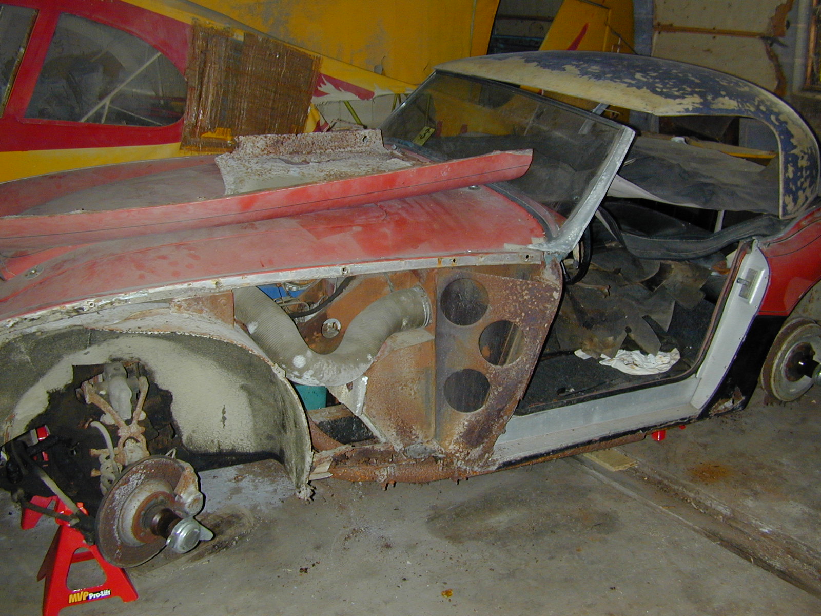
Front Suspension and Steering  

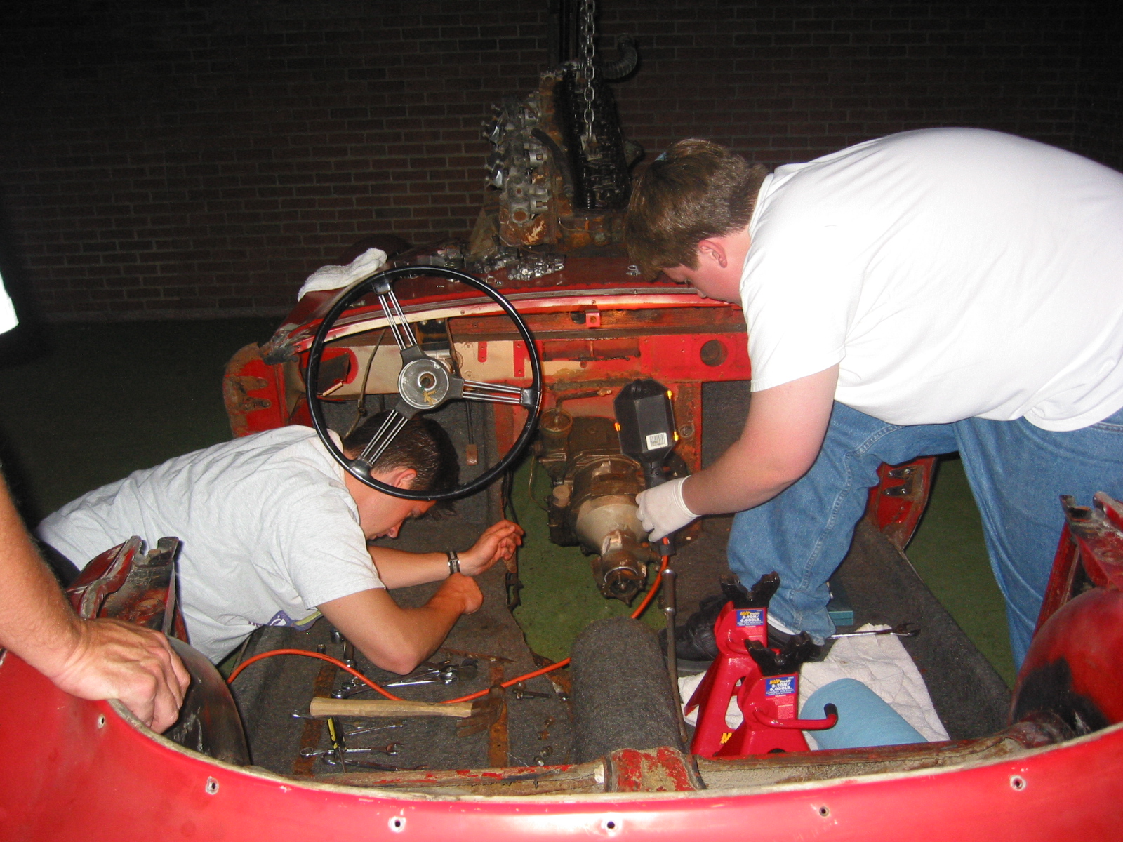
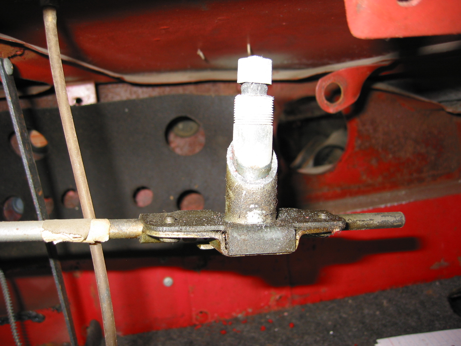
The disassembly of the front suspension and steering assembly was a messy job. Lots of grease and grime built up over the years. I first jacked up the car. Disconnected the cross tube and side rods from the steering levers. The cross tube was 5/16” from the side to the nuts. Released cotter pins and took lever arms off. Used a fork and hammer to free the ball joints from the side rods at the inner and outer connections. Pulled the rods off.

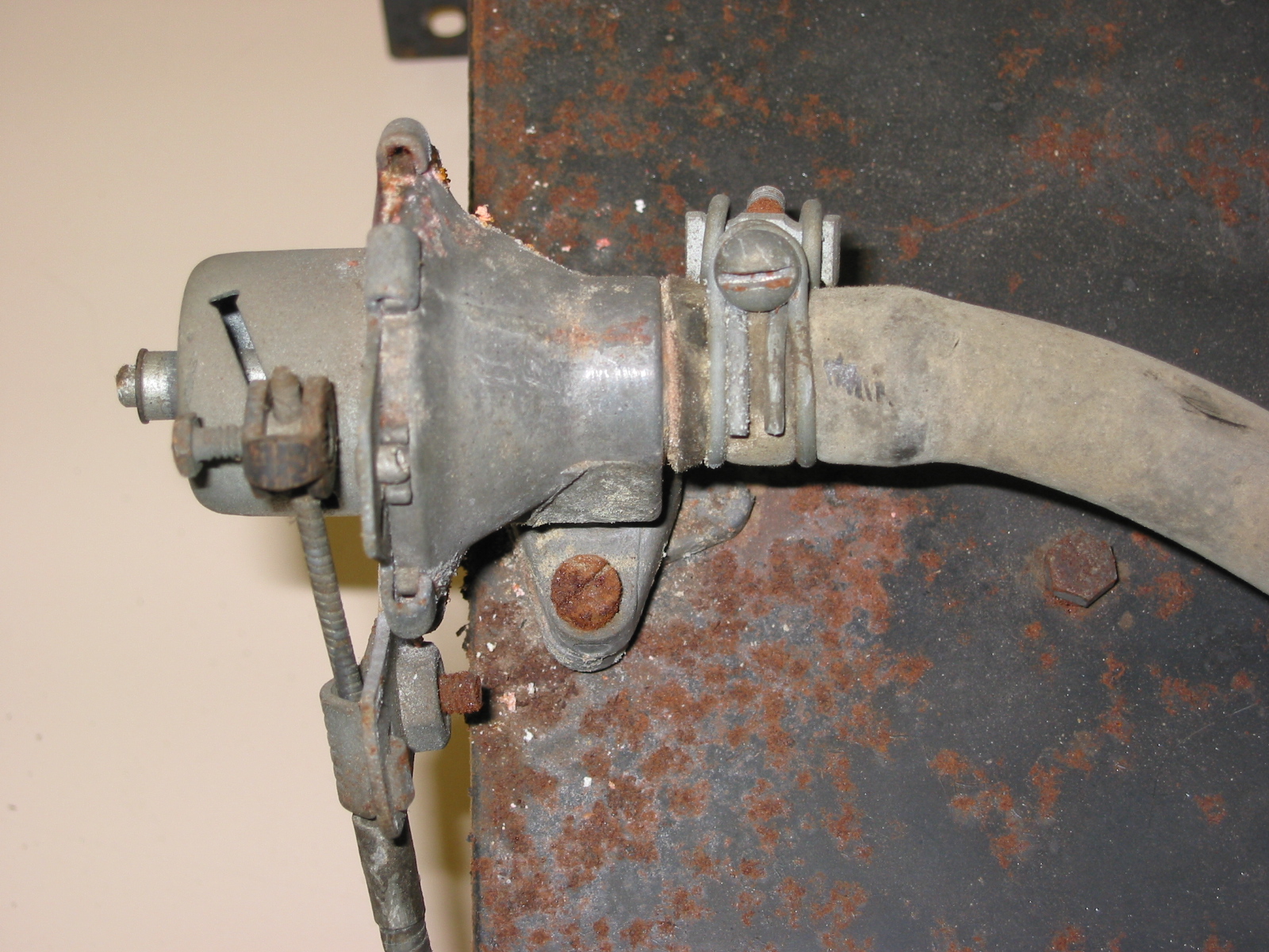
Stub Axle Carrier, King Pin, Caliper, Dust Shield

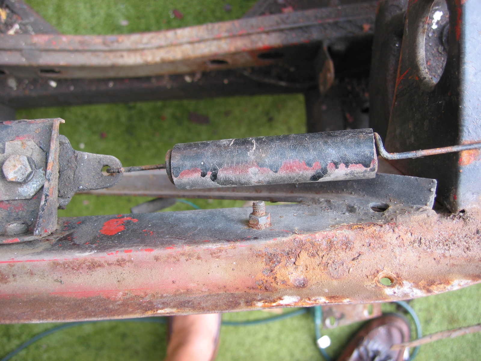
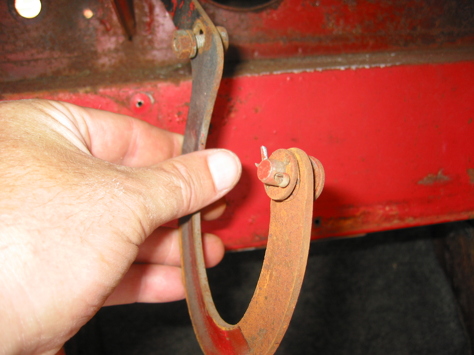
Cross Tube, Ball Joint, Steering lever and Side Rod
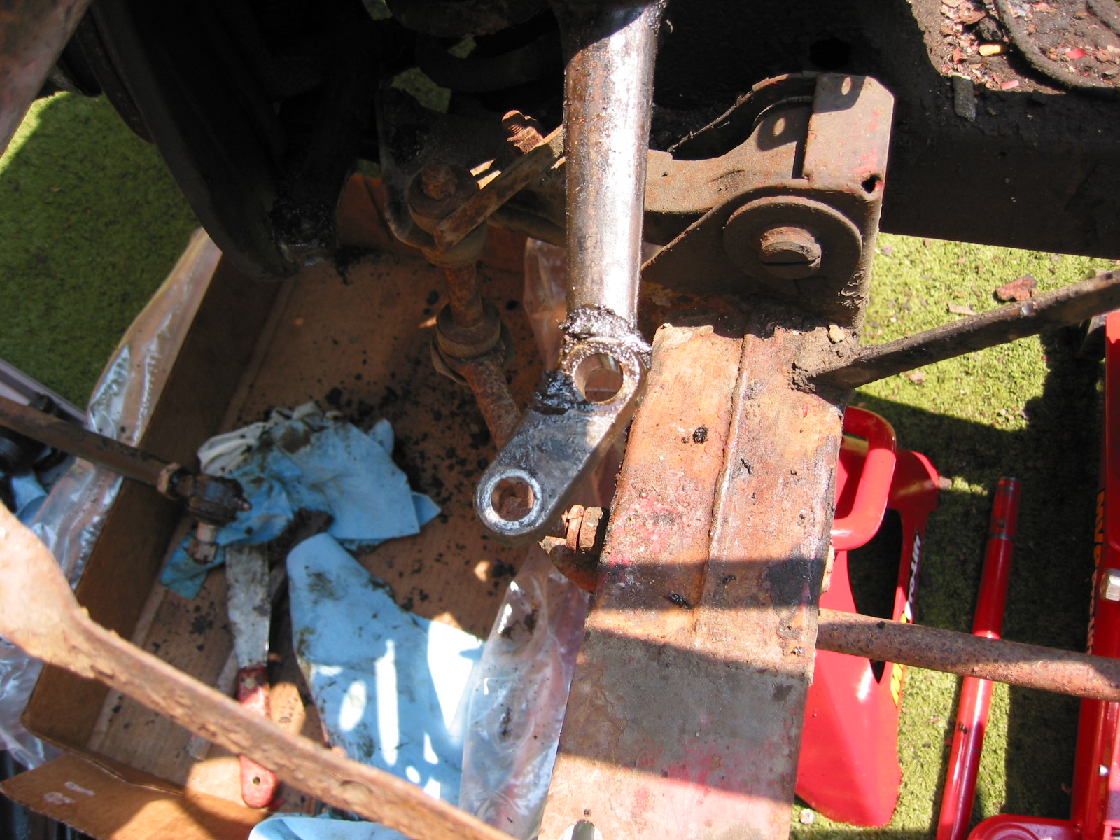
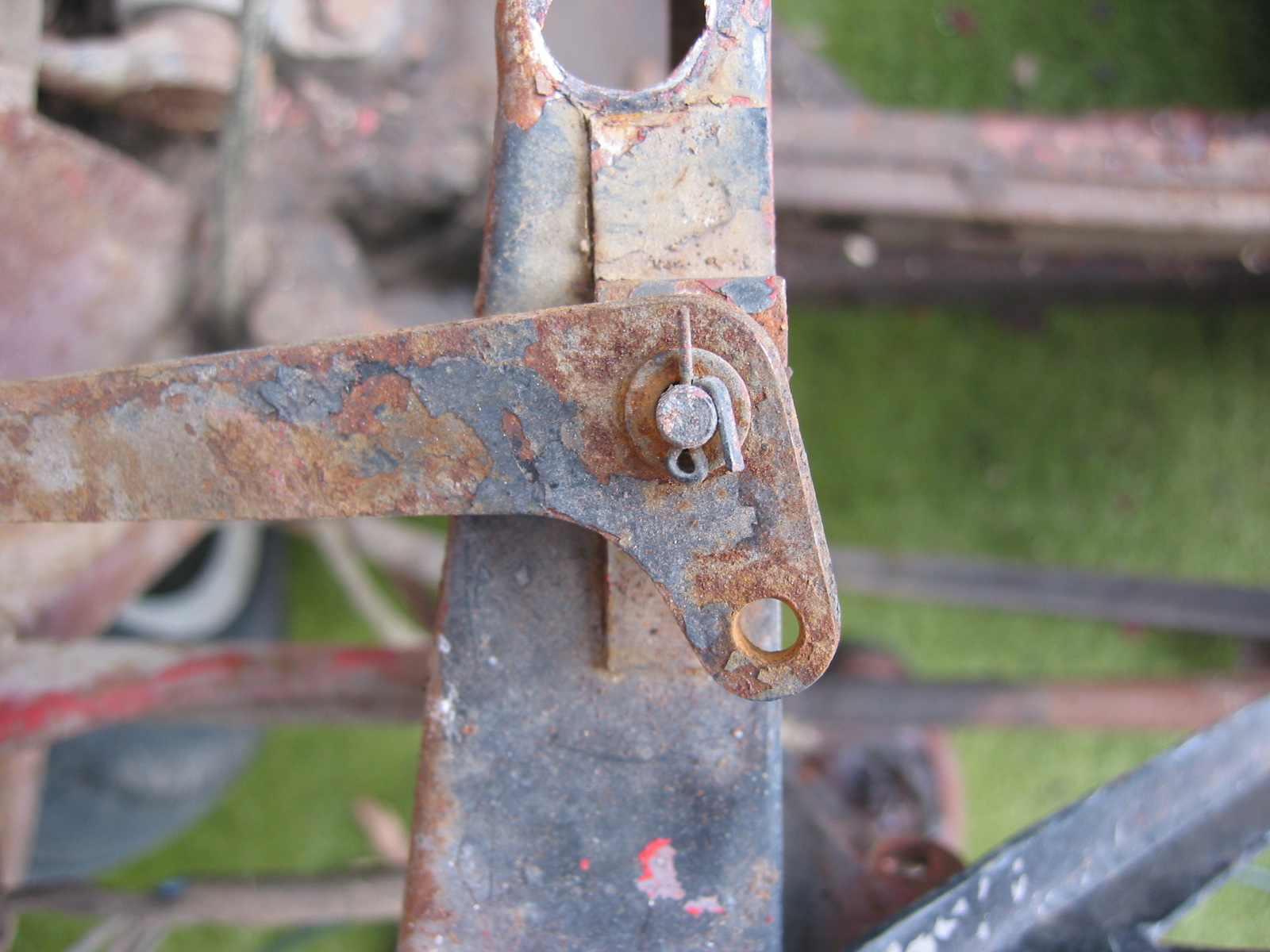
RH Steering Lever

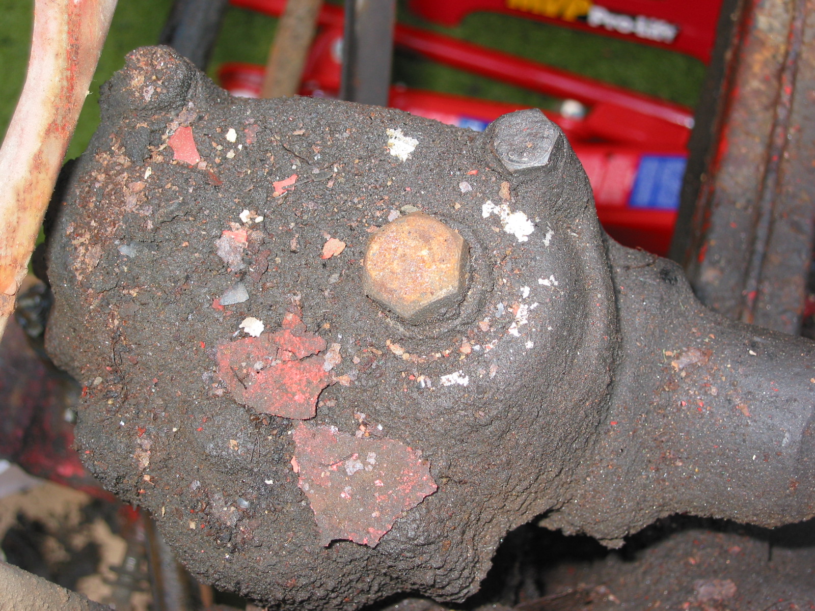
Stub Axle Carrier, King pin, Dust Shield

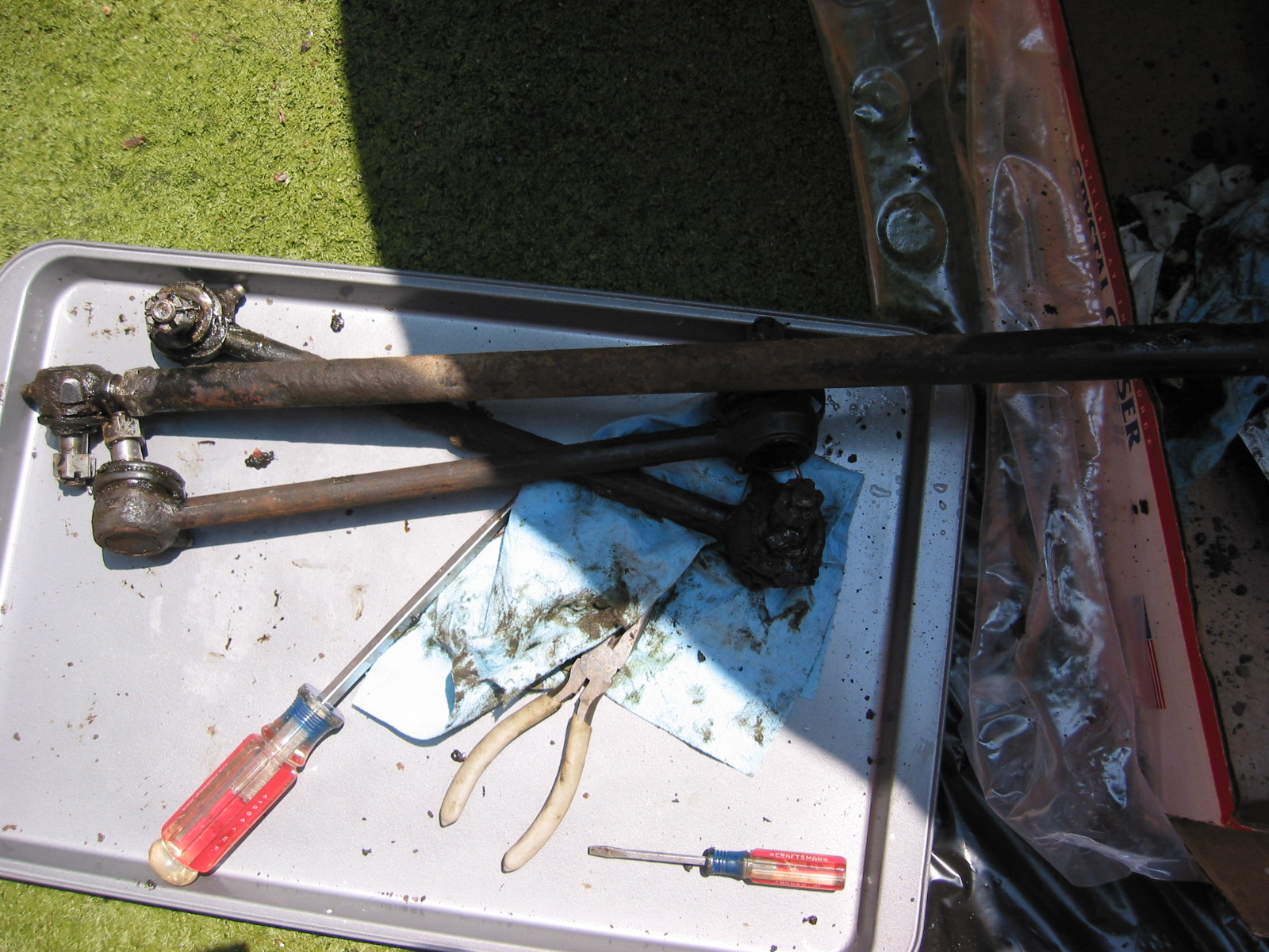
Cross Tube and Side rods
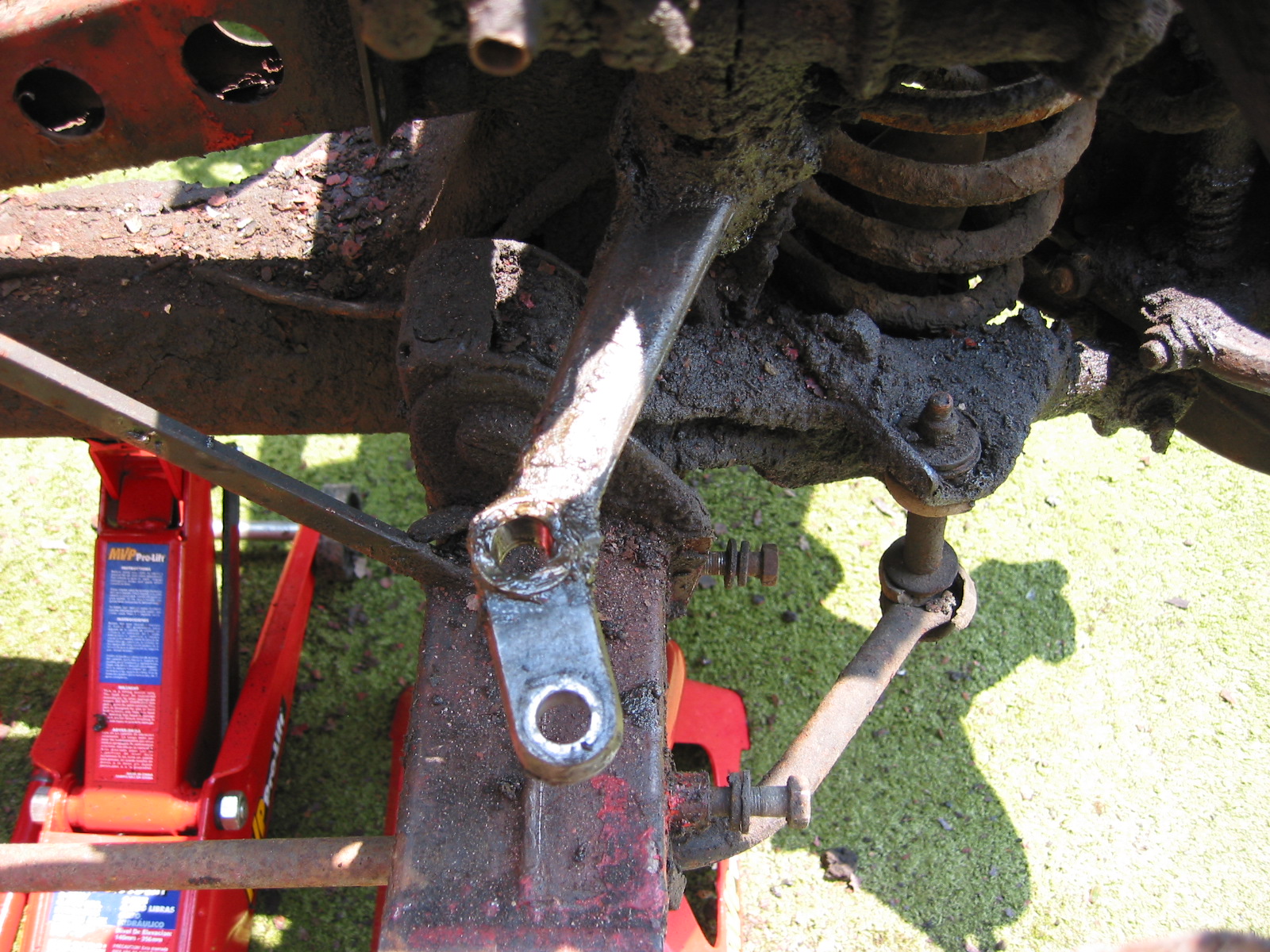
LH Steering Lever

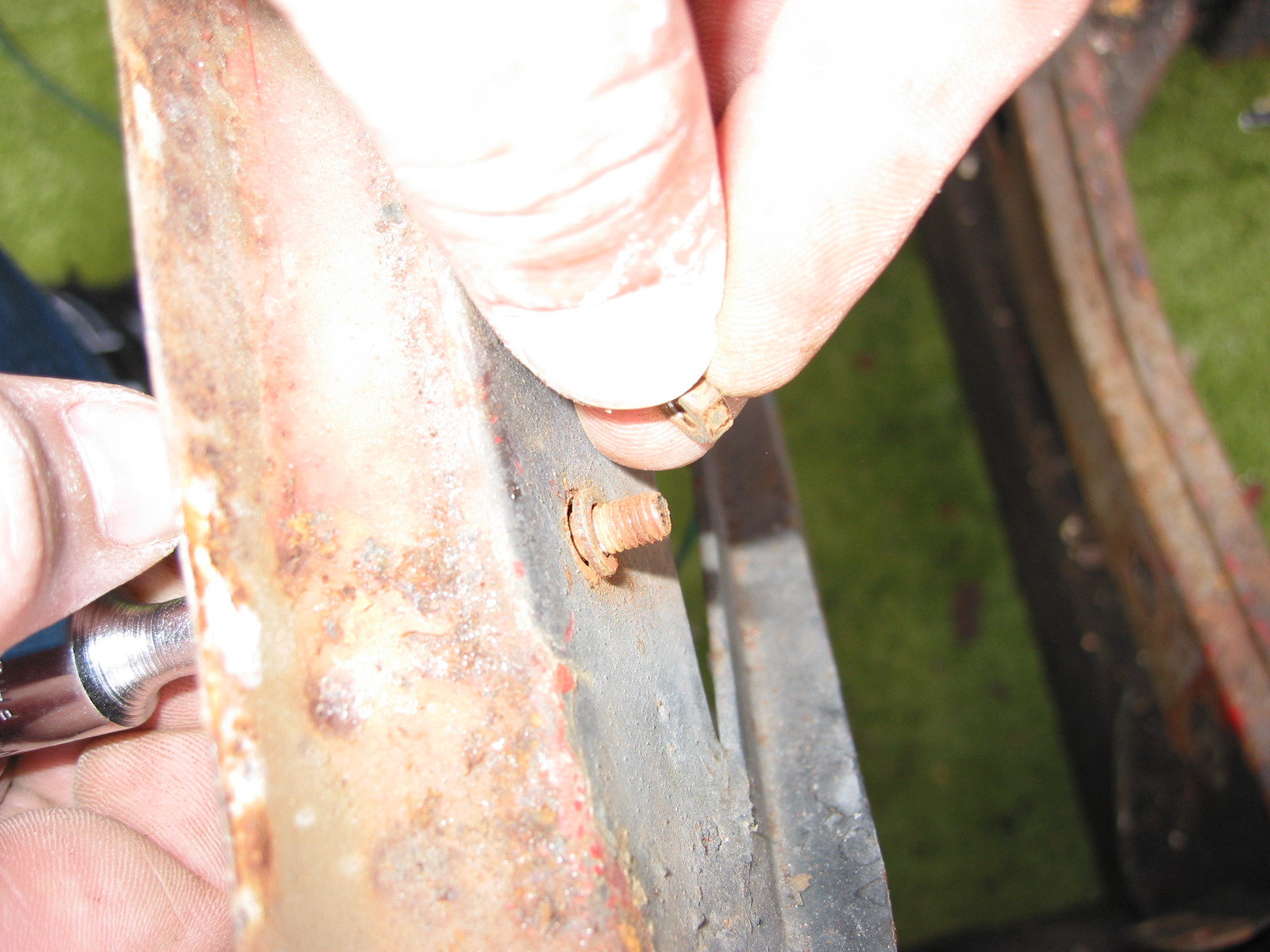
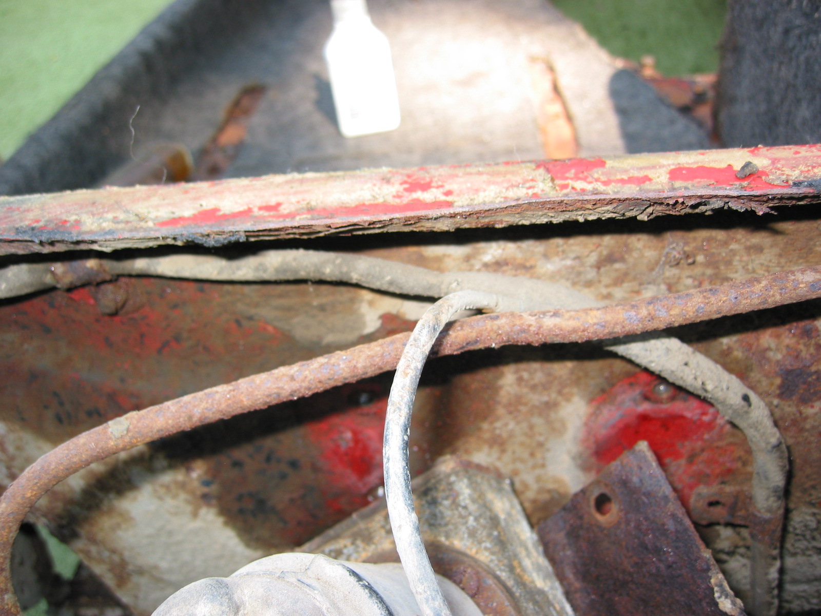
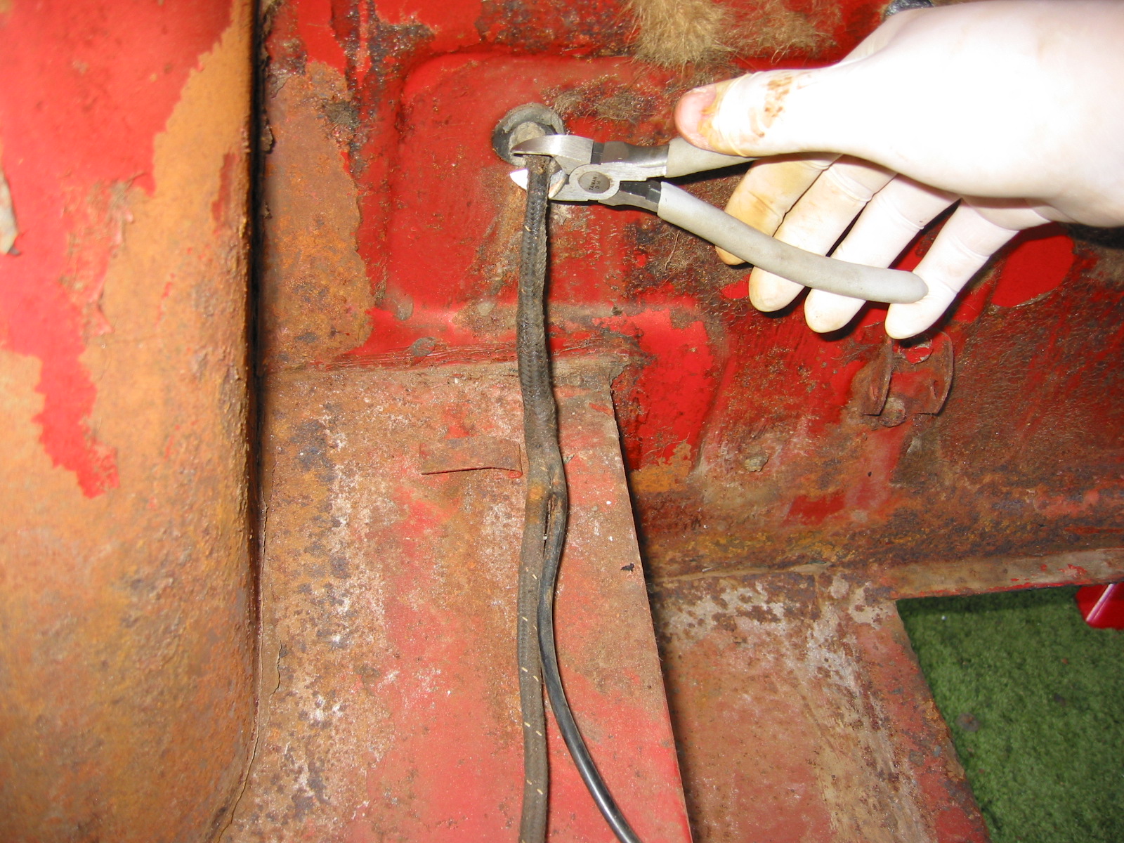
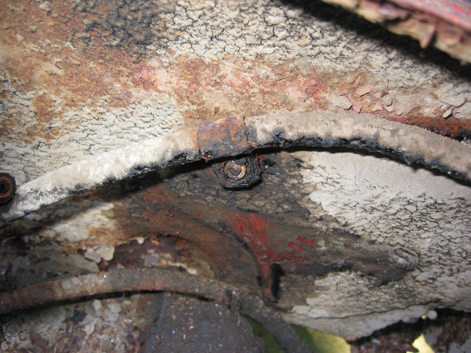
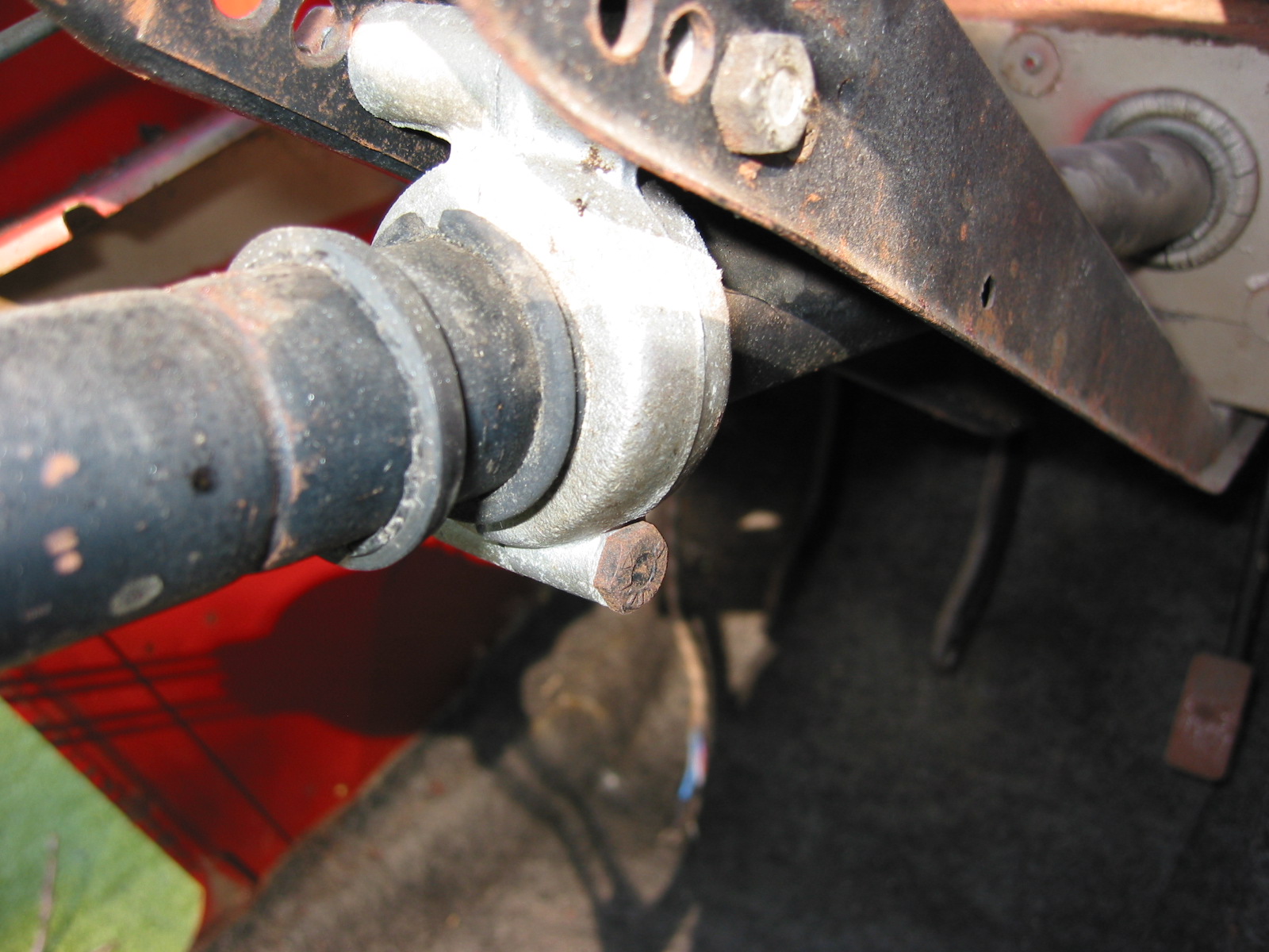
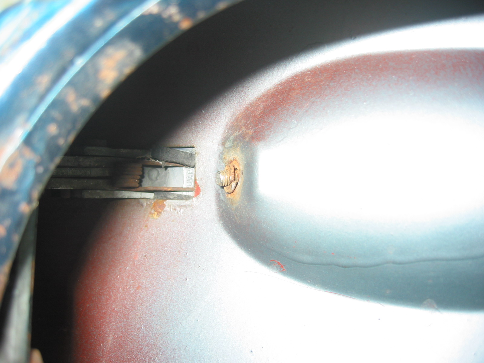
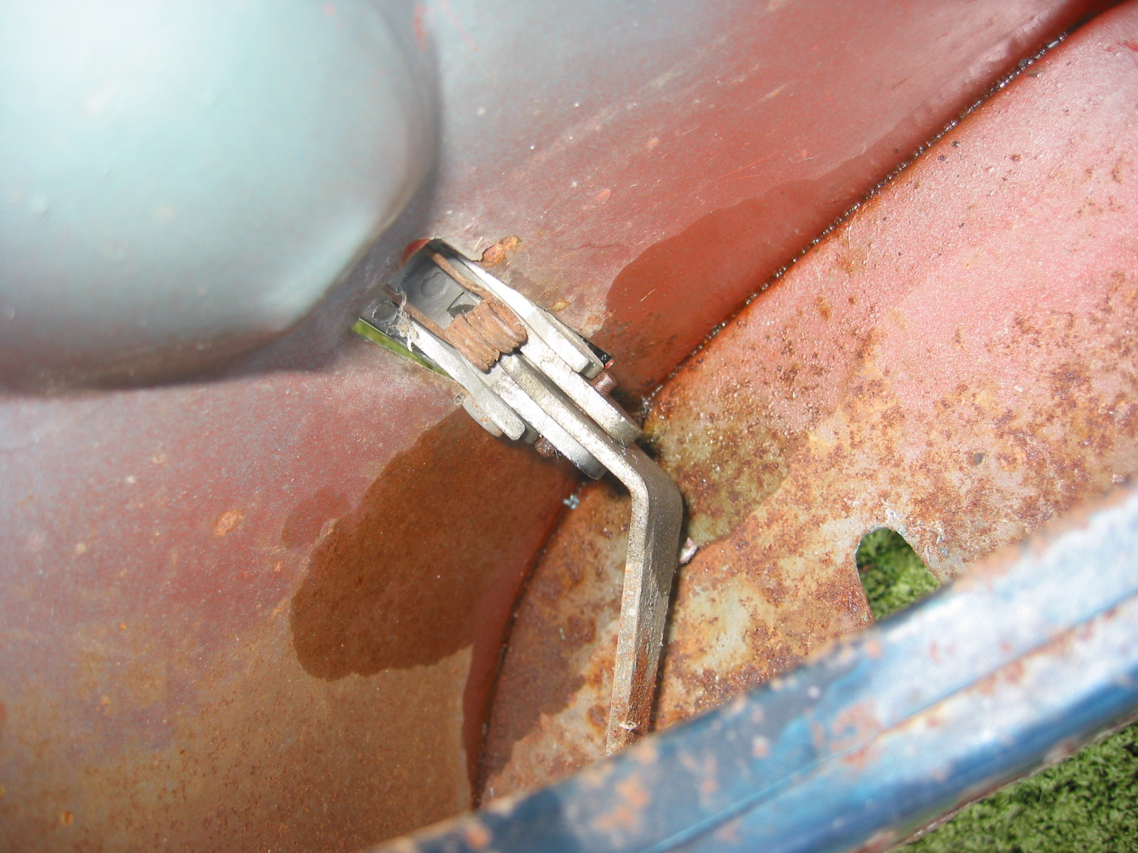
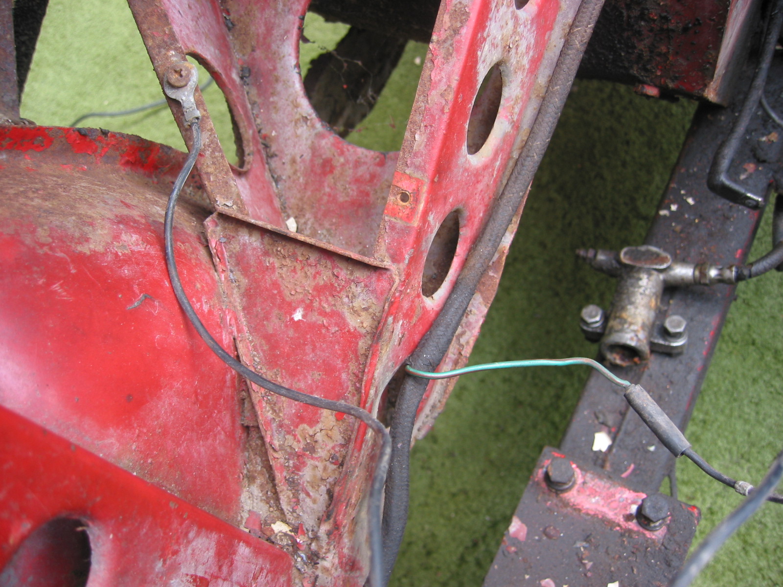
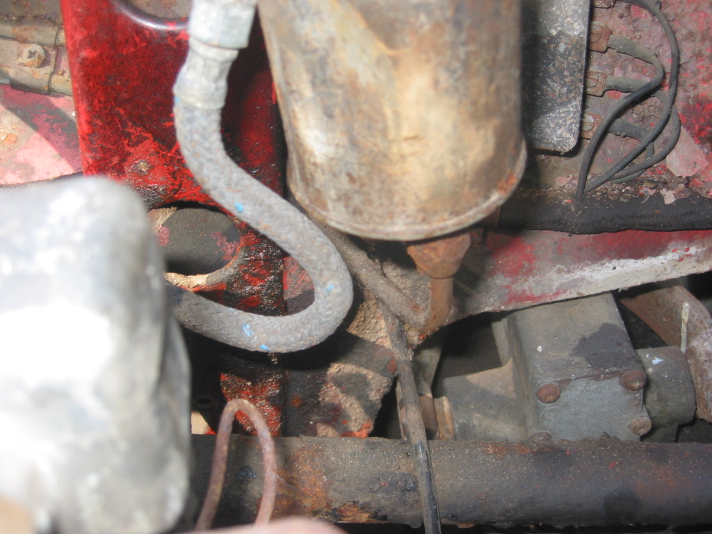
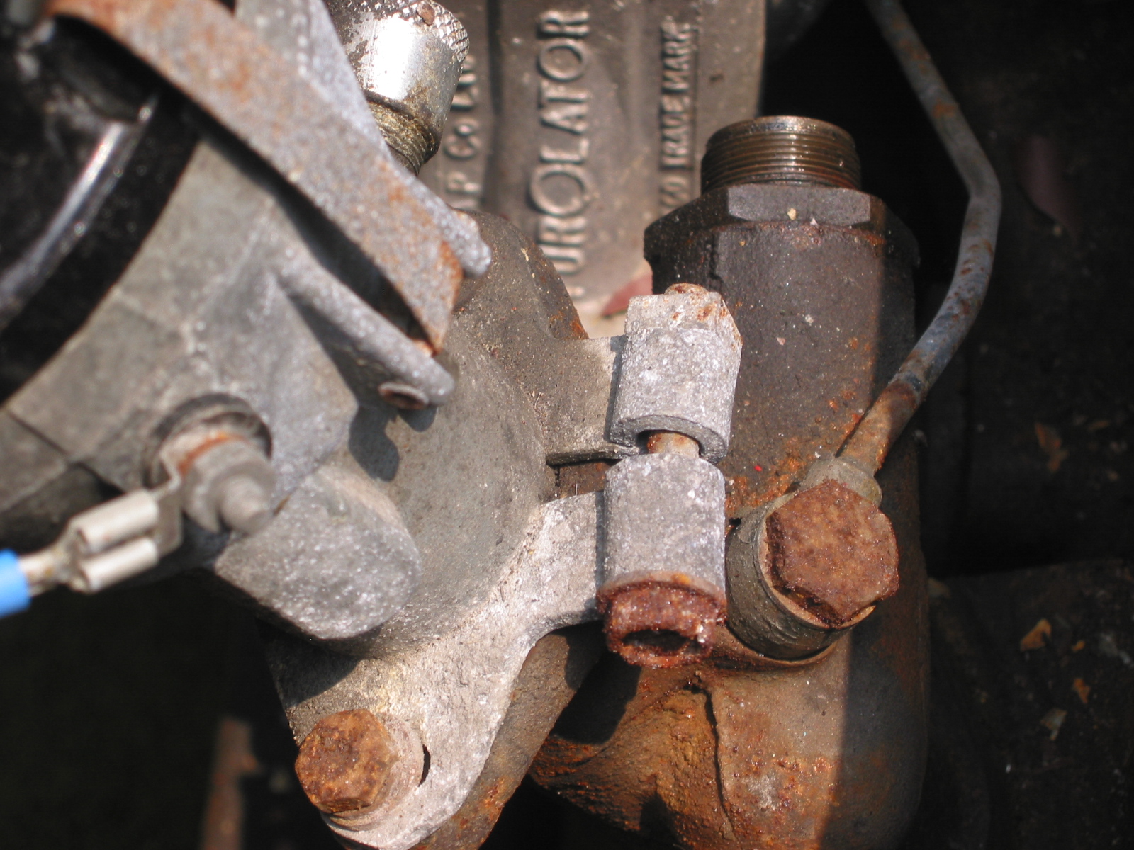
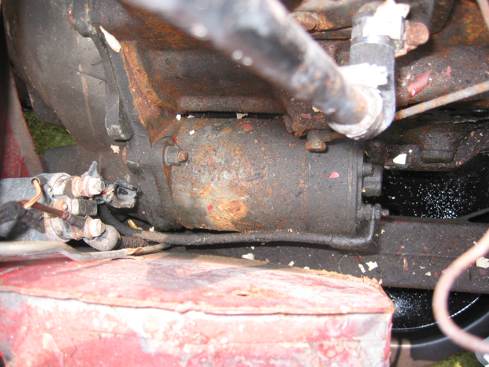
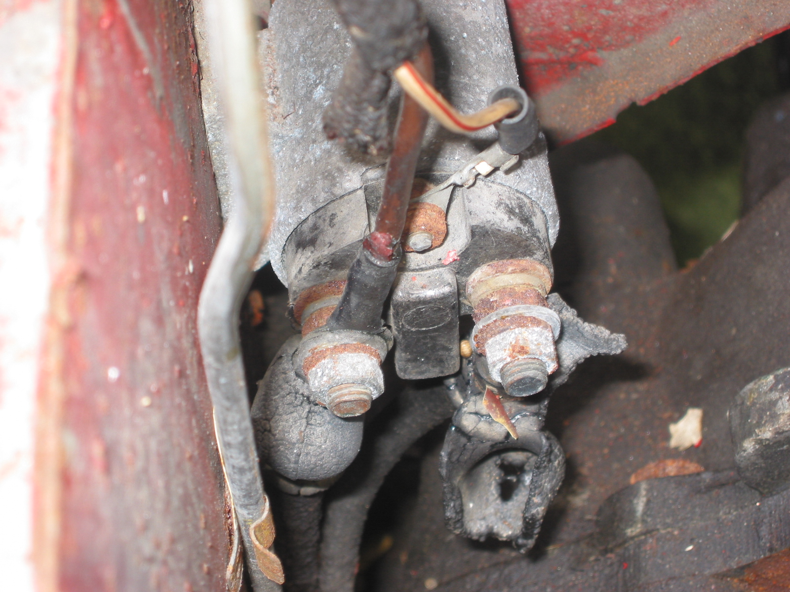
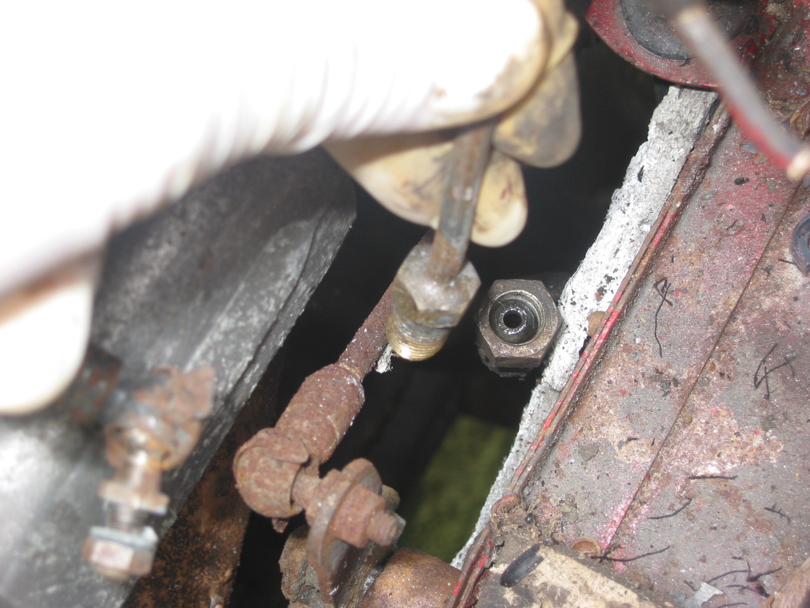
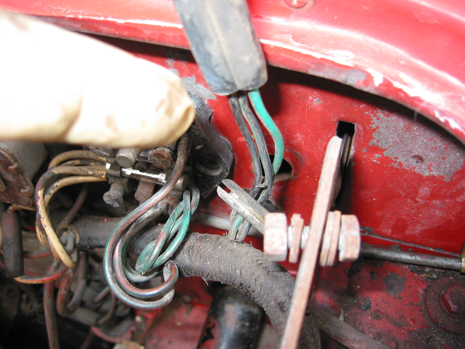
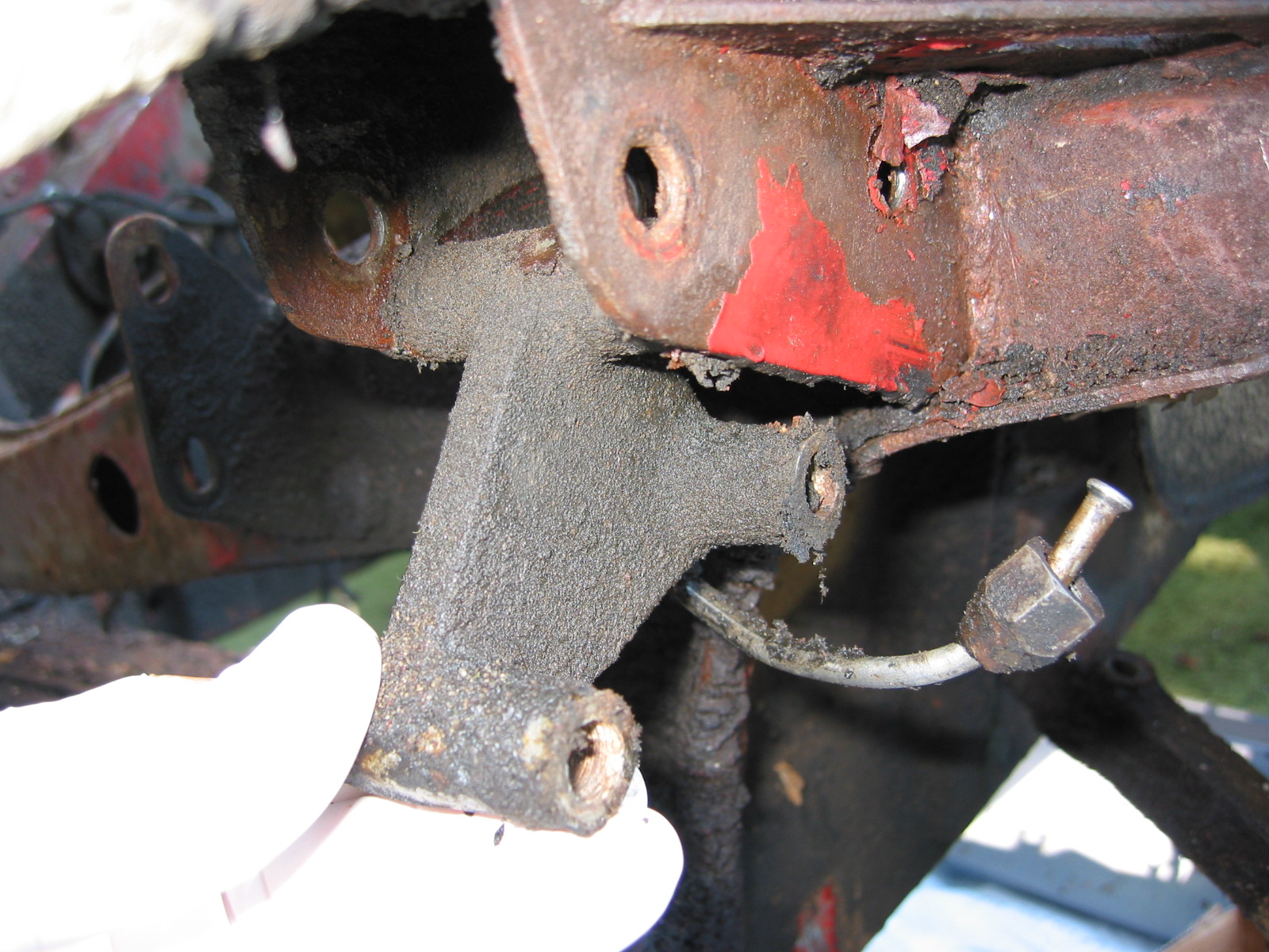
Cross Tube Ball Joints –  were removed by repeating the same action as above. Unscrewed the mounting bolts from the steering box. This requires removing the 7/16” bolt that secures the left brake flexible fluid hose. 

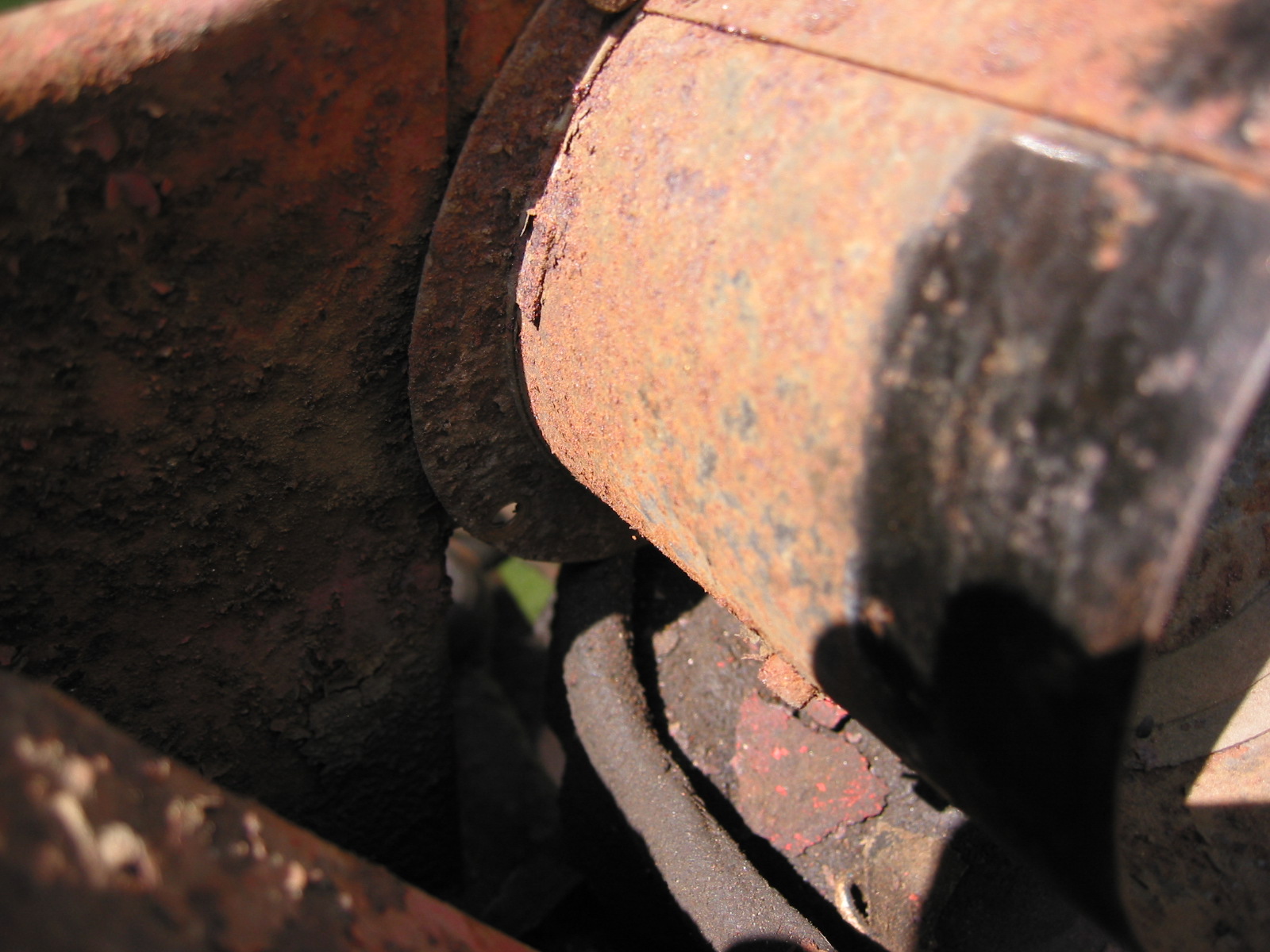
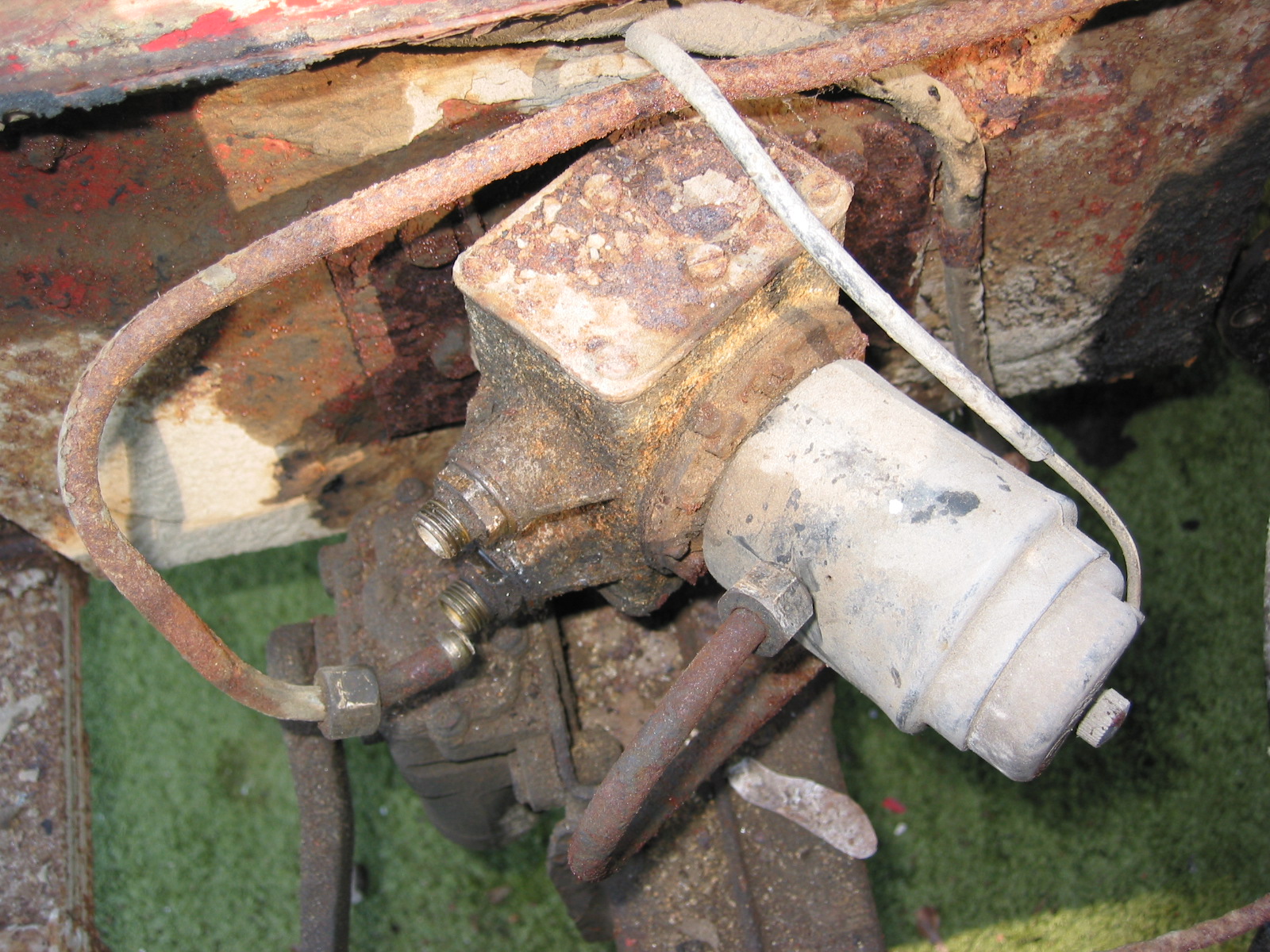
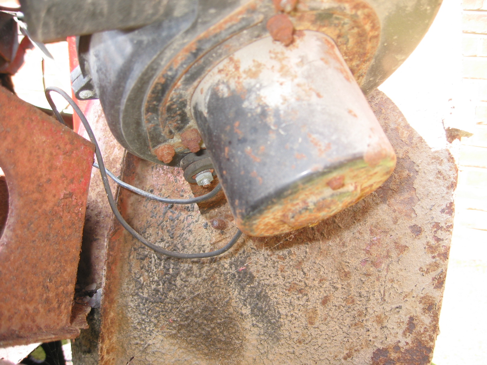
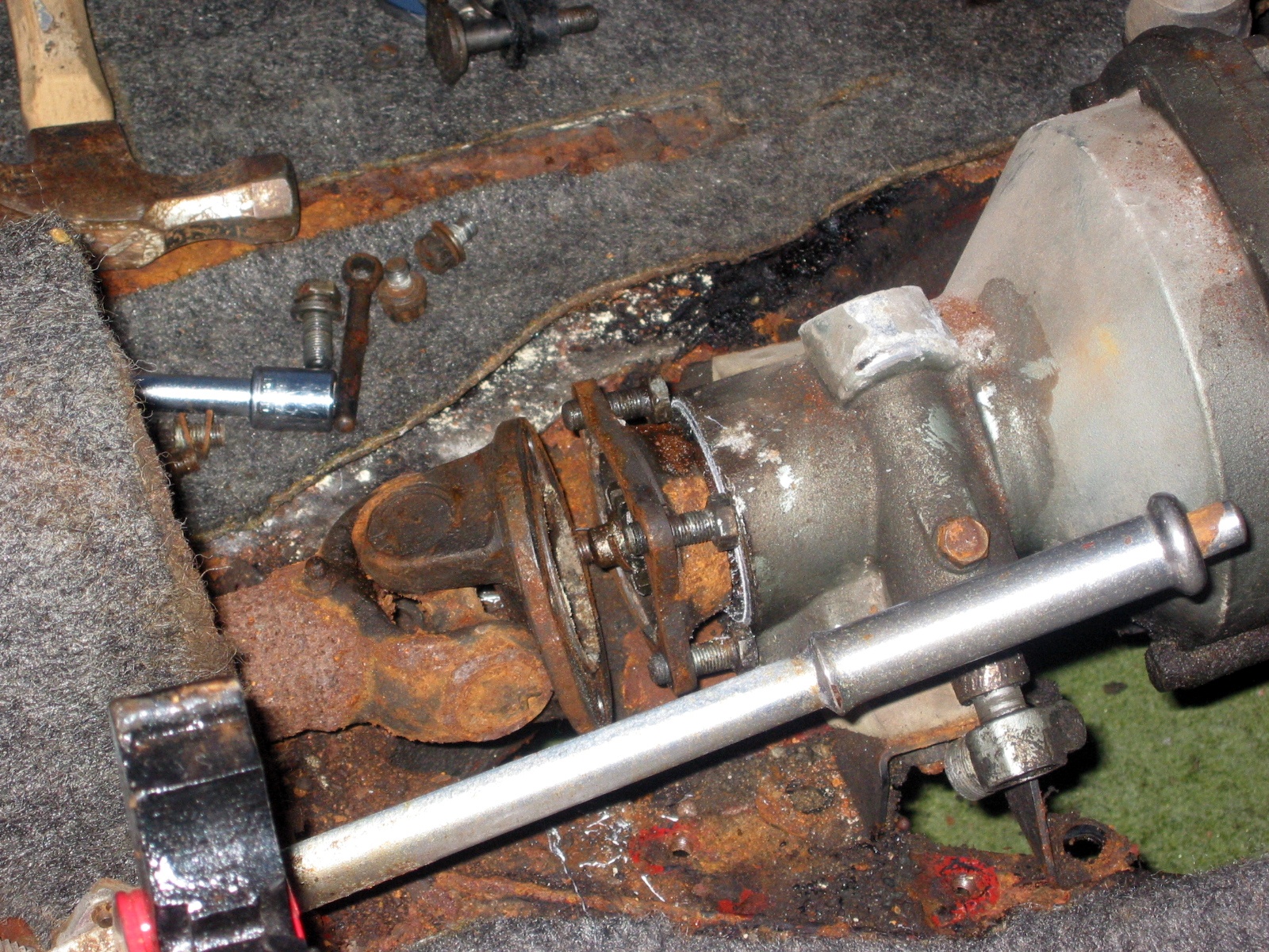
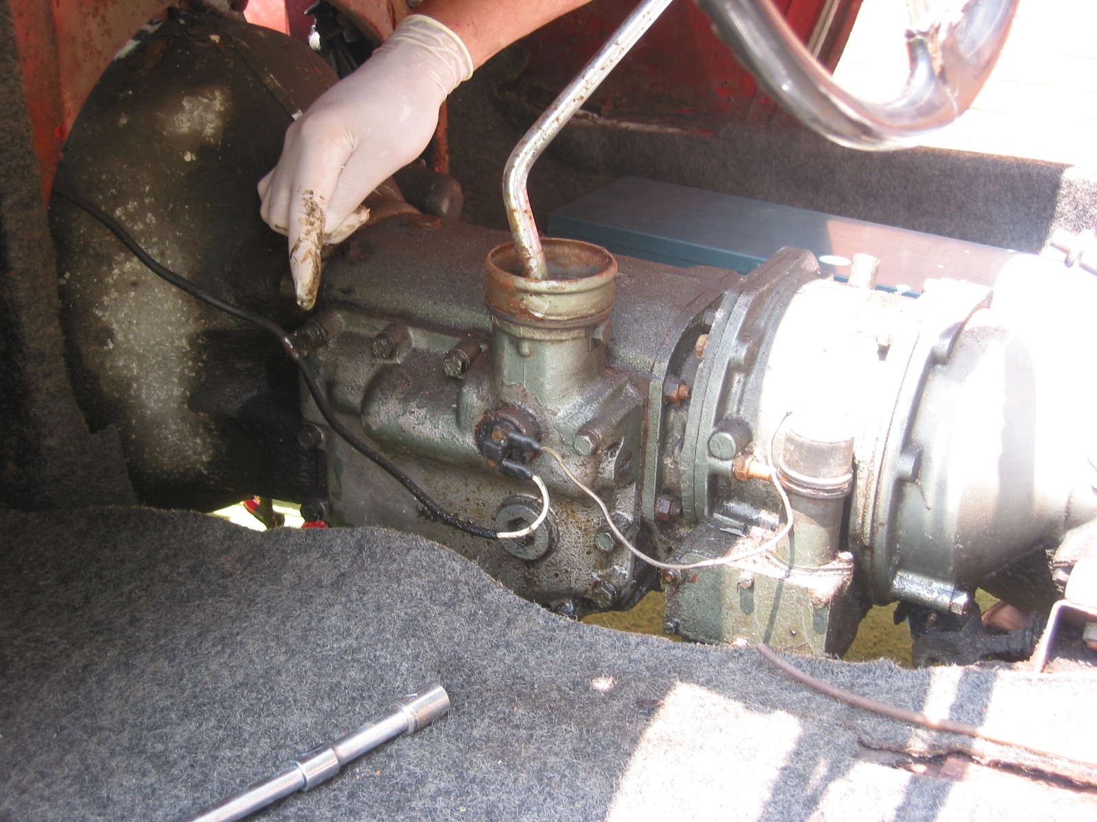
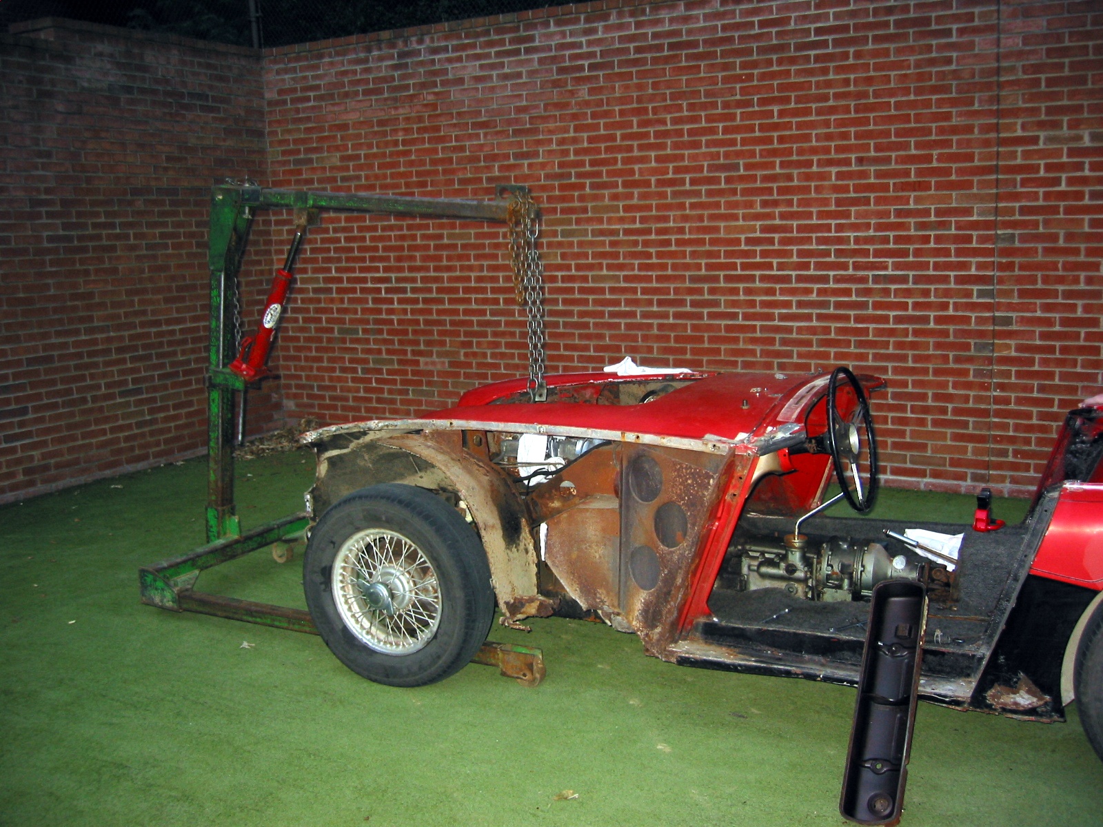
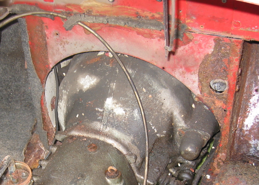
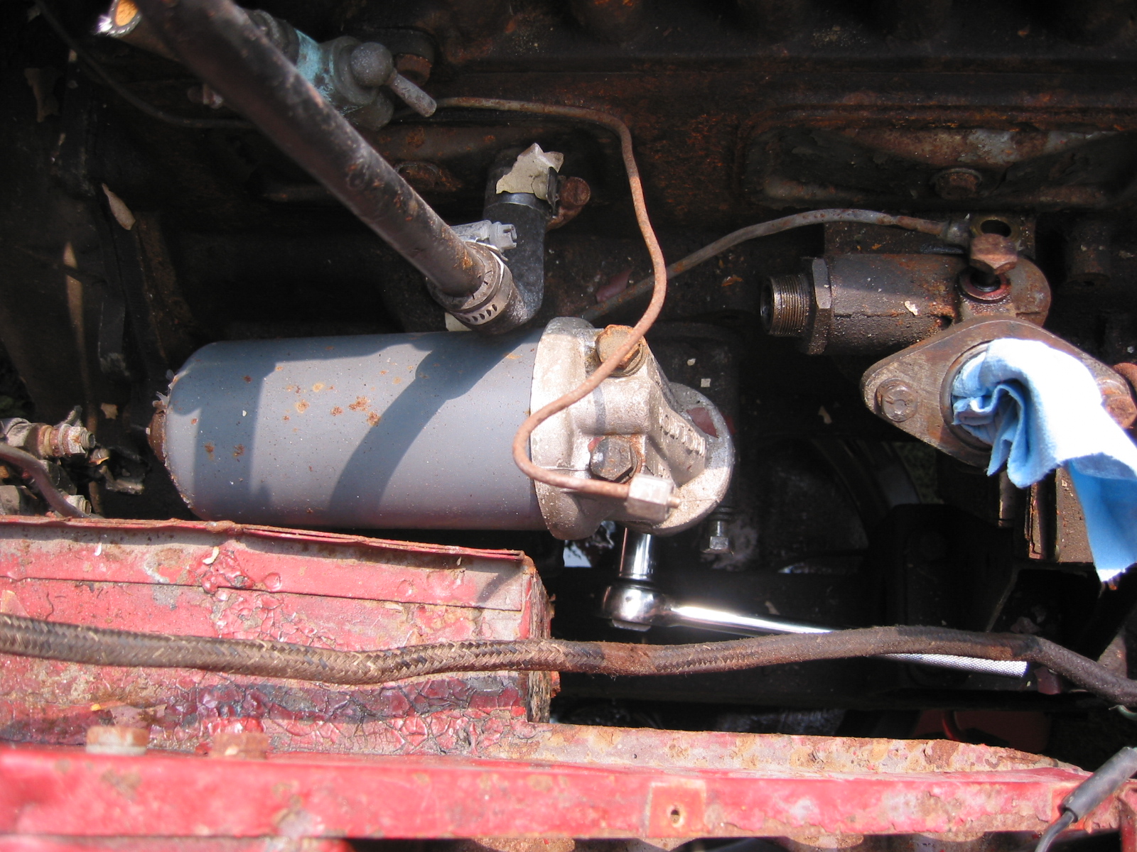
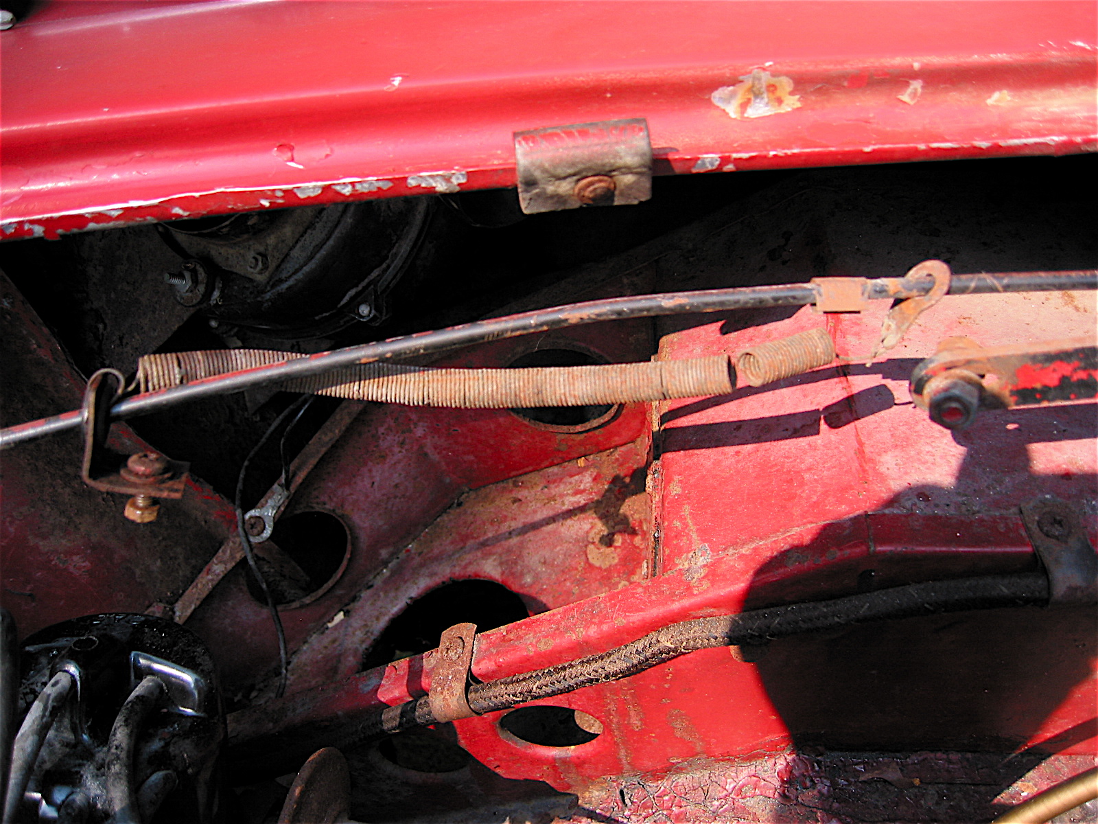
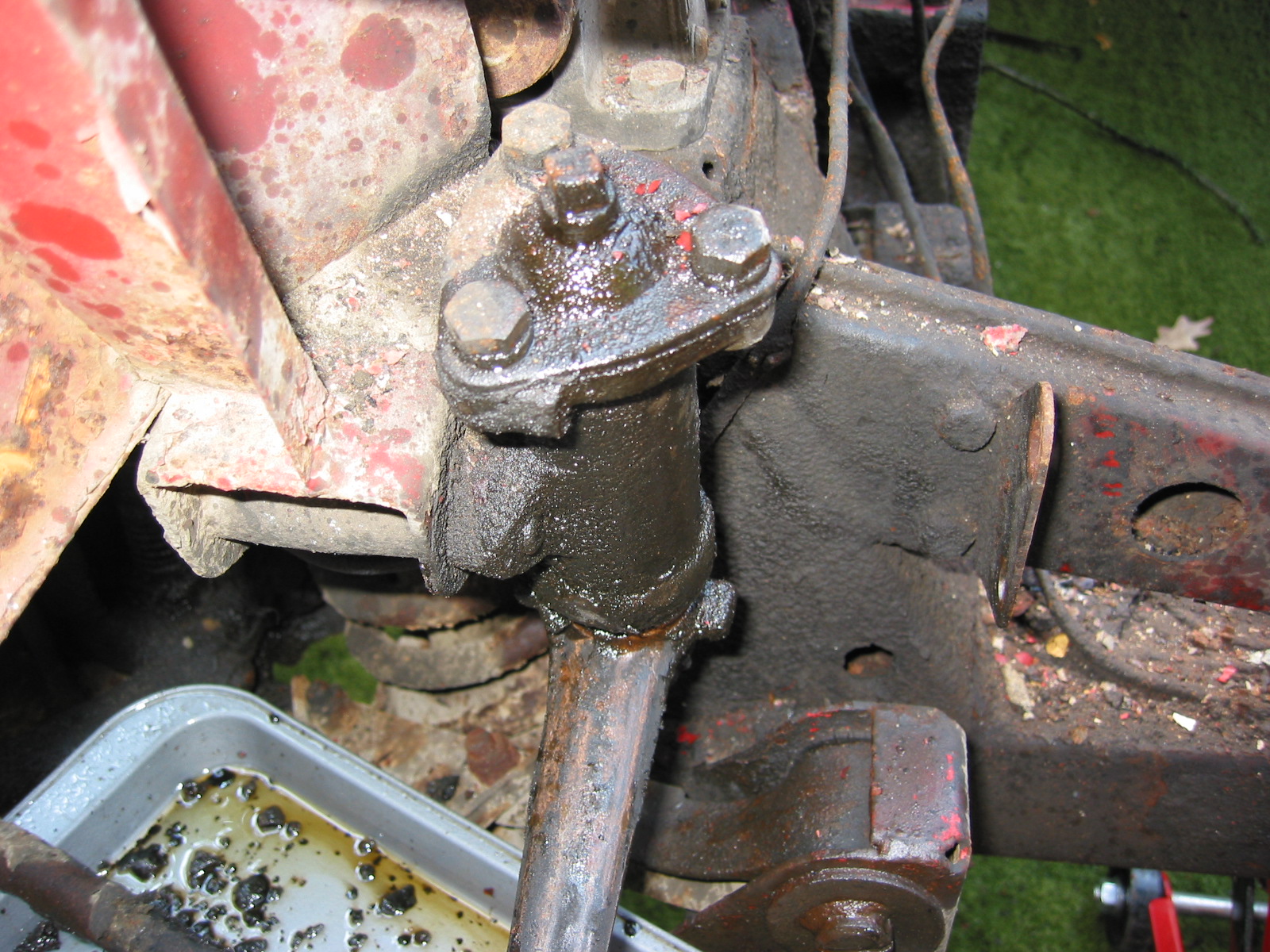
Steering box – After removing the mounting bolts, the box and rod can be pulled out through the front of the car.

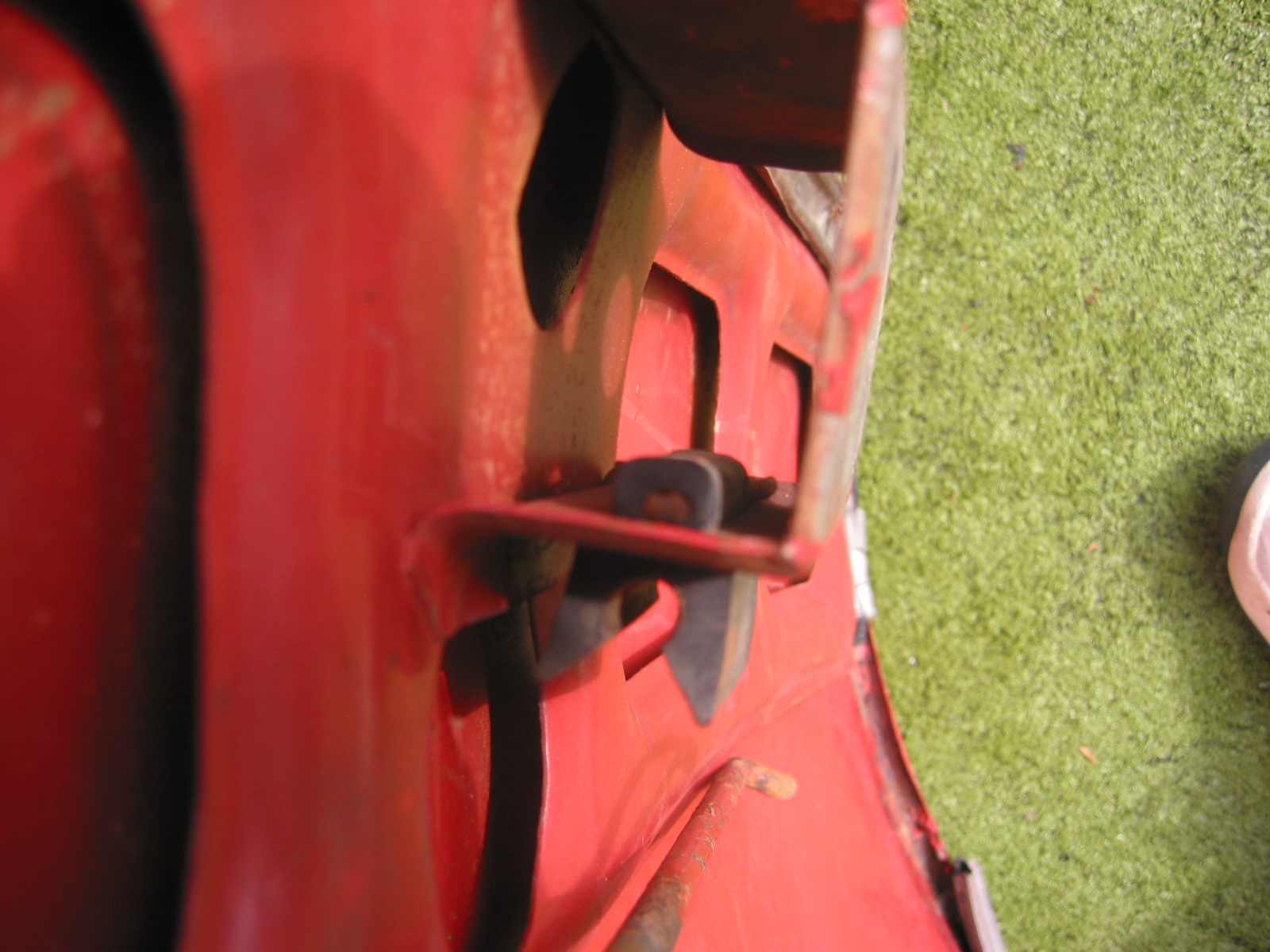
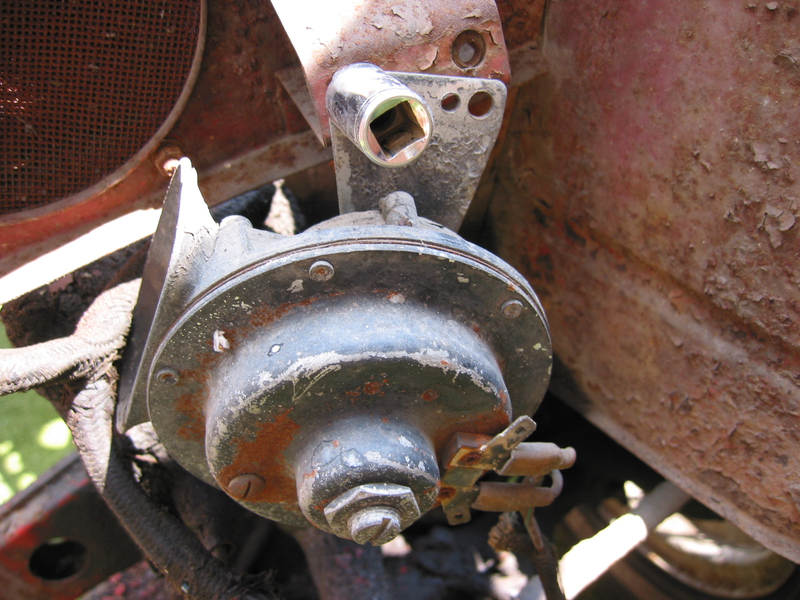
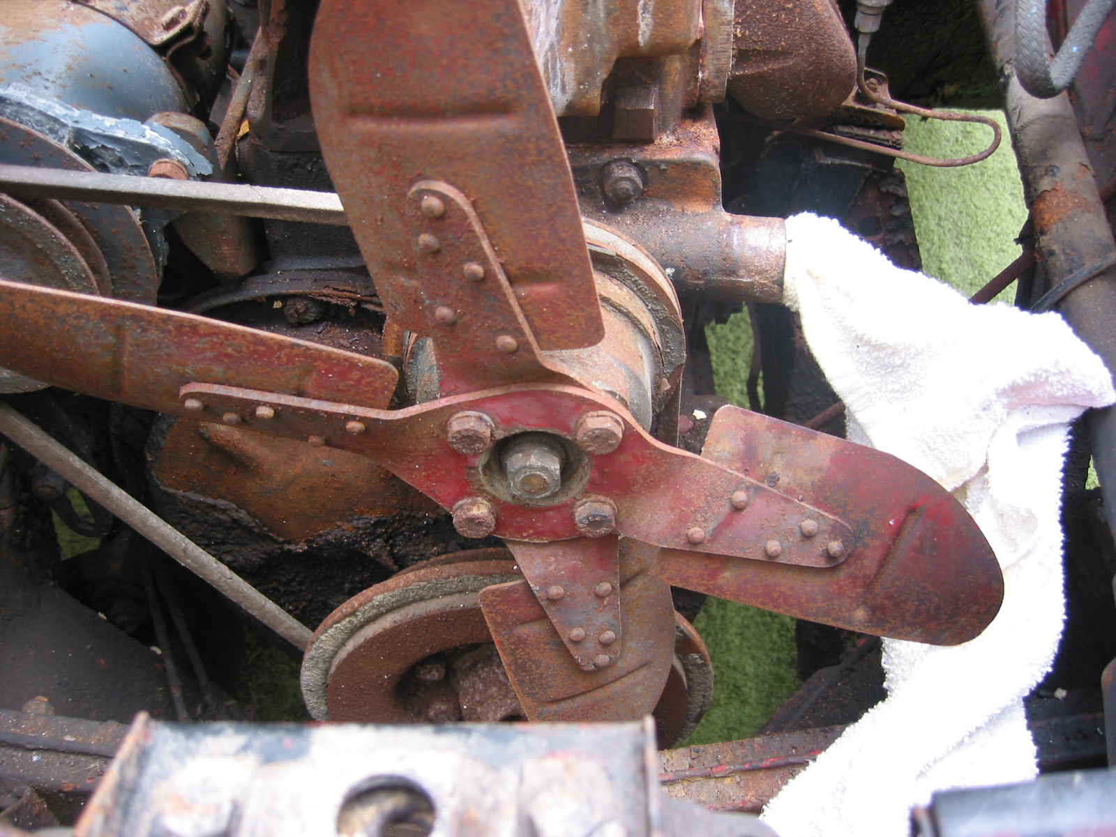
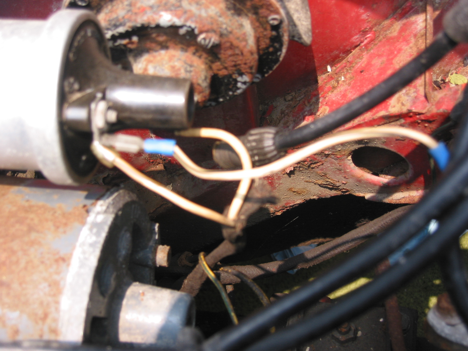
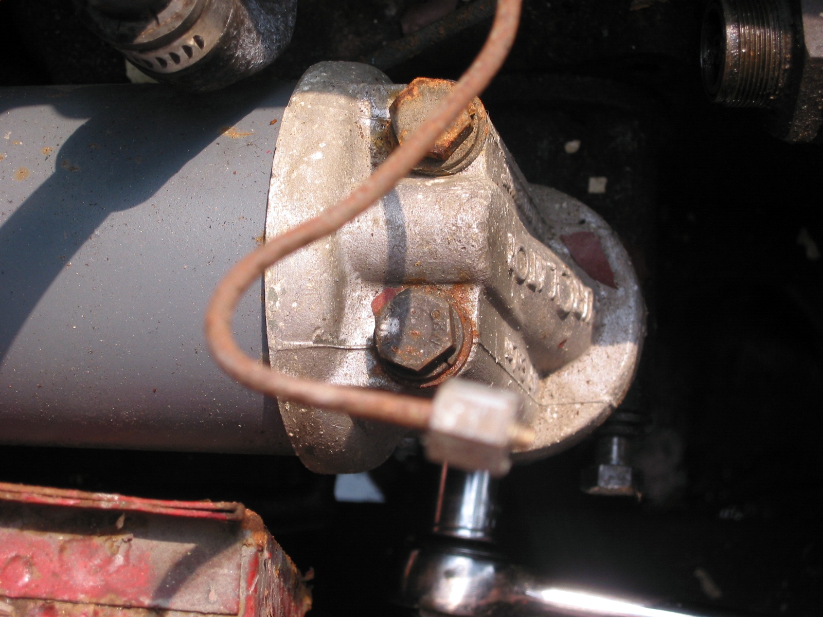
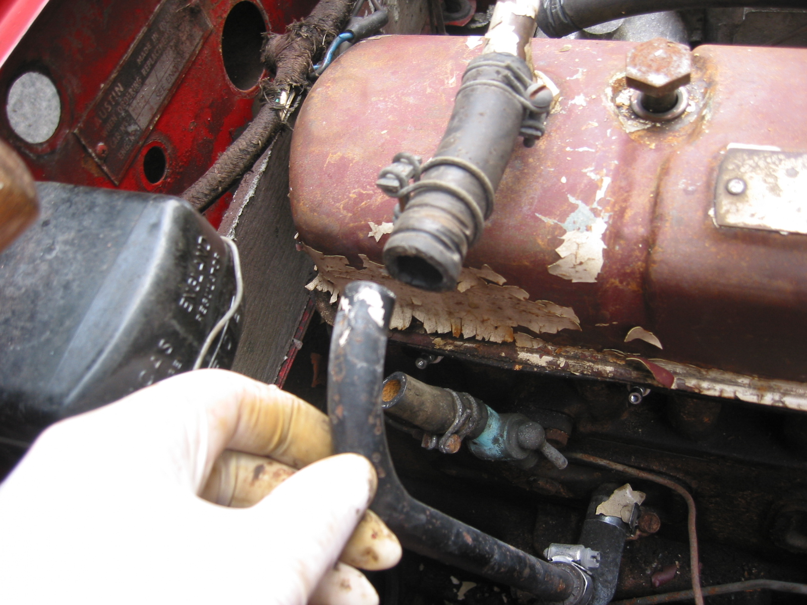
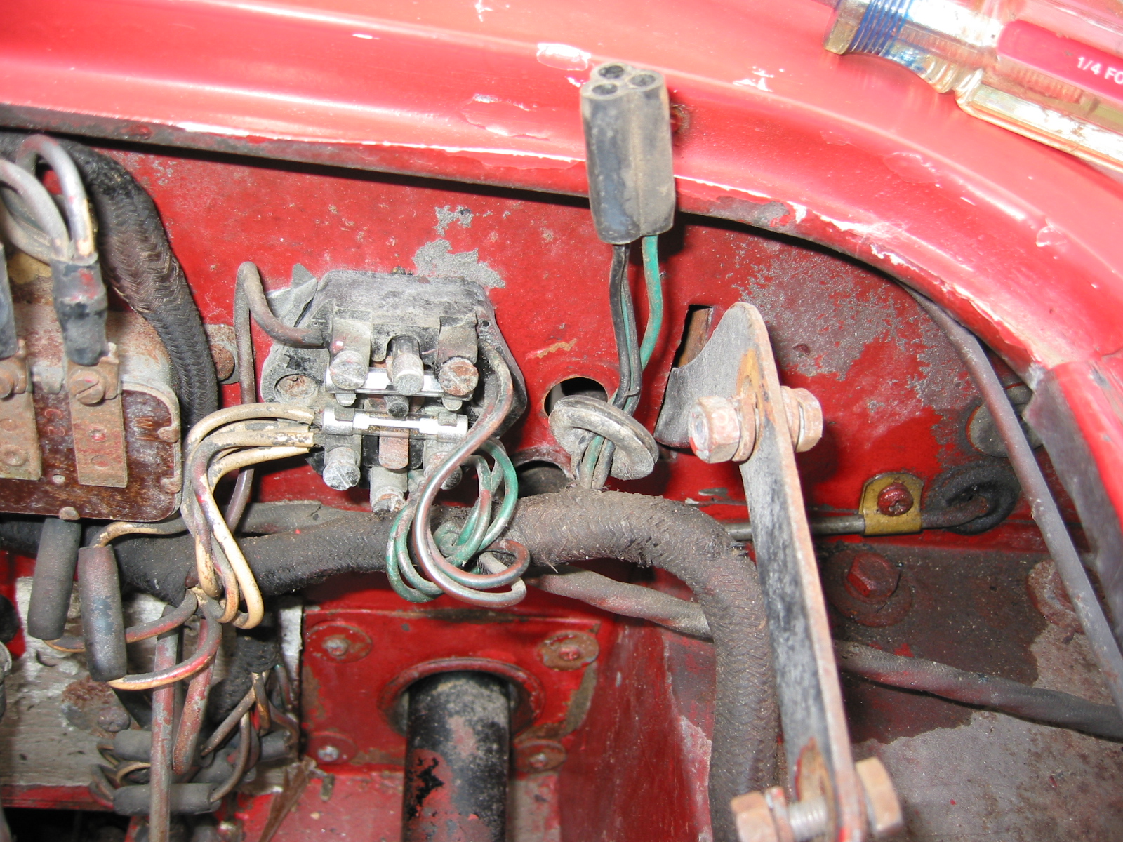
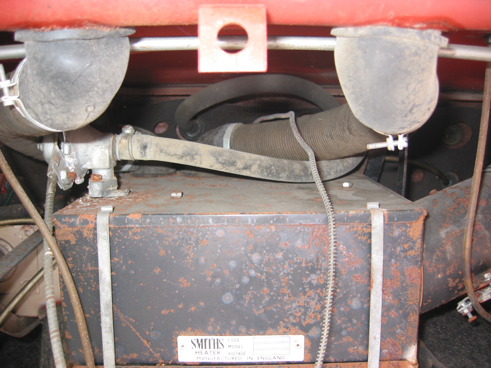
Steering Box in Place

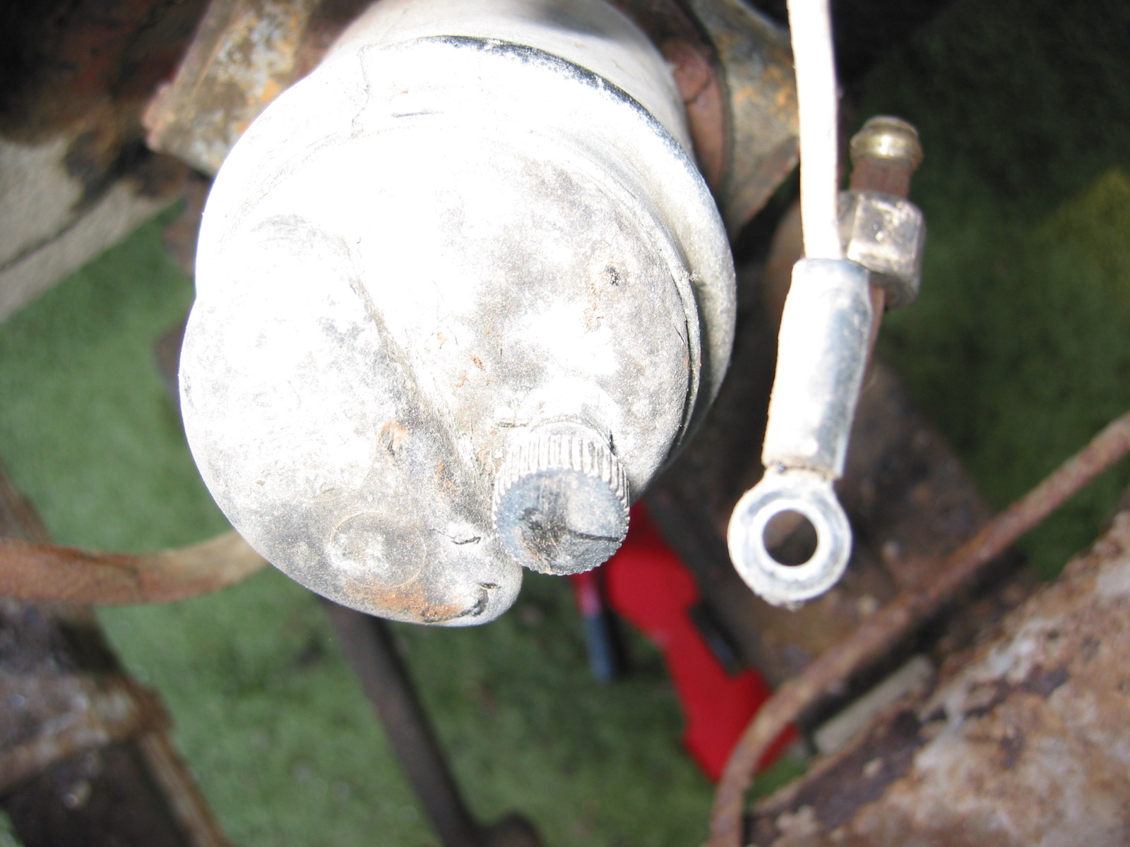
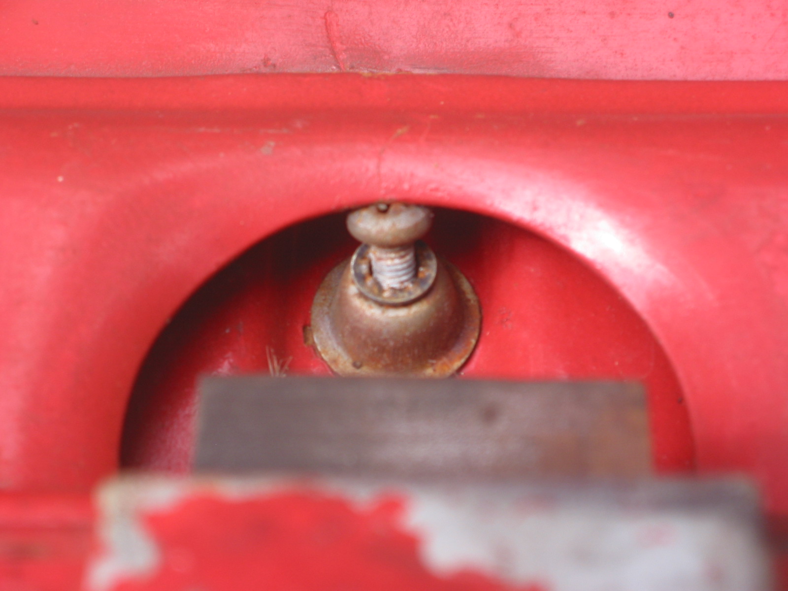
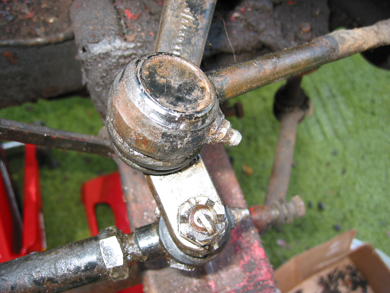
Steering Box Oil Filler Cap

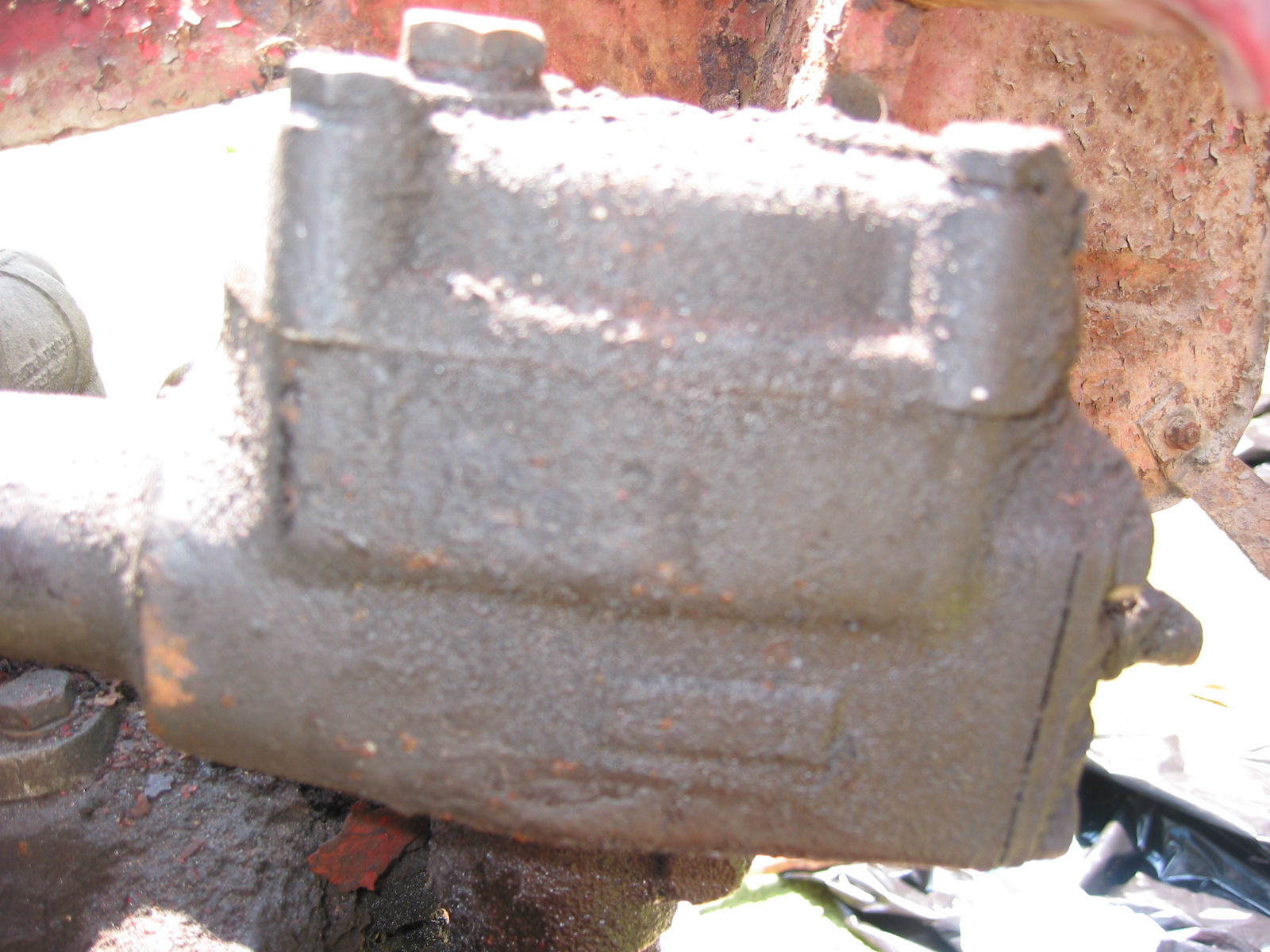
Steering Box Side View

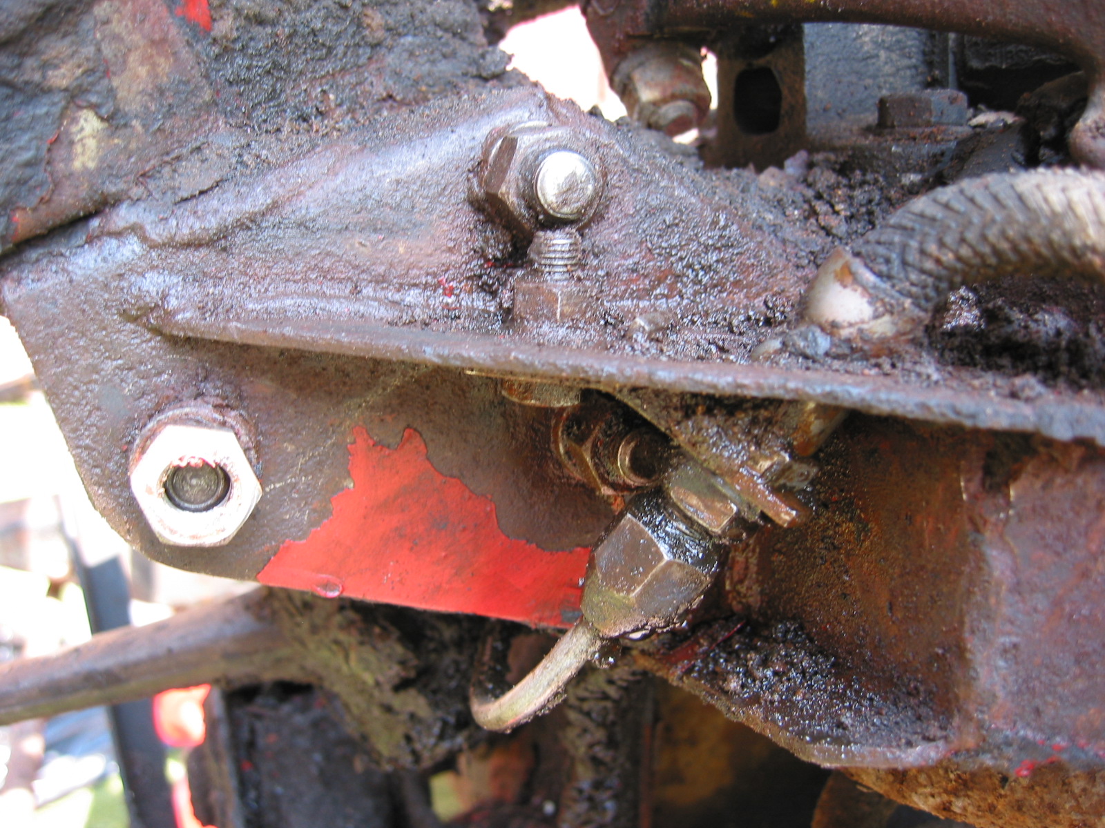
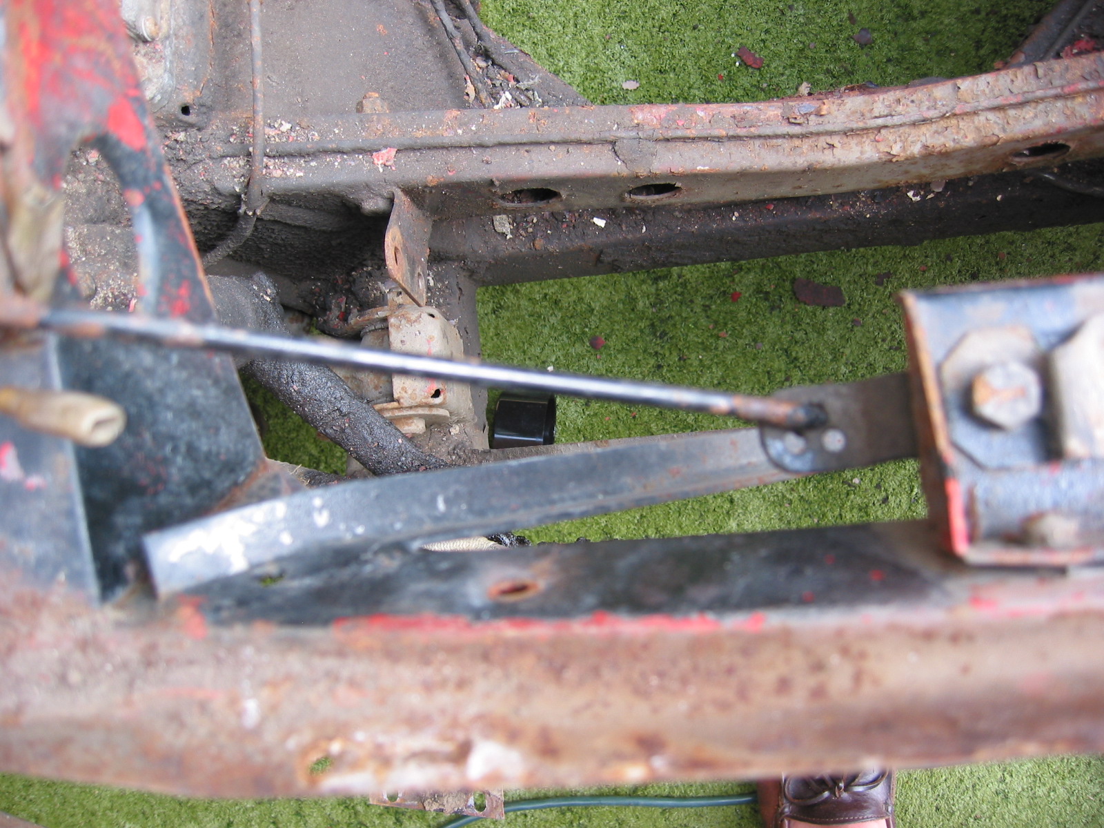
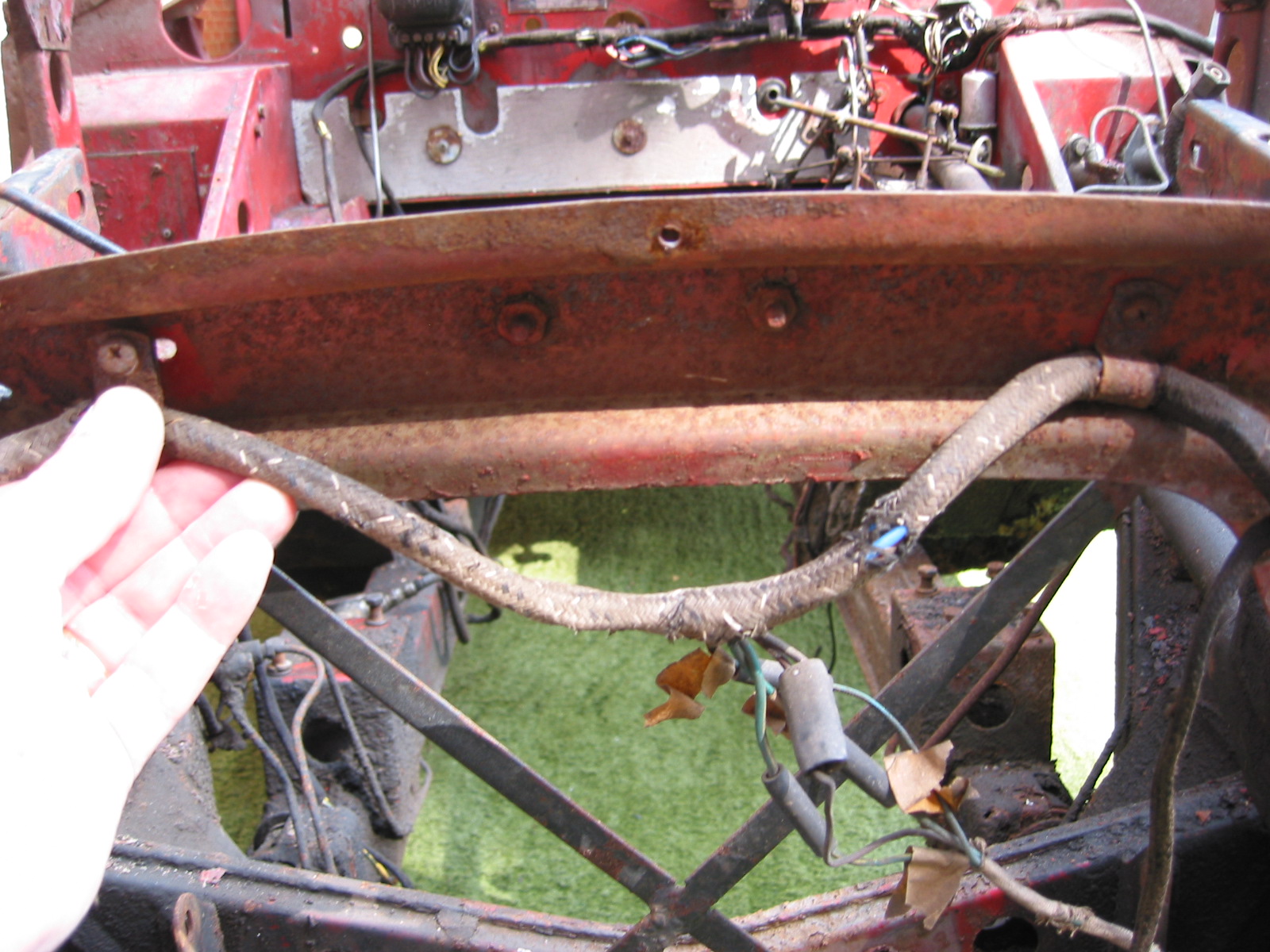
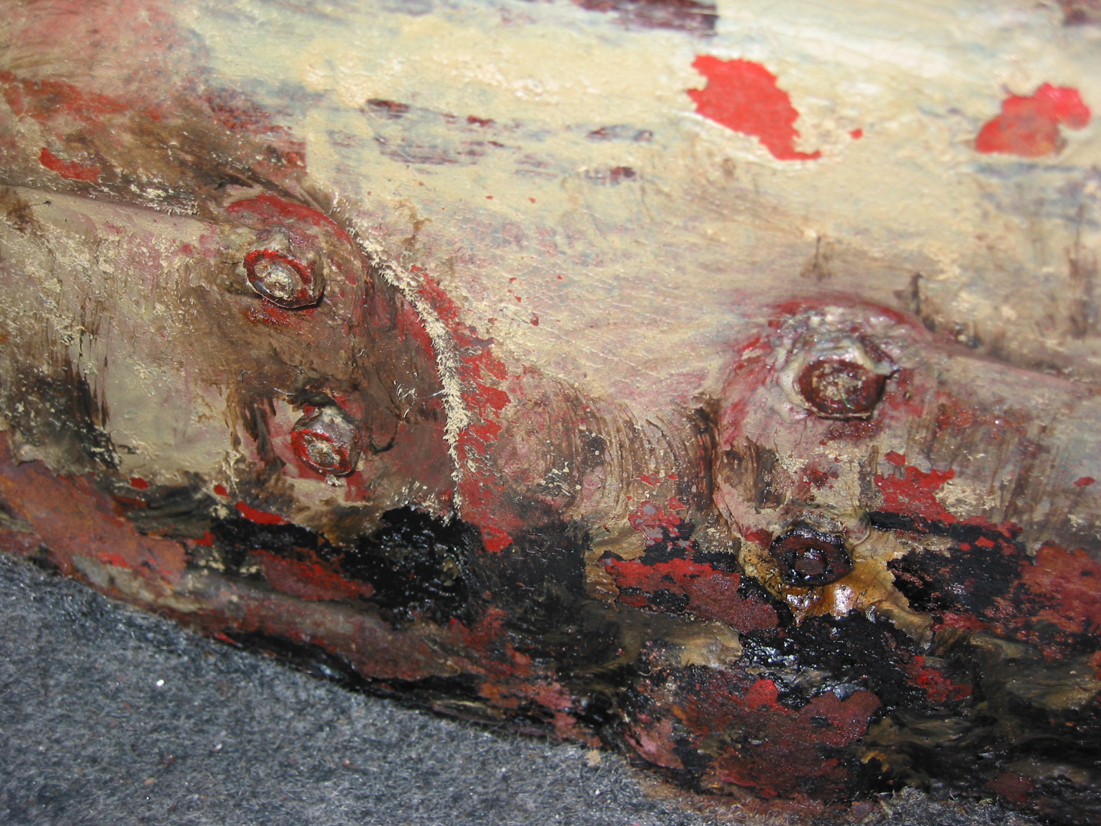
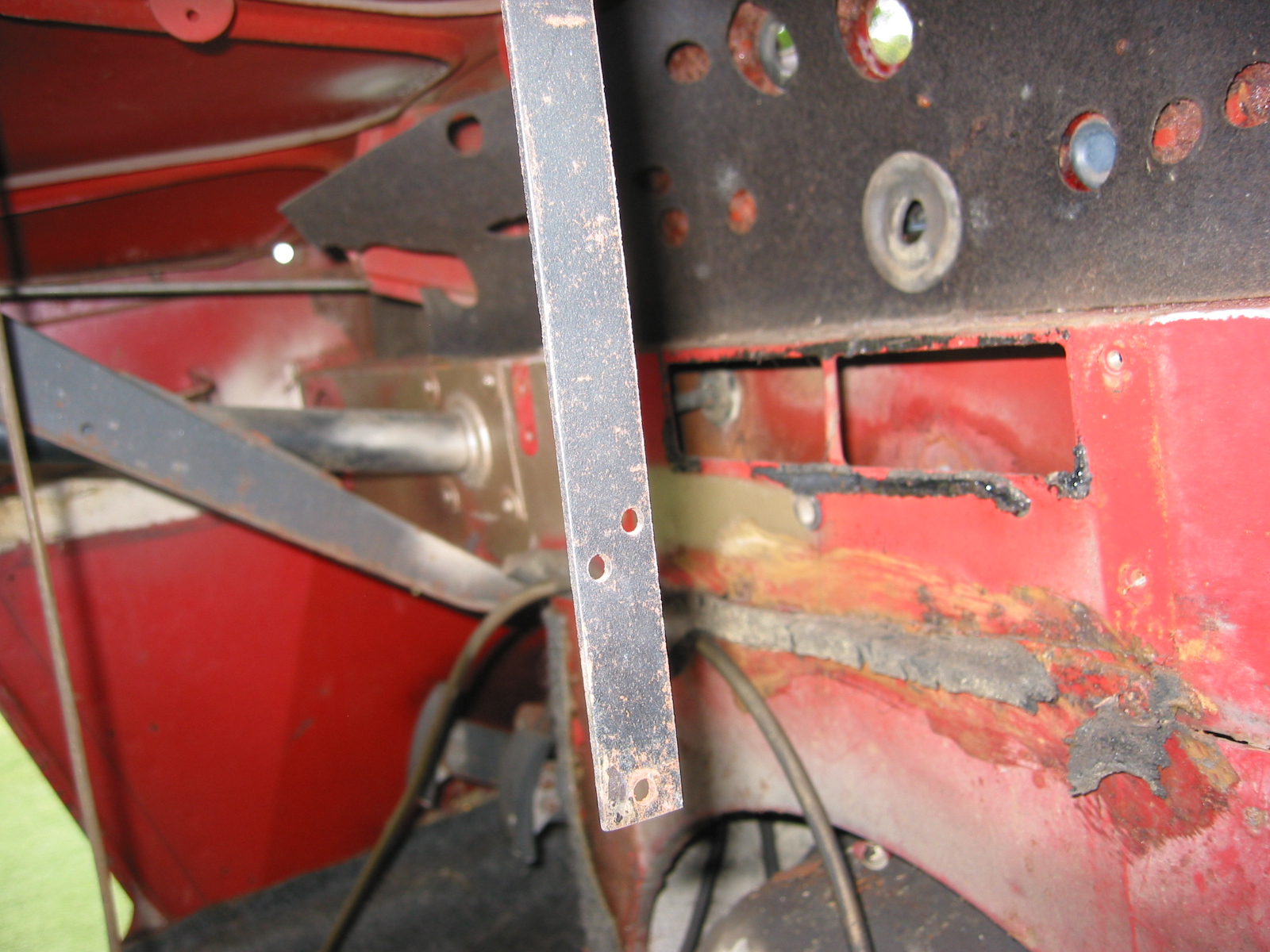
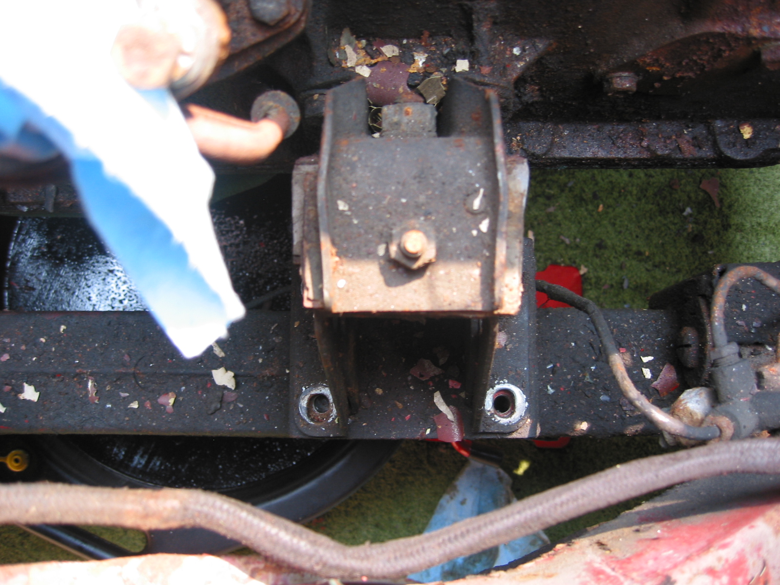
Steering Box Mounting Position

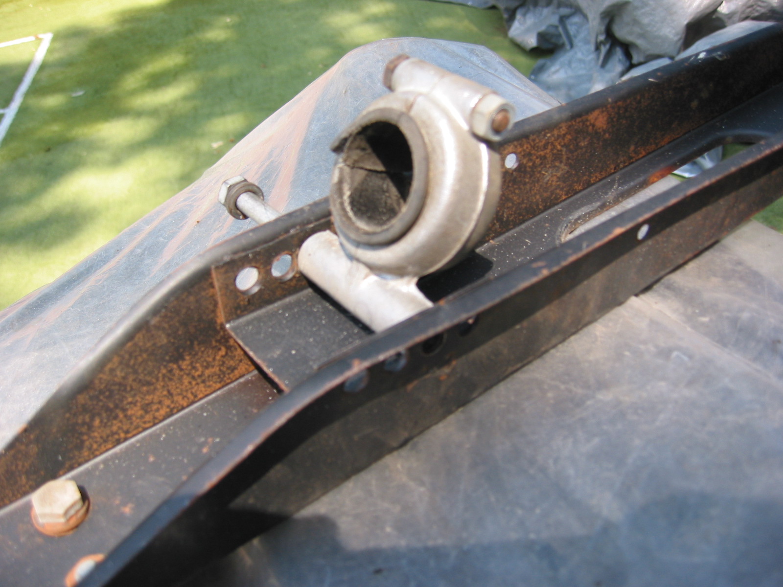
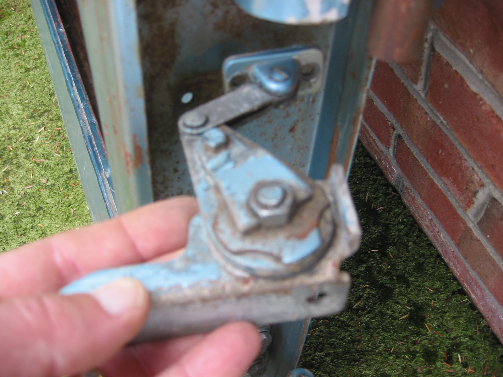
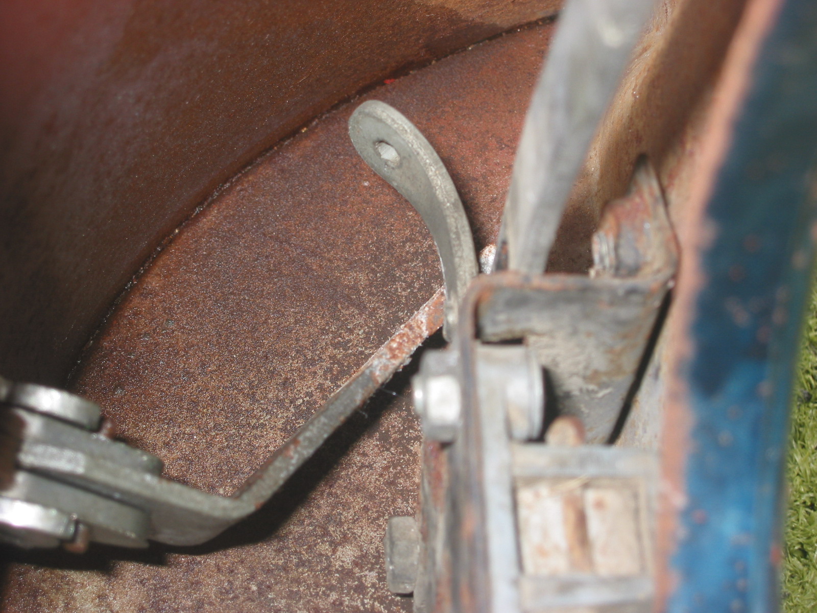
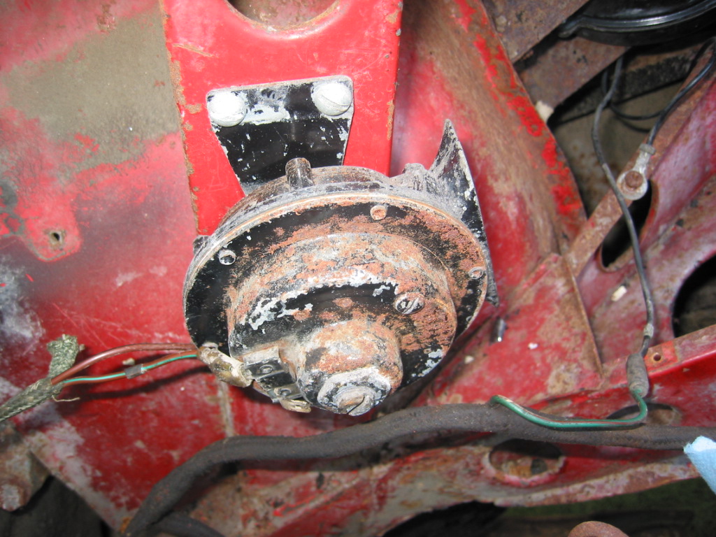
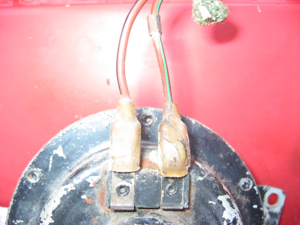
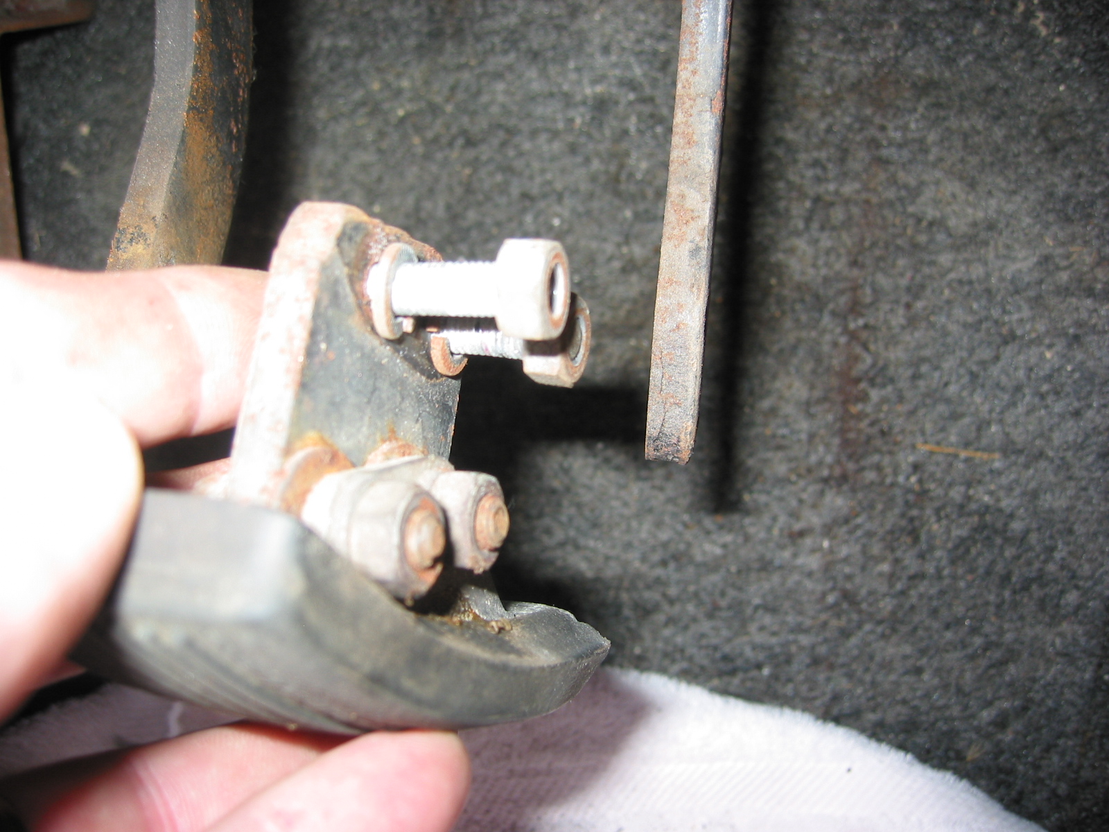
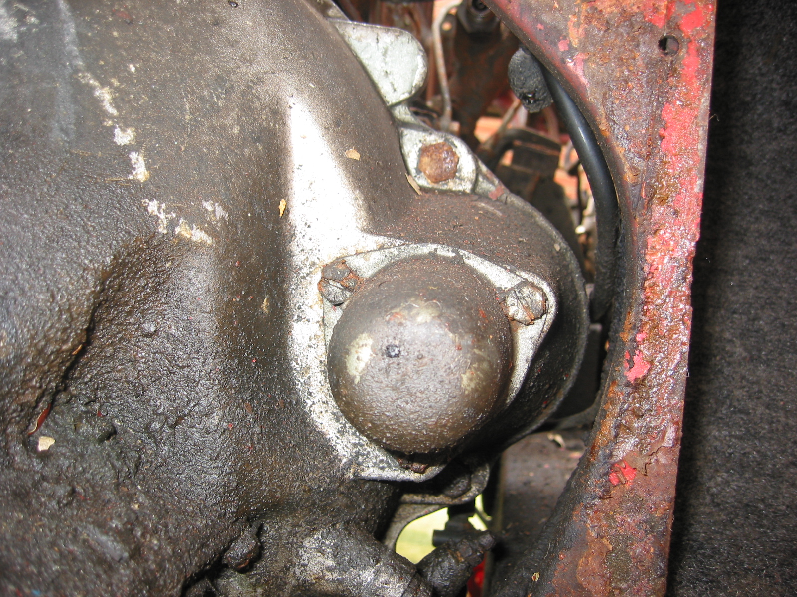
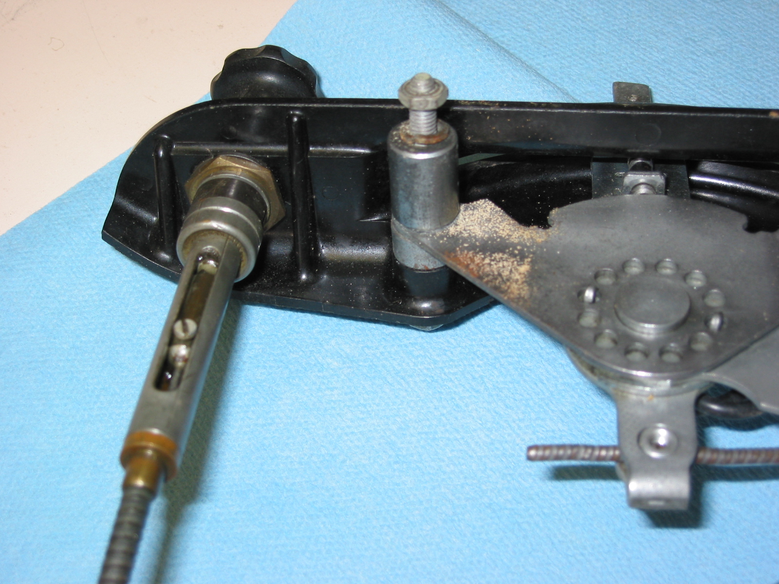
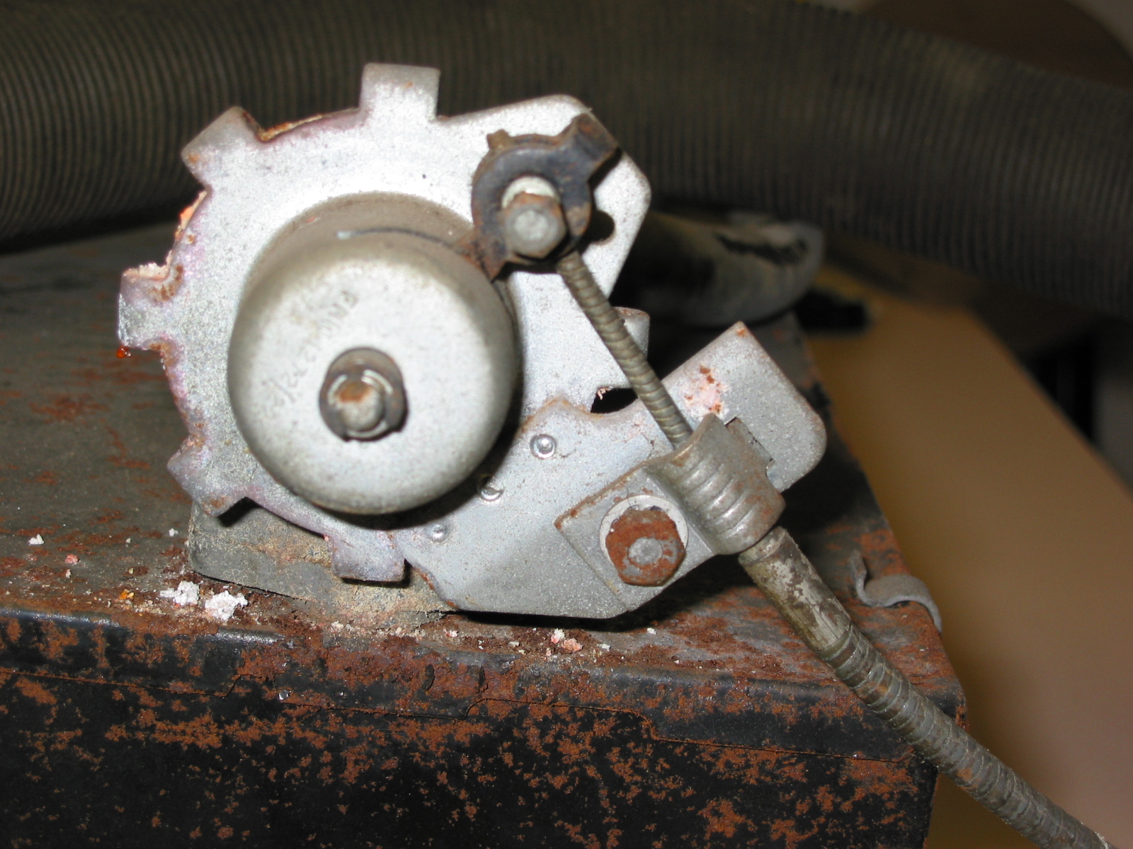
Steering Idler –  Unscrewed three bolts to the mounting bracket and lifted the idler away.

Steering Idler

Steering Idler 2

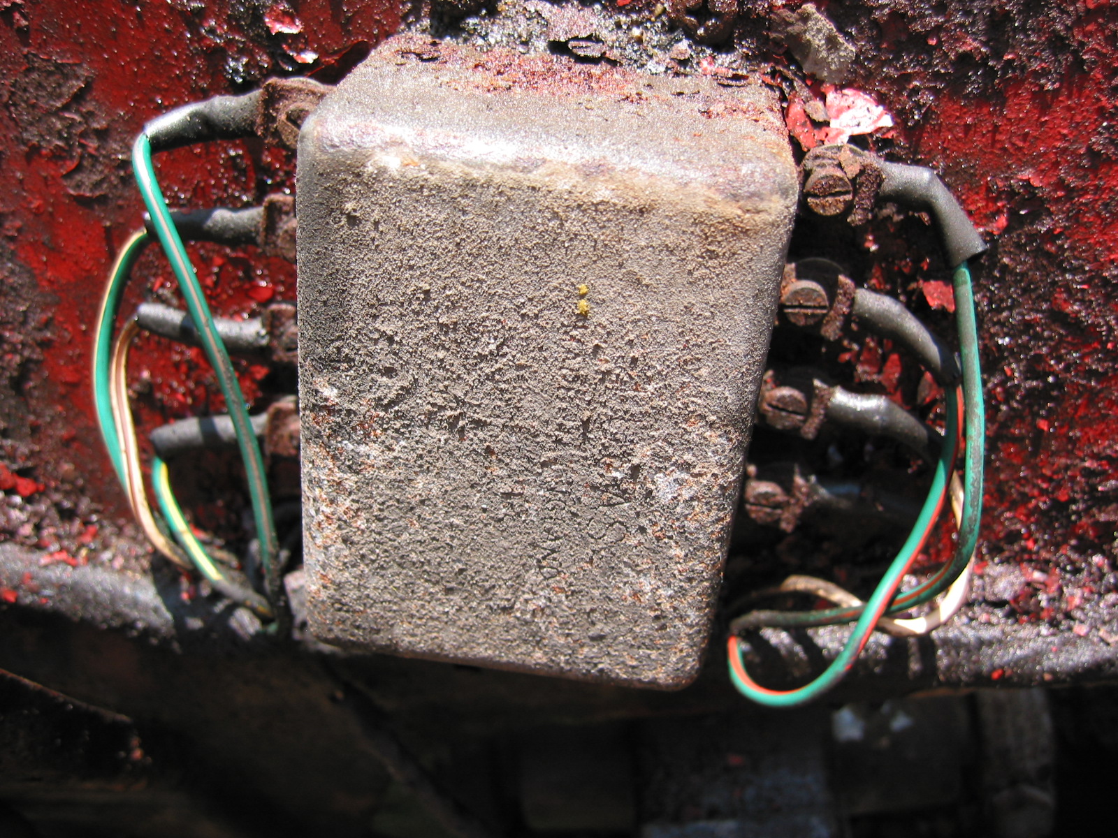
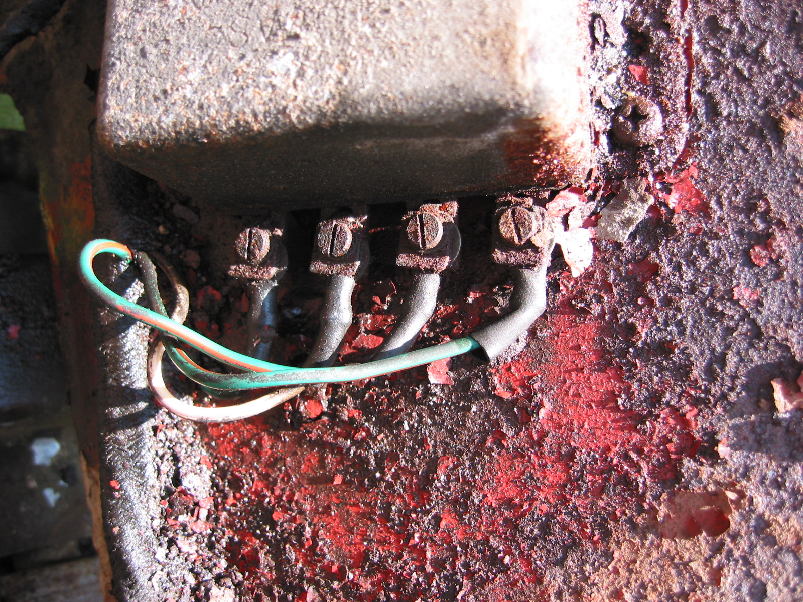
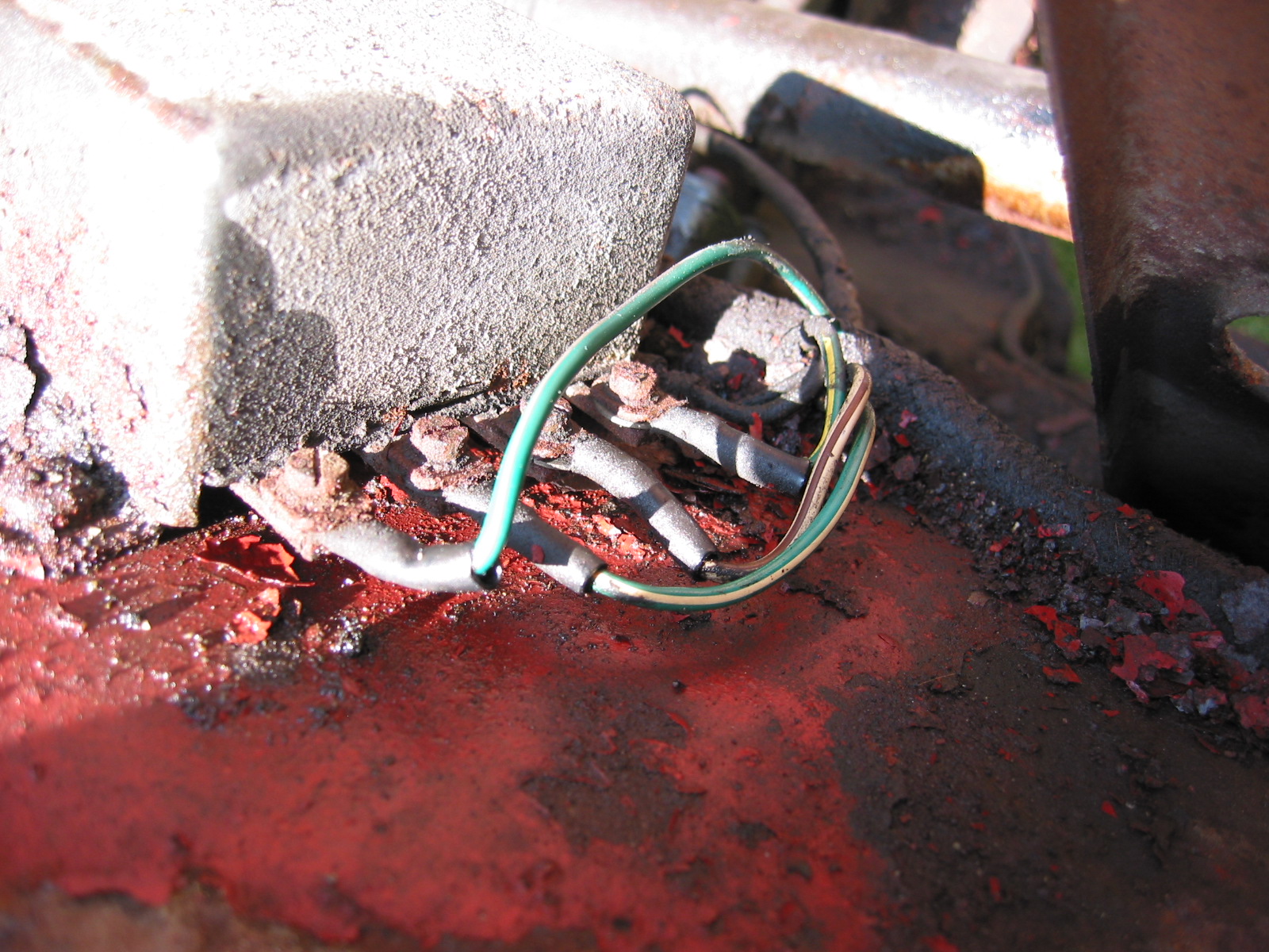
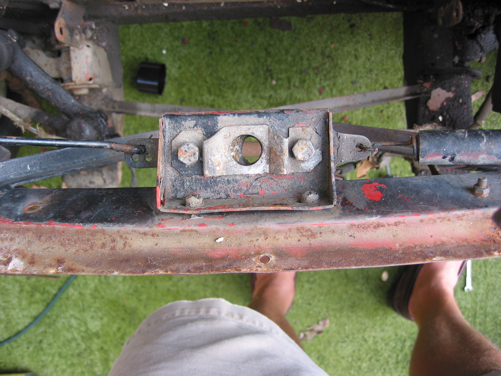
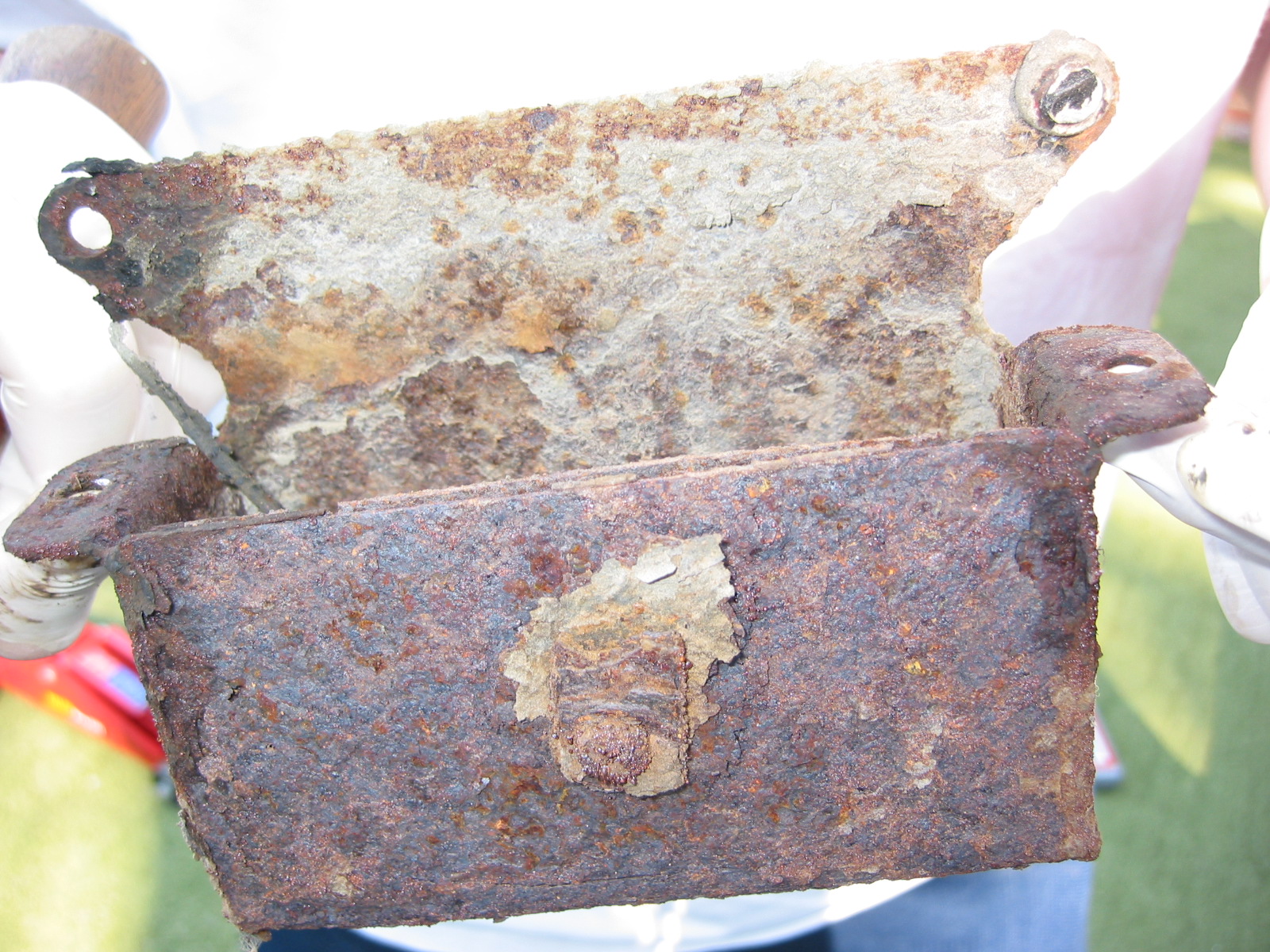
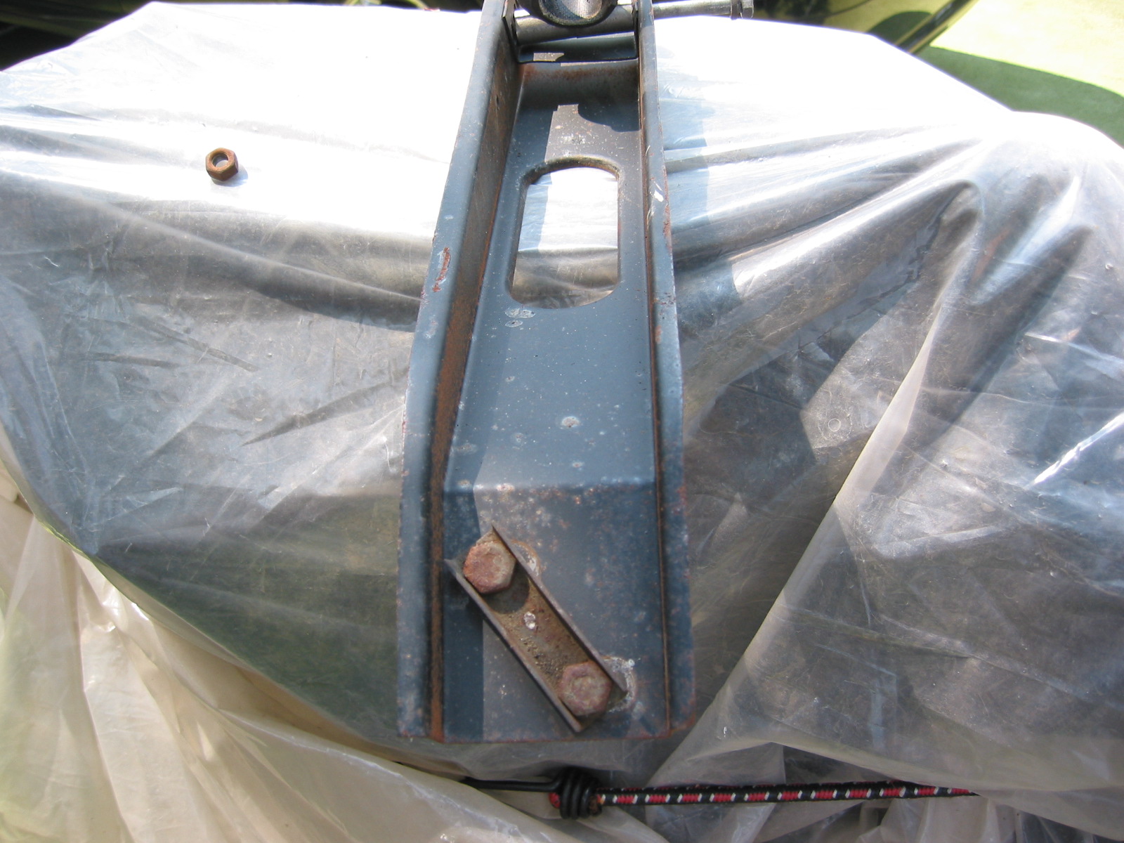
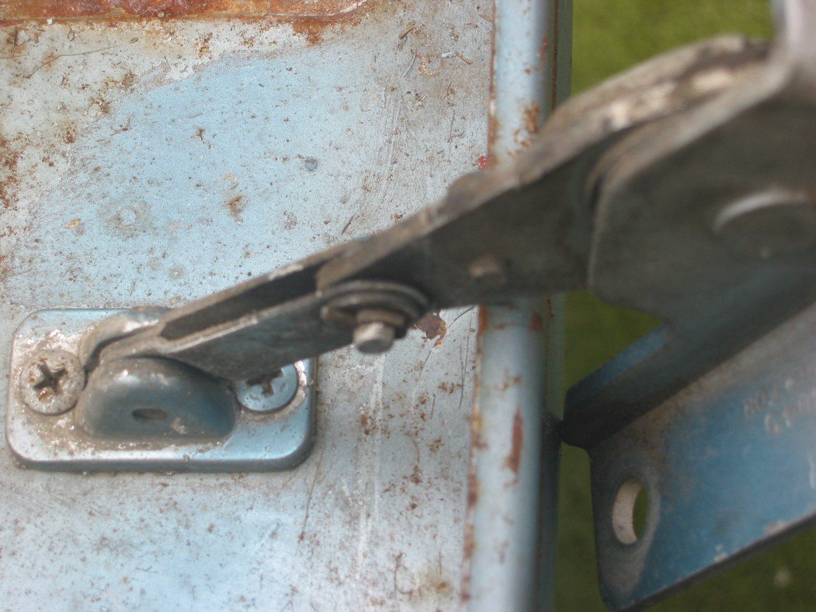
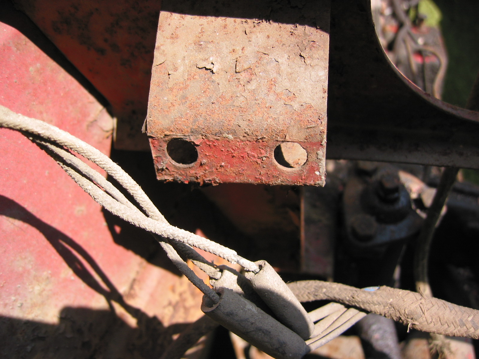
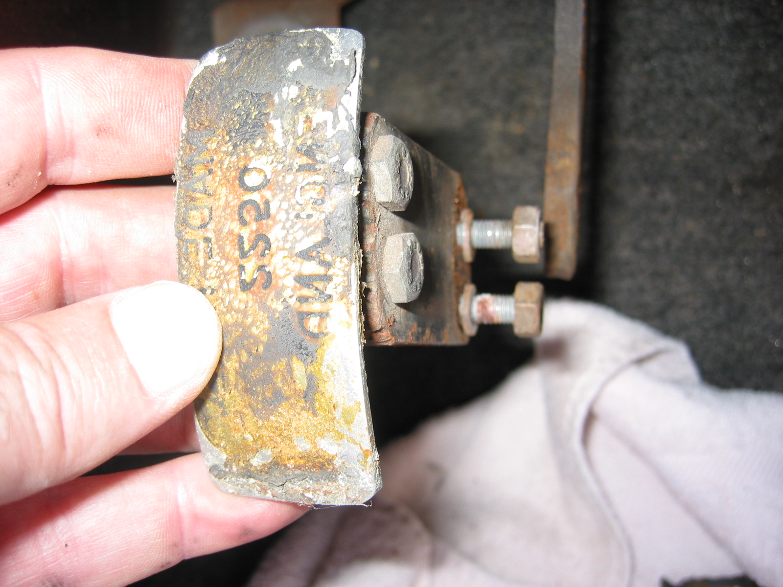
Aluminum Spacer Block Mount

Aluminum Bracket Spacers – for steering box and steering idler were removed. They appeared to be interchangeable.

Removing Aluminum Spacer Block

Aluminum Spacer Block

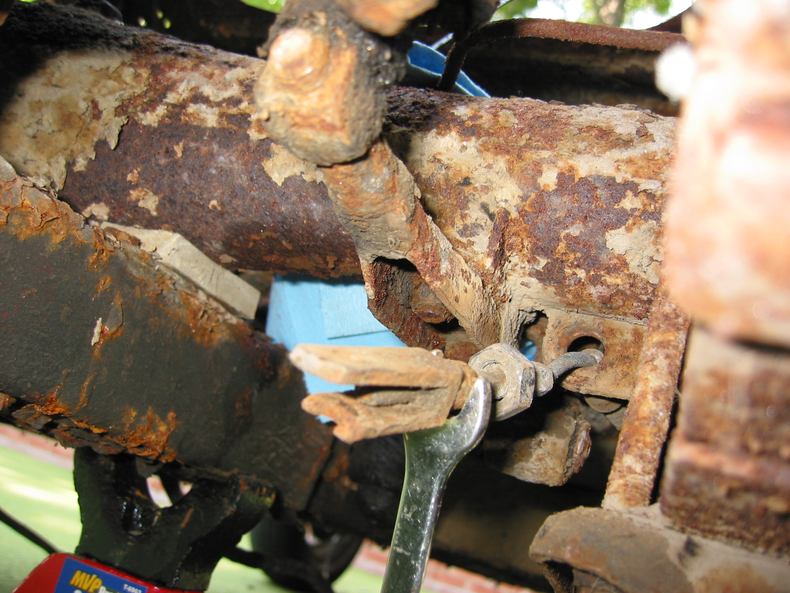
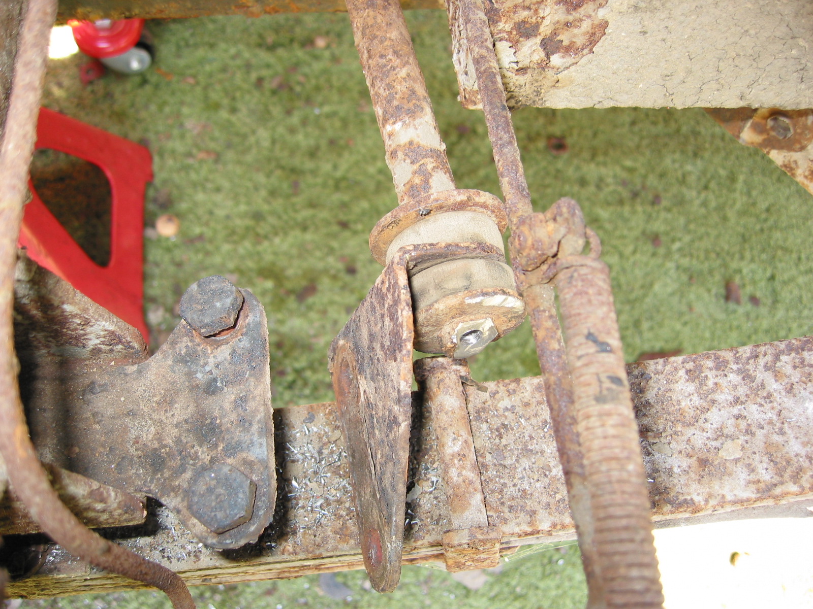
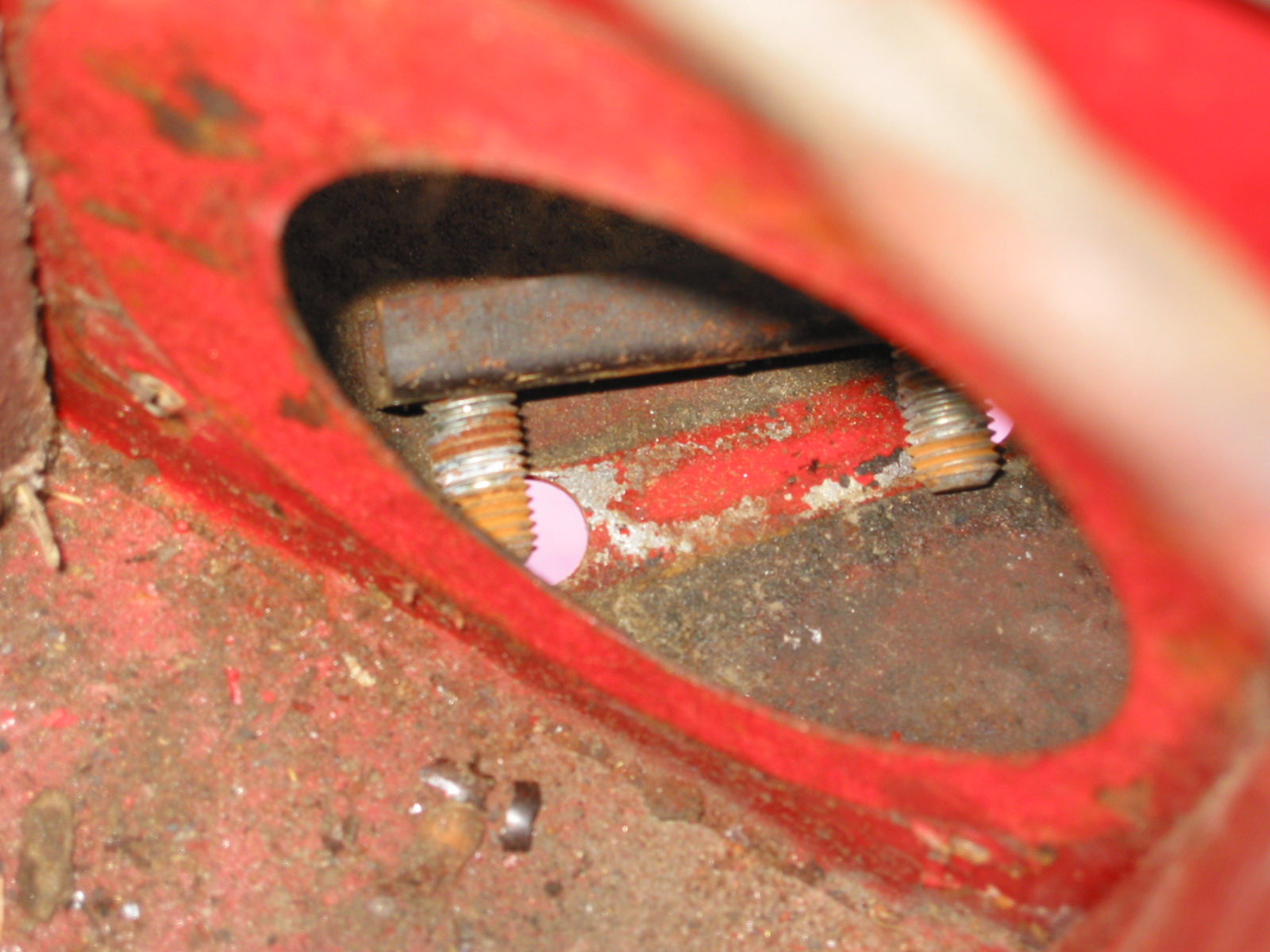
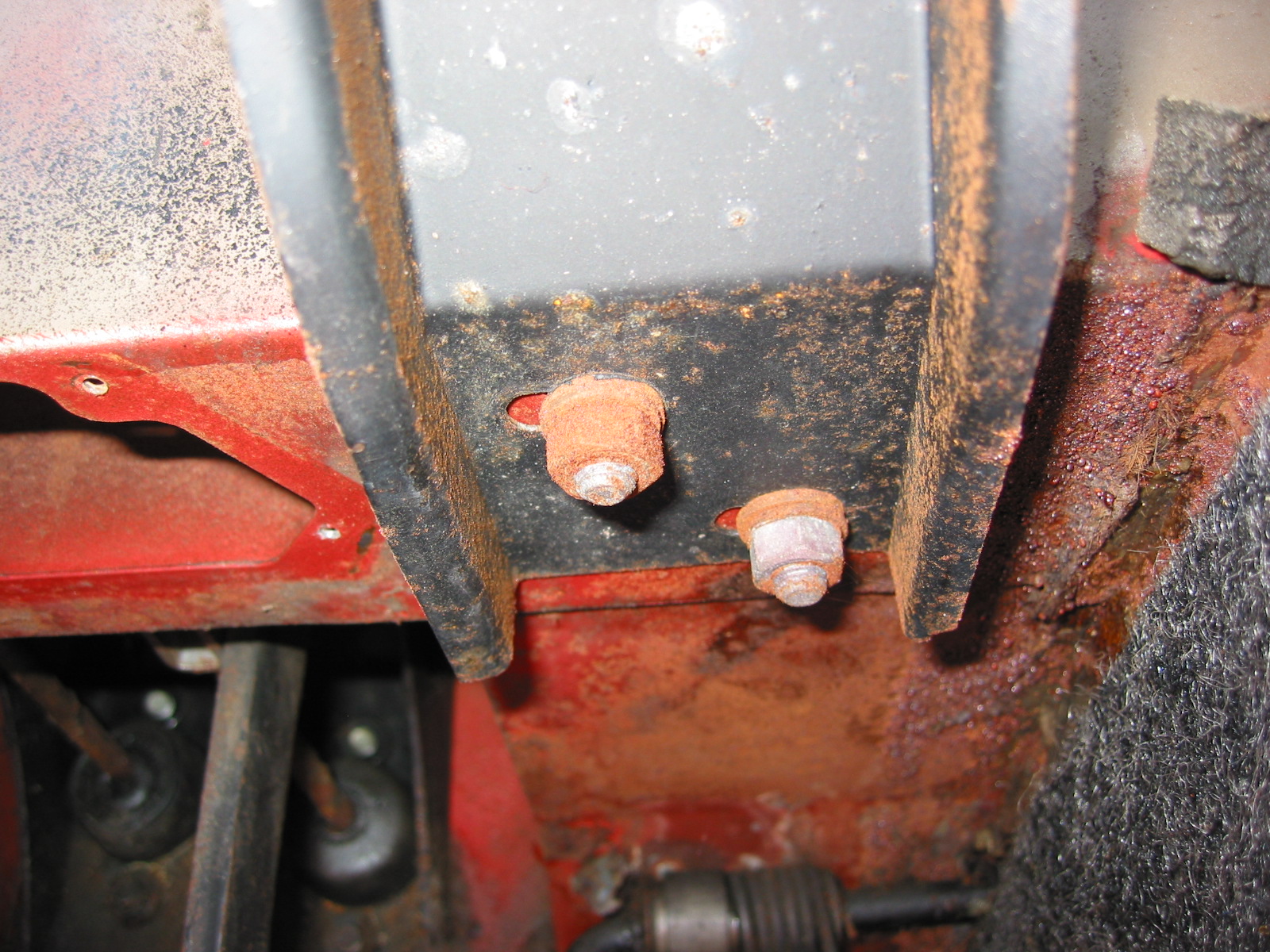
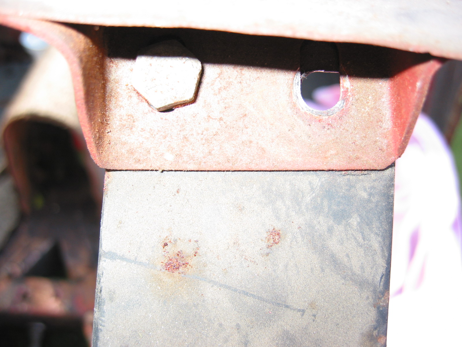
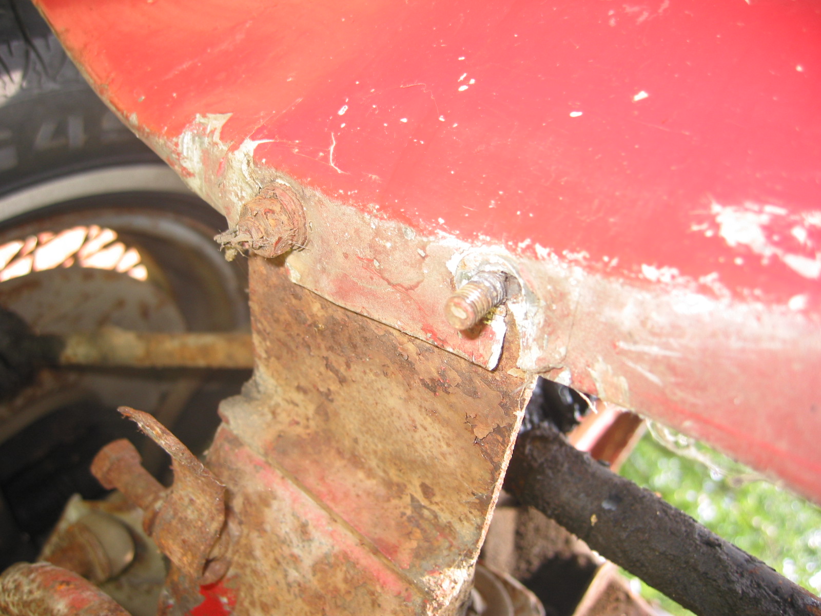
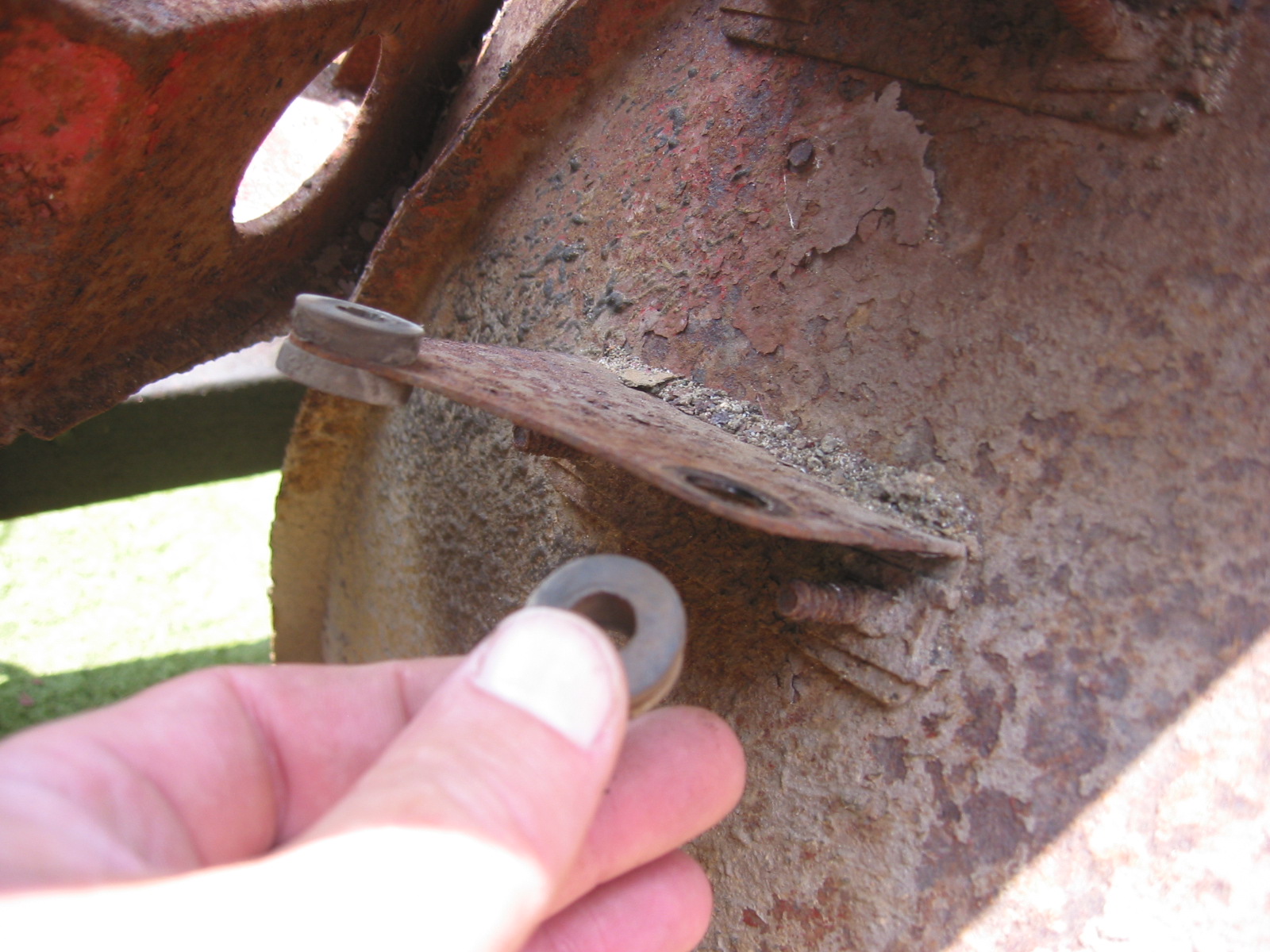
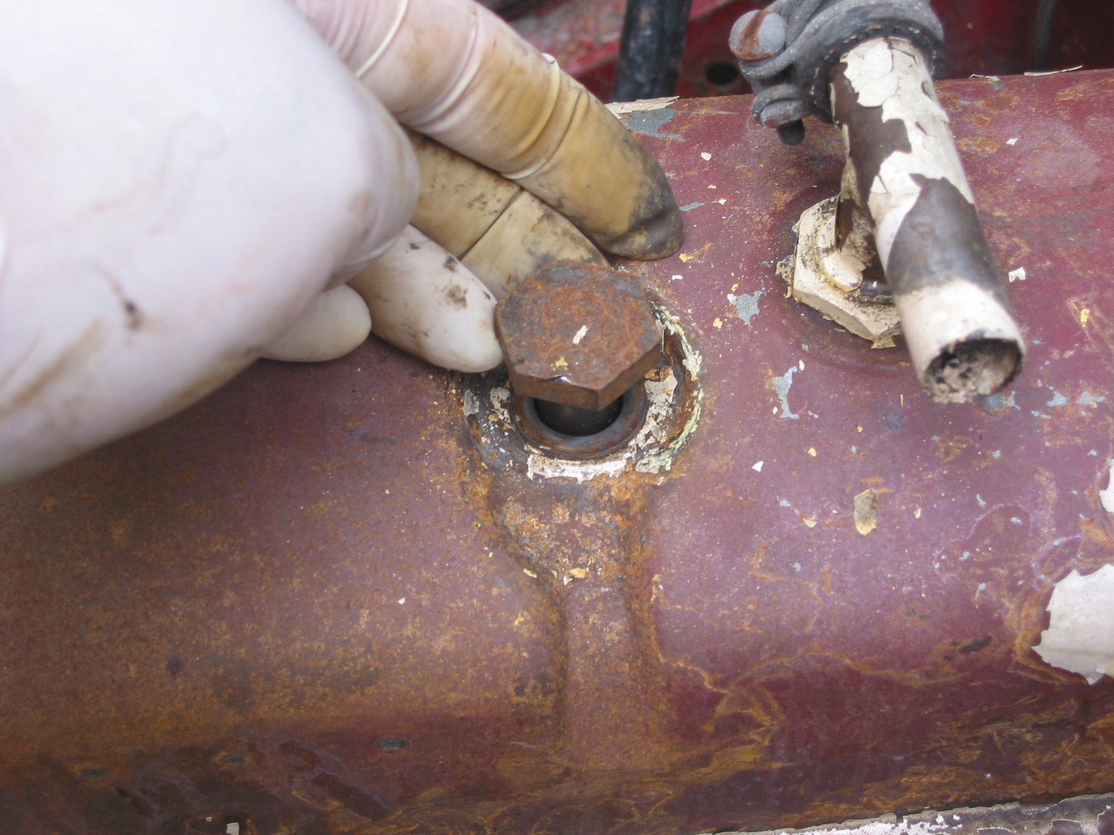
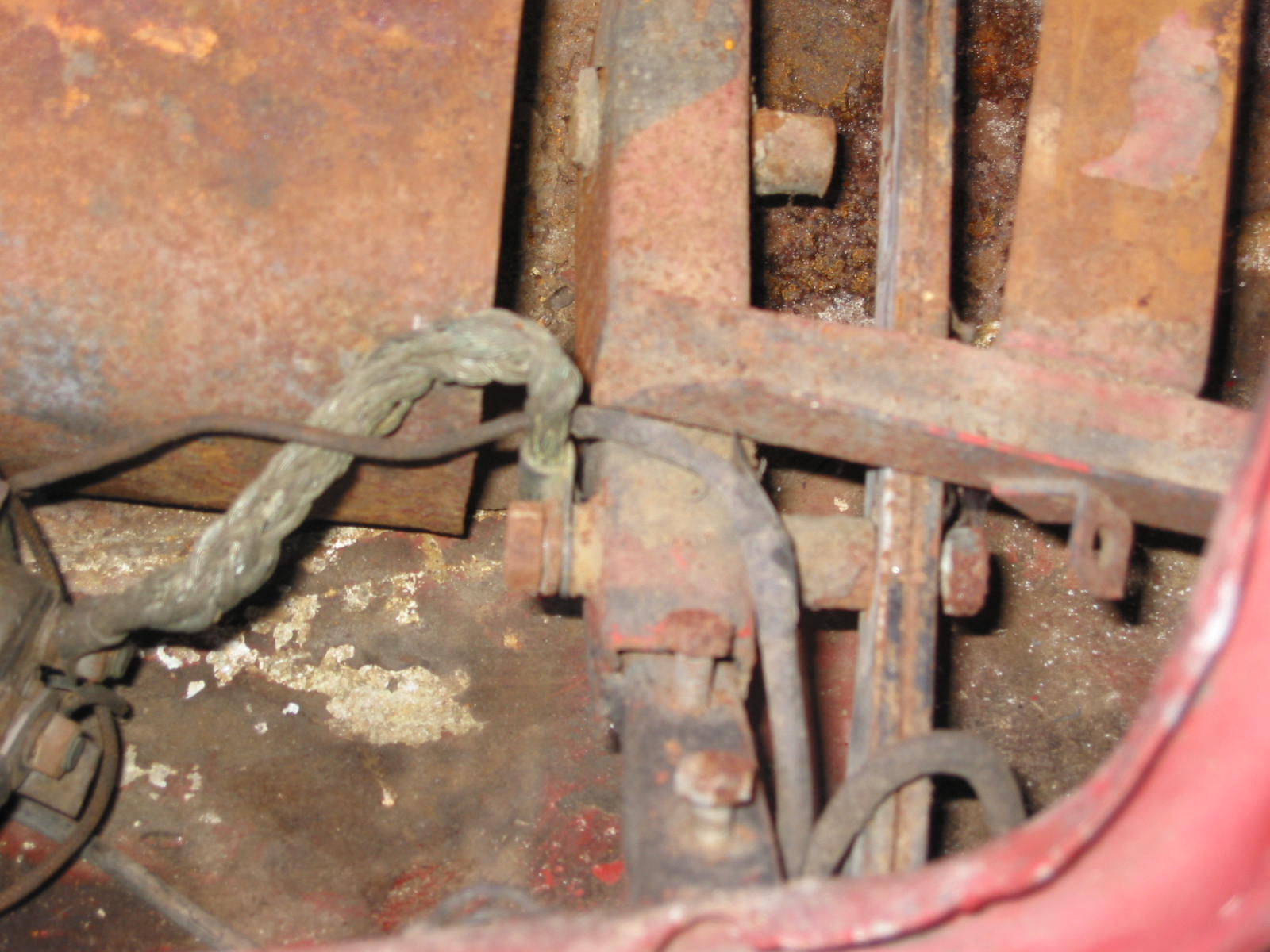
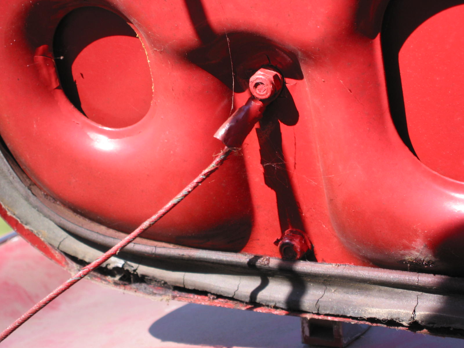
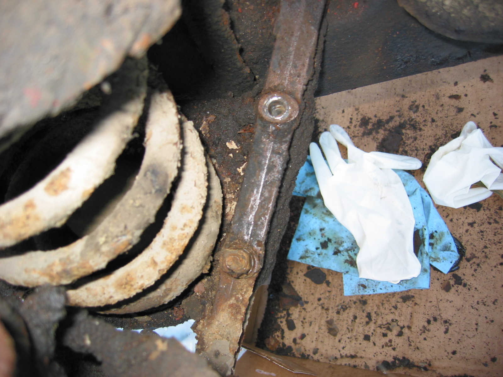
Front Suspension Coil Springs – Removed two bolts and nuts at a diagonal. Nuts on top and bolt heads under bottom spring bracket plate. (this is opposite the picture in the manual so we need to check other cars before reinstalling) Inserted two threaded rods with nuts into those holes. Then removed the other two mounting bolts and nuts. Finally, gradually relieved pressure on the threaded rods until spring tension was removed. The left spring was broken on the bottom coil.

Coil Spring and “A” Arm with spring pan removed

Spring Pan

Anti-Sway Bar Bracket
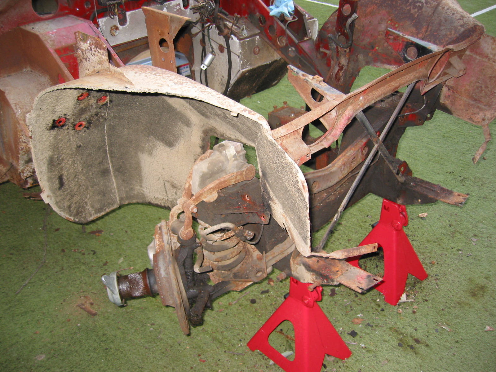
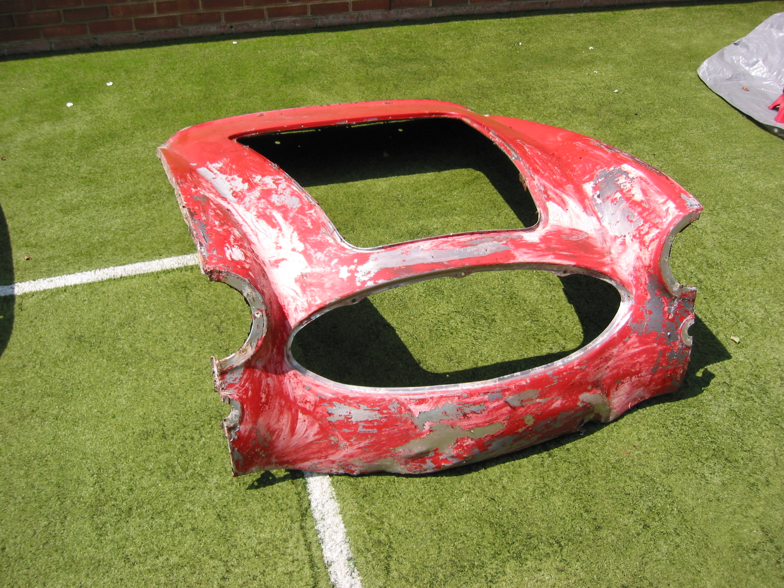
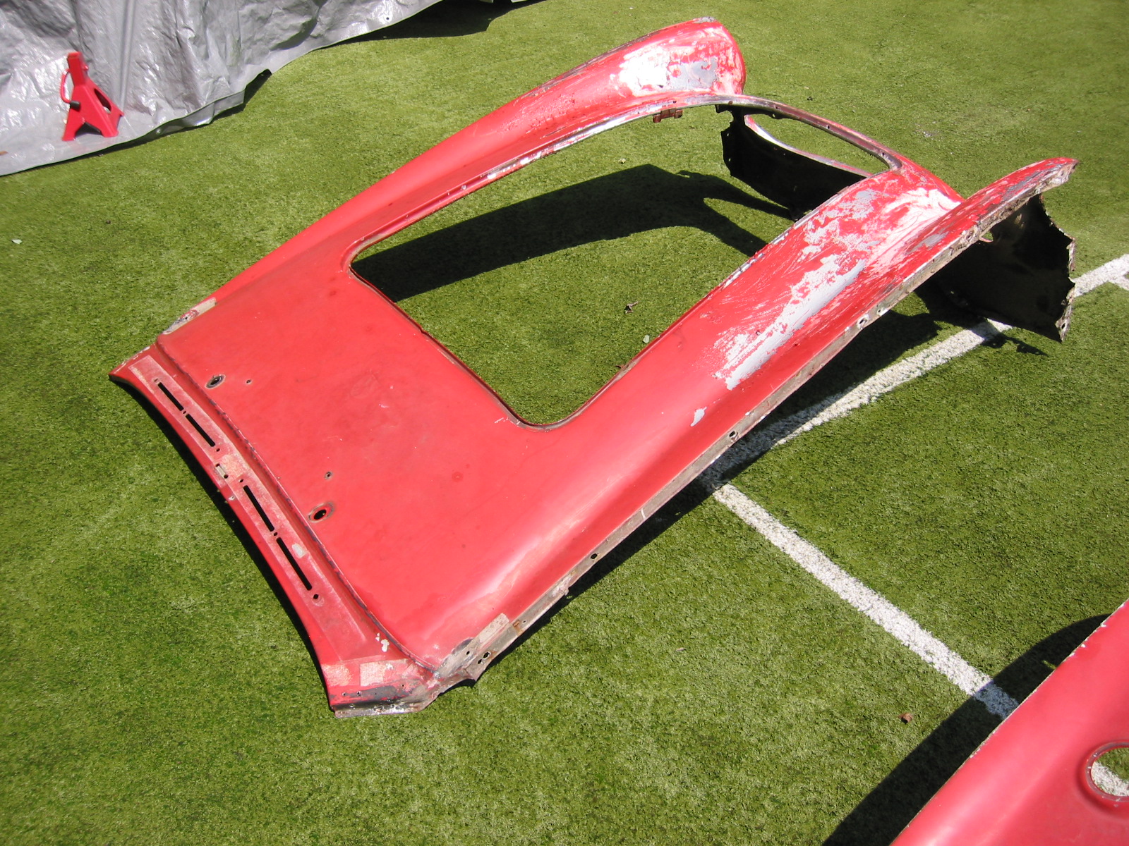
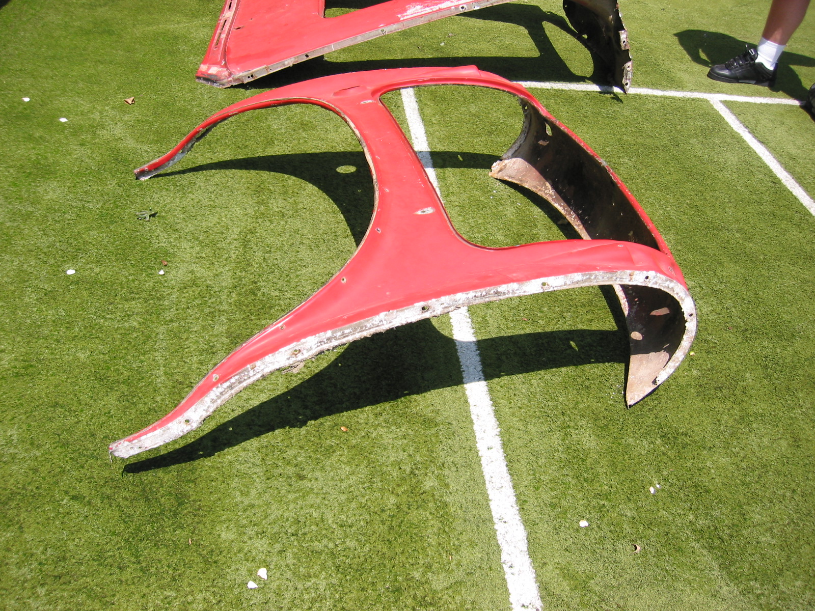
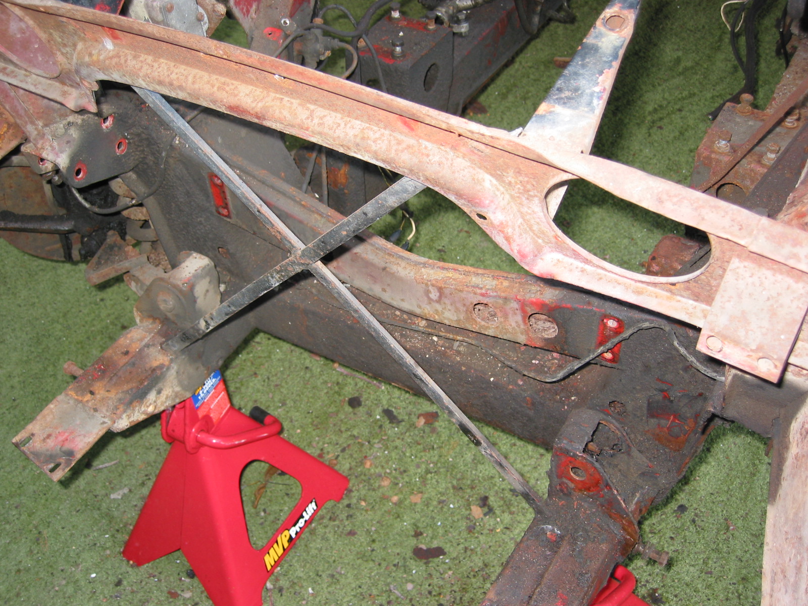
Tub on Stands

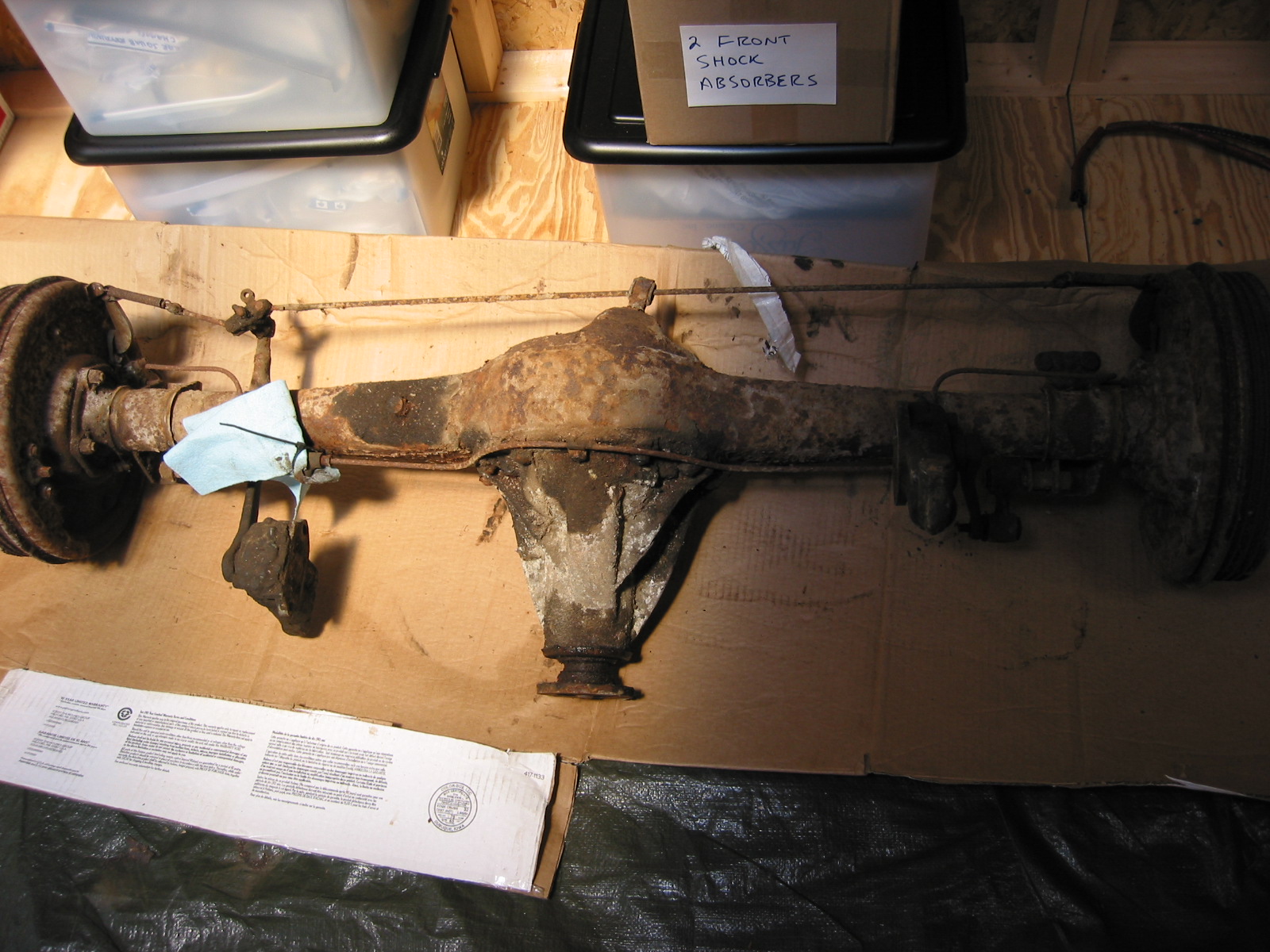
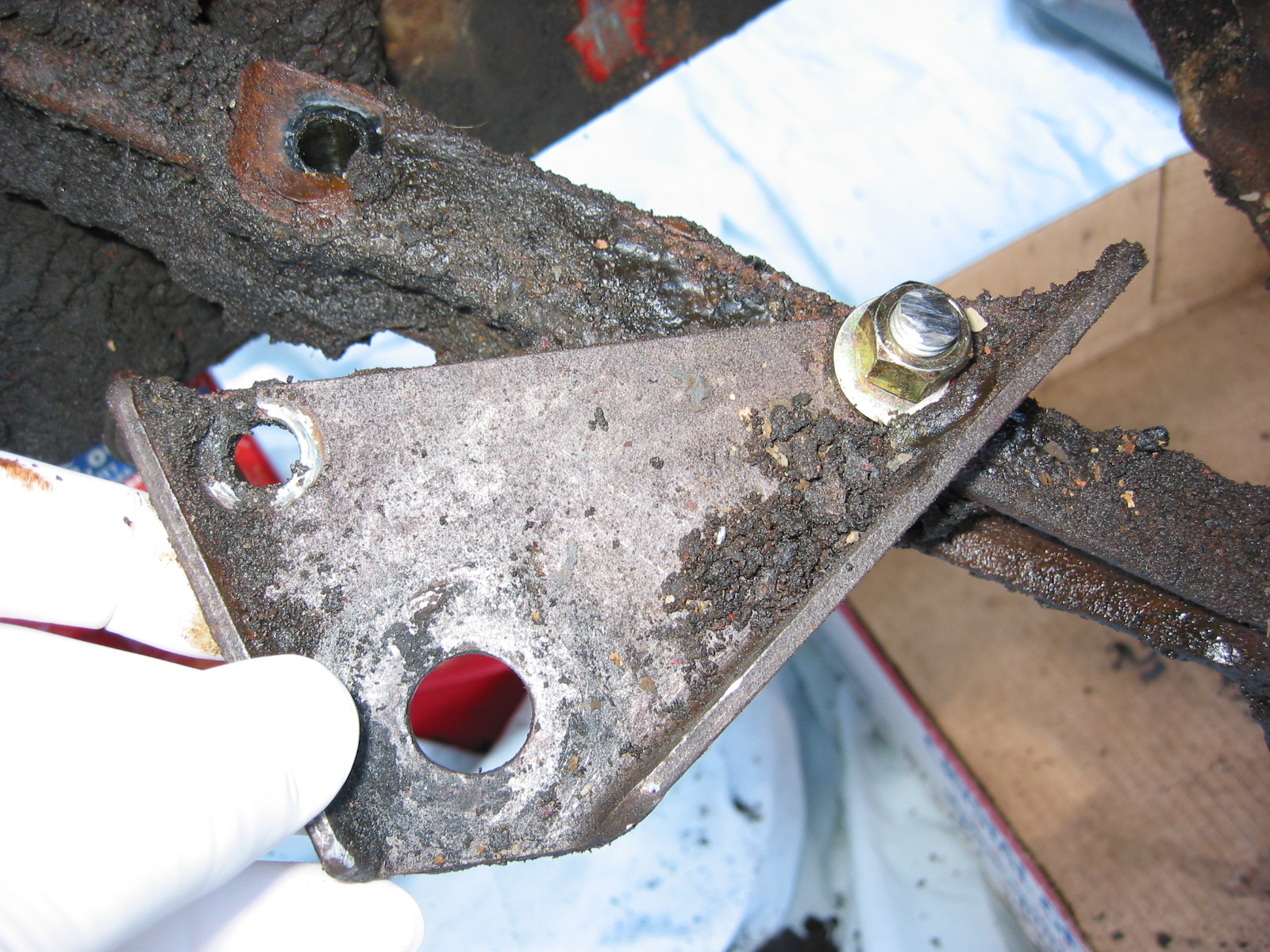
Front Suspension Arms, Brake Rotors and etc.  It was difficult to remove the arm bushings. They required extensive “torching” for heat and hammering, but all eventually released. Then removed the fulcrum pin securing the shock absorber arms and the four bolts to the shock towers on the frame. One hole on the right tower had been stripped and broken. Each shock had the remains of rubber rebound buffers on the towers. Once the shock was removed this permitted the removal of the left and right king pins and assembled units.
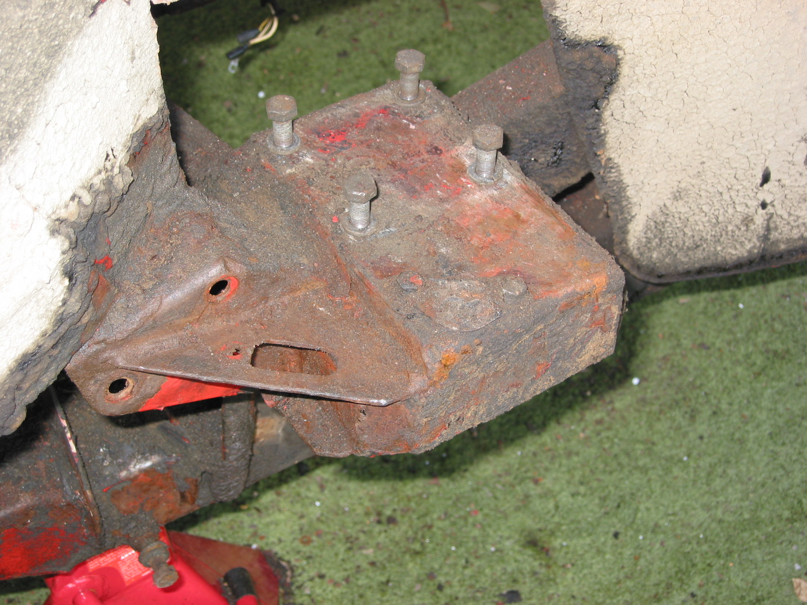
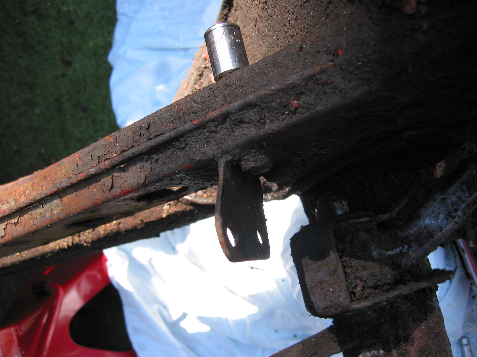
Front Shock Perch

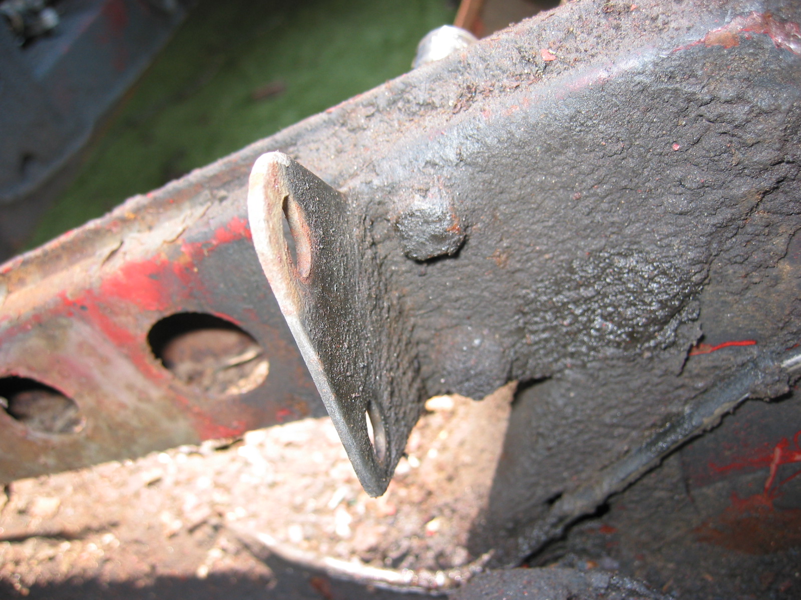
Bent “A” Arm Bracket
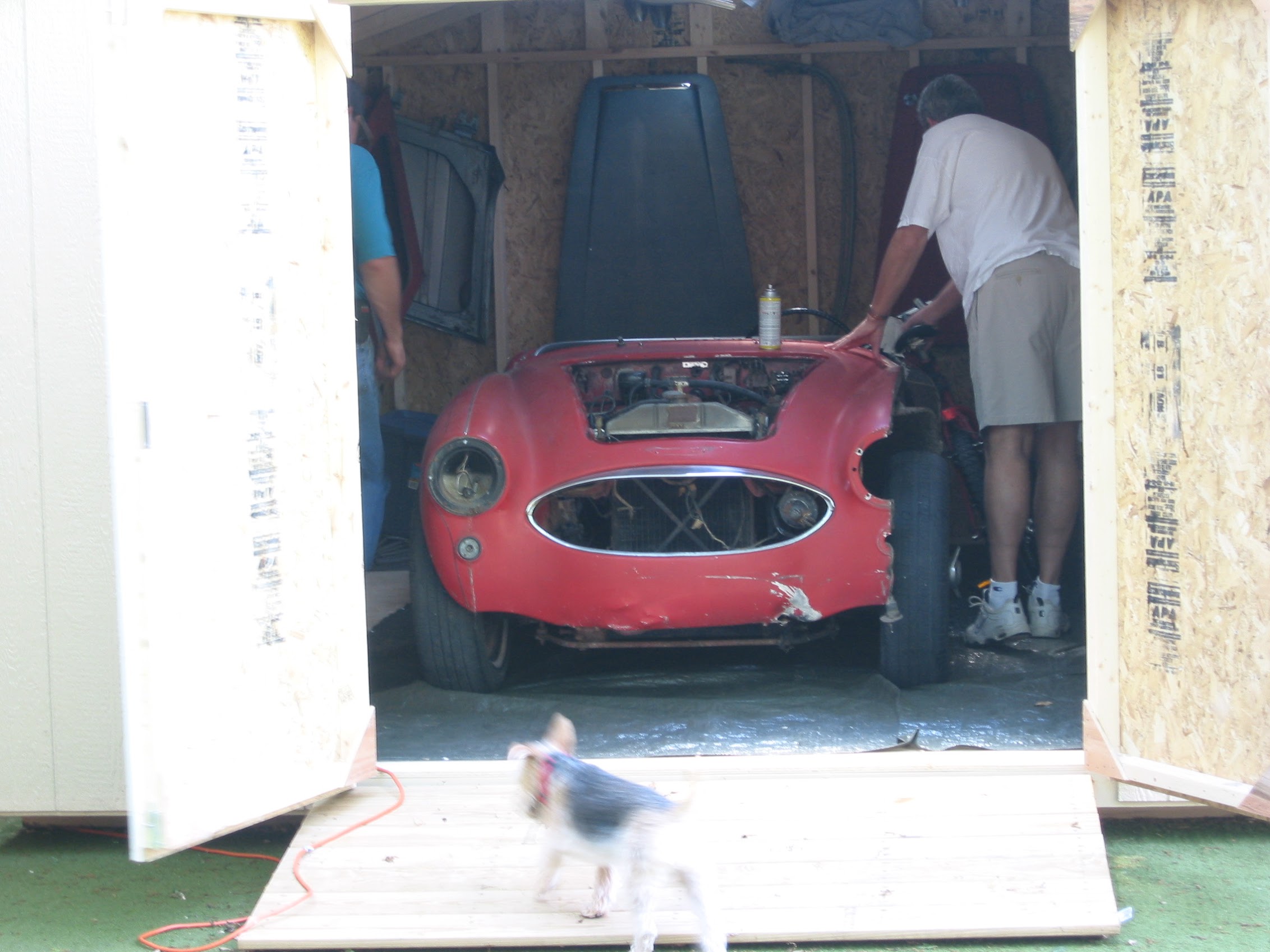
Radiator 

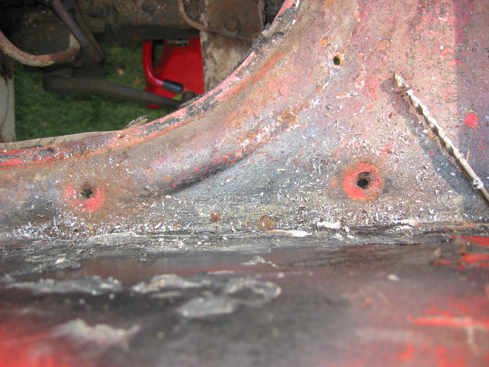
Radiator Brackets were removed from the frame. Two 1/2” bolts for each bracket. We will be replacing the original radiator with an aluminum unit from Cape International.

Radiator Lower Mount

Radiator Mount Bracket

Radiator Brackets Removed


Chapter 8 – Disassembly

Fresh Air Intake Assembly –  Three screws, two with nuts and one welded onto the tube secure the assembly to the superstructure. Disconnected the air control cable.

Fresh Air Intake Assembly

Fresh Air Intake Assembly

Flasher Relay –  Two cross head screws on top, one on bottom. All have nuts welded on the outside of the wheel well. The bottom screw also holds a wiring harness clamp and the ground wire. Starting from top left and going down – first wire is green with pink stripe, second is green/white stripe, third is white/brown stripe, and fourth is green/yellow stripe. Starting from the right top and going down – first wire is green/brown stripe, second is green/red stripe, third is white/purple stripe and fourth is green/? Stripe. Black ground wire is at bottom.

Flasher Relay Wiring 1

Flasher Relay Wiring 2

Flasher Relay Wiring 3

Bonnet Latch Support Bracket, Lever and Spring –  Note that the left side of center has a rubber tube over the spring and extension rod.

Bonnet Latch Return Spring

Bonnet Latch Rod

Bonnet Latch Support Bracket – The bracket is secured by two bolts and nuts.

Bonnet Latch Support Bracket

Bonnet Latch Return

Wiring harness extension for lights and horns – Two clamps located by screws and nuts at the front of the car.

Wiring Harness Clip Screws

Wiring Harness at Front of Car

August 3, 2002

Rear Axle and Related Assembly

The Bump Stop Boxes –  were removed from both sides of the car. Two large pozi-drive screws with large washers and nuts located by the rear occasional seats hold the boxes. Two bolts and nuts must also be removed in the side of each box that secure clamps for wiring. In our case the bolts were all broken from wear and tear.

Rear Axle Bump Stop on Car

Rear Axle Bump Stop Removed

Mounting Holes

The Fuel Pump   was removed to get it out of the way of the axle. Disconnected 5/8” in and out fuel pipes to the pump. Remove 4 7/16” bolts into fixed nuts on the rear bulkhead wall. Finally, disconnected wire at knurled fixing knob.

Fuel Pump Mounted to Bracket at Rear Kick Panel

Disconnected White Wire to Fuel Pump

Fuel Pump and Bracket Removed

Boot wiring harness extension –  Wiring goes to the fuel sender and lights. We clipped the wire at the bulkhead for easy removal since we knew we would be replacing it. Two clamps with split head screws secure the wiring through the bulkhead wall. Additional connections are then made to route to the tailights.

Fuel Pipe to Pump and Wiring Harness

Wiiring Harness to Boot

Wiring Connector for Lights in Boot

Wiring Clip

Wiring and Handbrake Cable

Wiring Cable Removal

Handbrake cable –  The cable was removed from its axle attachment. To save time we just cut the flexible brake line hose to the junction.

Handbrake Components

Handbrake Components at Rear Axle

Rear Shock Absorbers – First removed nut to axle link. Then removed two nuts and bolts to rear bulkhead for each.

Rear Axle –  Drain differential fluid from the rear end. Place jack under differential to take pressure off springs. Loosen the four nuts on the U bolts under the mounting bracket. The nuts should be loosened gradually to avoid too much pressure on the spring. Disconnect tramp bar at mounting bracket on axle. Rotate axle and lift and slide out to the right.

Rear Axle U Bolts

Rear Axle U Bolt Mounting Plates

Panhard Rod Mounting

Rear Axle Removed

August 4, 2002

Steering Assembly

Steering Column Support Clamp – There are four holes available for the bolt and nut on the steering column bracket. The bolt was found in the 2nd hole from the firewall. Bolt heads were to the right, nut to the left.

Steering Column Mount

Steering Column Bracket Mount

Steering column bracket –  Removed the bracket by loosening four bolts and nuts.

Steering Column Bracket Removed

Steering Column Rubber gasket

Steering Shaft Bracket to Frame Mount from below

Steering Shaft Bracket to Frame Mount from Above


Chapter 7 – Disassembly

Front Shroud

Removed five cross head drive screws at the rear of the bonnet. Three screws with nuts must be removed at the front of the shroud at the bonnet opening. Two cross head screws and nuts also attach the shroud to upright posts. A third bolt and nut holds the prop rod bracket. Five pop rivets were drilled out along the scuttle. Two additional rivets must be drilled out along each side and where the rubber seal attaches to the scuttle. Two bolts securing the shroud to each frame extension in the front must be loosened from their nuts. The shroud can then be released from the rear and pulled forward.

Prop Rod Bracket Removed

Rivet Removal

Front Shroud to Frame Mount

Shroud Removed 1

Shroud Removed 2

Rear Body Panel (shroud)

The rear body panel is released by first drilling out 19 rivets along the lower lip. Thirteen rivets must be drilled out that hold the body panel to the luggage compartment frame. Two or three rivets must be drilled out on the side of the rear body panel where the wing fastens to it. Four cross head screws and nuts must be removed from the top lip of the boot opening. The rear body panel can then be removed. Care must be taken to not bend the small front lip on the aluminum panel at the front points.

Rear Shroud 1

Rear Shroud 2

Doors

Removed three posidrive screws holding the interior door handle. Removed four posidrive screws at rear of door by handle. Removed opening mechanism. Loosen phillips head screw in door handle accessible when the door handle is pulled. 5/16” nut on the door handle screw. Loosen 5/16” nut on the screw on the back of the door handle – not easy to get to! Door handle can then be extracted from the door.

Interior Door Handle

Exterior Door Handle Fastener

Door Latch

Door Fasteners

Removed side curtain bezel and retaining nut and chrome washer. Removed mid-door wood strip. One pozidrive screw on top center and two screws to the left and right on the bottom side. Removed the door strap (catch). 

Door Catch Mechanism

Interior Door Trim Panel Wood

Door Opener Mechanism Orientation

Remove door hinges. Four bolts into a securing plate for each hinge. Drilled small indentation into the top bracket to recognize it. On reassembly of doors mount outside door handle first. Then install mechanism so that the action arm is in the proper place.

Door Catch at Door

Door Hinges

Aluminum Door Hinge

Boot Lid 

Removed two screws and cup washers securing the handle/lock. Remove four bolts/nuts holding the lock/catch mechanism. Remove one screw holding the locking mechanism post. Lock surface was painted as were the screw tops so it was installed when the car was painted. The chrome lock and handle were installed after the car was painted because the locking post screw was not painted.

Exterior Boot Lid

Interior Boot Lid

Boot Lock Handle

Boot Lock

Removed the large cotter pin holding the rubber boot lid support rod. The rubber could then be removed as well. The head of he pin was located on the rod locator bracket side. A small cotter pin was removed from the support rod at the home bracket. The rubber grommet was then removed and the rod was detached.

Removed rubber gasket sealing boot lid.

Boot Rubber Seal

Boot Prop Rod Clasp

Heater Blower Assembly

Removed four nuts on posts through rubber grommets. Black ground wire connects to the angle pillar. Power is through a green wire with a brown stripe that plugs into a rubber junction. 

Removed the two heater blower mounting brackets. Two bolts each through wheel well arch. Large washers used on the tire side of the arch.

Smith’s Heater Blower

Blower Mounting Location on Frame Upright

Blower Mounting Rubber Grommets

Blower Motor Wiring Connections

July 28, 2002

Under Bonnet Components

Horns – Located on the left and right of center under the front shroud. Each horn is secured with two bolts fastened into small steel threaded plates. I don’t believe my horns or brackets to be correct as one was mounted on the vertical shroud support like later cars.

Horn on Shroud Upright

Horn Wiring Connections

Proper Horn Location Under Front of Shroud

Horn Mounting Bracket

Chapter 6 – Disassembly

Rocker Cover – loosened two bolts and removed rocker cover.

Rocker Cover removal

July 3, 2002

Engine Removal, cont’d

Gearbox mounts –  Removed 4 bolts securing the gearbox mounts and 4 bolts and nuts from the Propshaft at the gearbox union. The bolts on the gearbox side cannot be removed without removing shaft nut. There were also 2 nuts of the same size to remove on the underside of the chassis. Finally, the nut and securing pin on the gearbox stabilizer must be loosened and removed to free the gearbox.

Propshaft Removal

Clutch slave cylinder – Detached the cylinder from the bell housing by removing 2 bolts. Must also release the clutch operating lever by removing the cotter pin from the clevis pin.

Disconnected the wire clamp on the bell housing and unclipped the wire to the gearbox switch for the overdrive.

Overdrive Wiring Clip

Overdrive Wiring

Engine Hoist – We then thought we were ready to connect the hoist and remove the engine and gearbox as one unit. If we were doing this again, we would have waited until the shroud was removed to avoid any damage. It would have also made it easier to swing out the entire unit had we jacked up the car a bit first. That would have given the gearbox more room to swing vertically. Providing enough lift height on the hoist is a bit of a problem given the length of the combined engine and gearbox and the angle needed to successfully remove the unit. 

We also decided that while it isn’t theoretically necessary, it would be easier to pull the engine if the brake reservoir were removed. So we gave up due to darkness and gently reset the engine in the bay.

Helper Scott

Securing the Hoist Chain

Helper John

Freeing the Gearbox

Progress!

Resting for the Night!

July 4, 2000

Engine Removal, cont’d

Brake fluid reservoir – Removed the container by loosening one nut securing the bracket, and then loosening the two brass brake line nuts to the container. Note that there are also nuts on the bottom of the canister.

Brake/Clutch Fluid Reservoir

Brake/Clutch Fluid Pipes to Reservoir

Hydraulic lines –  Removed the hydraulic lines from the master cylinders to the reservoir canister. Note double clasp or clip on fender secured by a nut and bolt on outside of fender well. The longest pipe is the brake and is connected closest to the front of the car. Shorter pipe is the clutch line.

Attempted to remove the engine with the lift again. This time with better light, a less crowded space and with the lift chain adjusted we easily removed the engine and transmission.

The Helpers Got it Done!

Lin, Scott and the Beast

Free at Last with Gearbox Removed


Clutch Assembly and Ready For the Engine Stand

To mount the engine on the stand it was necessary to remove the gearbox from the engine. The bell housing was secured with 9  3/8” x 24 bolts including two that mount the starter. The bolt on the top right secures to the engine block without a nut. All other bolts have nuts. After removing the transmission we then had to remove the clutch. You must gradually slacken the cover screws a turn at a time until the spring pressure is relieved.

Clutch Assembly 1

Clutch Assembly 2

After the clutch assembly was removed, the flywheel was exposed. Four nuts with the lock washer straps were loosened. The crankshaft pulley must be held on the front of the engine to prevent the shaft from turning.

Exposed Flywheel

Clutch Fork

We were then able to transfer the engine from the lift to the engine stand.

On the Engine Stand

Engine Stand Mounting

July 22, 2002

Wings

The Front Wing – Removed 3 bolts joining the front shroud and the front wing below the headlight. These are slightly shorter than those used to secure the top of the shroud and the wing together. They are tightened to spring-clip type nuts. Removed the headlight and sidelight. The sidelight is fastened with three small screws and nuts on the reverse side. Two pieces of plastic piping are found above and below the sidelight. Four brass nuts accessible beneath the wing hold the headlight bucket in place. Seven bolts fastened the shroud to the wing along the top edge. Three bolts and nuts secure the wing to the frame along the bottom edge. Seven small self tapping screws fasten the wing in the door jamb to the hinge pillar.

The Rear Wing – Removed three bolts inside the interior and three inside the boot to remove the rear wing. The bolt located closest to the rear of the car, but still in the interior has a regular nut rather than a clip spring nut which must be held with a wrench when removing. There is also a screw near the door under the aluminum trim that fastened into a steel plate. At the bottom of the rear wing there are two bolts and nuts securing the wing to the frame and a vertical drive sheet metal screw. Finally, eight cross-head screws with nuts fix the wing to the door shut pillar and they must be removed.


Chapter 5 – Disassembly

June 29, 2002

Final Interior Dismantling

Gearbox tunnel and extension cover. Both were rusted badly and were discarded. I learned later as I was fitting new parts that I should not have violated the restorer’s rule: Never throw anything away until the project is complete!

Gearbox tunnel and extension cover

Fresh Air cover plate and screen on left (driver’s) side. Three self threading screws.

Parcel tray on passenger side. Four self tapping screws on the firewall. Three self tapping screws on the right side wall. One screw and nut into left side to hanging support bar. Then removed the parcel support bar with one screw and nut at top.

Parcel Tray Support brace.

Steering Wheel Shaft Blanking Plate on the right side. Note larger “painted washers” and self tapping screws. Felt gasket found on reverse side of the plate.

Steering Wheel Blanking Plate

Steering Wheel Shaft Blanking Plate Felt Gasket

Two Blanking Screws into captive nuts in firewall on passenger side that just fill holes similar to the driver’s side. These were not painted.

Large Wiring Harness Rubber Grommet in center of firewall. Then removed firewall tarpaper in center of firewall. Note the rubber insulation around the heater box hole and along the seam that would otherwise leak air.

Heat Insulation (tar paper) on firewall

Firewall Grommet

Heater Channel Opening

Center Panel Firewall “Tarpaper.” After removing the firewall “tarpaper” that is in three pieces I numbered the holes:

#1 – Bonnet release rod grommet

#2 – Blank Cover grommet

#3 – Grommet

#4 – Brake Line clip

#5 – Grommet

#6 – Grommet

#7 – Nut

#8 – Nut

#9 – Brake Line Clip

#10 – 1 Nut, 2 grommets Wiper motor

#11 – 2 Nuts

#12 – Nut

#13 – Nut

#14 – Nut

#15 – Nut

#16 – Main wiring harness to dash

#17 – Blank Cover Grommet

#18 – Nut

#19 – Nut

#20 – Nut

#21 – Grommet 

Left Panel Firewall “tarpaper”:

#22 – H2O temp. line

#23 – Oil line

#24 – Nut

Small Blanking Rubber Grommets under the heater opening in firewall. 

Blanking Rubber Grommets

Right Bonnet Hinge cotter pin and 4 washers. The thin washers go closest to the hinge. The nuts go to the inside of the bonnet.

Bonnet Hinge Fixing

Bonnet Hinge

Speedometer Cable at “L” junction to the gearbox.

Speedometer Cable to Gearbox

Clutch Pedal from pedal bar – two nuts. The nuts go to the right side. Removed the Brake pedal from pedal bar – two nuts with nuts to the right side. I noticed at this point that some primatively cut spacers had been added to the pedals for a short-legged driver!

Clutch Pedal

Clutch Pedal Spacer

Pedal Spacers

Floor Dip Switch with two bolts to the fixed nuts in floor. 3 wires: red/blue, blue/white, all blue.

Dip Switch Wiring and Bracket

Dip Switch

Heater Vents on both driver and passenger side below dash. Four self tapping screws in each

Heater Fresh Air Vent Door

July 2, 2002

Engine

Fan and fan belt – Loosened 4 bolts and washers and removed the fan and fan belt.

Fan and Fan Belt

Wiring to the coil –  CB Terminal – White with black stripe from/to the distributor body and white with black stripe from harness that goes to the generator. SW Terminal – Large solid white wire from harness to generator.

Coil Wiring

Generator – Removed 2 bolts and nuts and adjusting bracket with self-locking nut. F Terminal – yellow/green stripe wire from harness. D Terminal – Large solid yellow wire connected to large spade.

Dynamo – Generator

Generator Adjustable Mounting Bracket

Generator Wiring

Distributor –  Removed two 7/16” bolts – note position of distributor and vacuum advance. Numbered each wire to the correct cylinder. Disconnect vacuum line and oil feed line to the tachometer drive.

Distributor Wiring

Distributor

Distributor Cap

Distributor Mounting Clamp

Oil Filter –  Removed two large bolts to the engine block.

Oil Filter Mount

Oil Filter

Starter and Solenoid  Disconnected solenoid to starter lead cable. Loosen two 9/16” bolts accessed through the interior bulkhead and under car.

Starter

Starter Solenoid

Starter Solenoid Wiring

Starter Cover

Engine mounts – Removed 4 bolts from right front to frame. Then removed left side.

Engine to frame Mount

Ground strap –  Disconnected the strap from the frame.

Oil pressure line –  Disconnected the line at top union near intake manifold.

Oil Pressure Line Disconnect

Breather pipe –  Disconnected the pipe at the “T” junction on the rocker cover.

Breather Pipe Disconnect


Chapter 4 – Disassembly

May 26, 2002

Wiring Harness

The wiring harness enters the interior cabin from a large centrally located grommet in the firewall. It splits into three strands.

Wring Harness at the Firewall Grommet

Strand “A”

Dash panel light switch – 3 wires, 2 red/white stripe to one post. 1 solid red wire to other post.

Dash Panel Light Switch 1

Dash Panel Light Switch 2

Heater – 1 solid green wire with bullet connector joint.  1 green/red stripe wire.

Heater Wiring

Ignition – 2 White wires to left post. 1 Brown wire/blue line to right post.

Ignition Wiring

Strand “B”

Speedometer – 2 black wires soldered to one loop connector to the right post. 

1 Blue/white stripe 

1 Lime green wire 

1 Black wire

Speedometer Wiring

Speedometer Wiring 2

Starter Button – 2 solid white wires soldered together to right post on button.

 1 white/red stripe to left post on button.

Starter Button

Dash Light – 1 red/white stripe wire.

Dash Light

Wiper Switch – 1 black wire/green stripe to left post. 1 solid black wire to right post.

Wiper Switch Wiring

Tachometer – 3 solid black wires soldered into one connector, fasten to left post on tachometer. 1 solid white wire – ? 

Tachometer

Lights – 2 red wires soldered together (1)

  2 large brown wires/blue stripe soldered together. (2)

  1 solid large light blue wire. (3)

Lights

Fuel Gauge – 2 solid green wires soldered together to left post. 1 green/black stripe to right post.

Fuel Gauge

Overdrive switch – 1 solid white wire to right post. 1 white/purple stripe wire to left post.

Overdrive Switch Wiring

Dash Light – 1 red wire/white stripe. 

Chapter 3 – Disassembly

Windscreen Wiper Motor and Wiper Box  

Removed the three mounting bolts in the bottom of the wiper motor. Disconnected the three wires from the junction. Removed the lateral brace from the steering wheel column to the left body wall (two bolts). The three wires are green, green and black, and black and connect through the grommet hole below the choke hole in the firewall to the primary wiring harness. The two large chrome nuts are removed from the wiper box shafts and the shafts can be withdrawn under the dash. The motor and wiper boxes can be removed along with the connecting cable by sliding it above the steering wheel toward the passenger seat.

Wiper Motor Mounting Bracket, posts and grommets

Wiper Motor and Rack

Wiper Motor Wiring Snap Connectors

Wiper Motor Wiring in Engine Bay

Wiper Motor Wiring to Fuse Box

Wiper Rack Wheel Box

Wiper Rack

Wiper Wheel Box

Water Temperature and Oil Pressure Gauge 

Used a 5/8” box wrench with a slit in it to go around the capillary tube to loosen the nut around the sending unit on the engine head. Then withdrew the capillary hose through the grommet hole in the firewall below the I.D. plate. Loosened the oil pressure line from the back of the gauge and remove the gauge from the interior.

Water Temp Capillary Pipe

Oil Pressure Pipe

Heater Control Panel Refurbishment

We had several examples of these panels from donor cars and assembled the best parts to make the panel below. Ordered a new face plate and knobs.

Heater Control Panel

Heater Controls 1

Heater Controls 2

Heater Control Electrical Connection for fan 

Chapter 2 – Disassembly

Cockpit Trim

I removed the pieces from the shroud.

Cockpit trim

Cockpit trim fastener

Door Shut Face Finishers

Remove the vertical aluminum shut plate (back of door jamb) first. 7 chrome screws and 4 countersunk bolts for the door lock packing and tapped plate as well as the striker. Then removed bottom door sill threshold plate which is secured by 8 chrome screws. Then the door seals(draught excluder) and the aluminum finish plate for the inner door sill can be removed.

Door Shut Face Finisher

Rear Quarter Liner Assembly

Remove small wooden block topped by the aluminum hard top surround finisher plate. The aluminum finisher is secured by three small stainless screws. The wooden block is secured by a single self tapering screw that also helps to fix the rear quarter liner assembly. Four screws go through the door shut plate and into the wood of the rear quarter liner assembly. Once these are removed the assembly can be lifted free of the interior.

Door Seal finisher

May 25, 2002

Heater

Opened the drain plug on the radiator. Detached the rubber hoses to and from the engine so that they can be pulled through the firewall with the heater unit when ready. Removed the heater bracket just to the right of the steering wheel. Six #10 machine screws hold the bracket to the firewall. Loosened the wire clamps that secure the heater hose from the blower unit on the right front fender well and pull through the firewall. Disconnected the heater control cable from the water valve. Disconnected the demister hoses from the vents to the windscreen. Disassembled the unit and flushed the radiator. Removed rust, painted and reassembled.

Heater Assembly Clips

Smiths Heater Label

Heater Air Flap

Heater Water Valve with Hose

Heater Water Valve Cable Attachment

Heater Water Valve

Radiator 

Drained radiator of fluids. Disconnected the radiator to its mounting frame by removing 6 mounting bolts into threaded fixed nuts. Disconnected upper and lower rubber hoses. Lifted out the radiator.

Bonnet Pull Rod

Disconnected the small split pin and washer at the front of the pull rod near the front of the latch. Removed the rod holder bracket from the shroud support channel and slid off the upholstery clip located 29 3/8” from the front of the rod. Disconnected the spring from the rod holder bracket and slid off the rod. Pulled the rod through two rubber grommets under dash toward rear of the car.

Bonnet Pull Rod Handle

Bonnet Pull Rod, Spring and Clip

Tachometer Cable 

Detached the tach cable from the distributor drive and pulled from inside the cabin through to the engine compartment. The tach grommet is the lower hole in the firewall to the left of the voltage regulator.

Tachometer Cable with Firewall Grommet

Choke Cable 

The cable as removed on this car is not original. Disconnected from the carb choke bracket by the air cleaner. Pulled through the top firewall grommet and hole adjacent to the left bonnet hinge.

Chapter 1 – Disassembly

December 28, 2001

To get started with my restoration, the first thing I had to do was move the car from its storage site to its new home. This required putting some new rubber on the wheels as all four of the tires were flat. I purchased some Michelin tubes from Hendrix Wire Wheel and one of the local tire shops mounted four used tires on my old wire wheels for me for free. After installation the car was rolling and ready to be towed to our home and into a storage shed I purchased. 

February 2, 2002

My son, Scott, assisted me in the relocation process. The car looked pretty rough. Obviously the garage had been damp as considerable rust had developed. Once home, the dismantling process began.

Stored in a poultry barn

Off the trailer at home with Scott

Bringing the Healey Home

Tucked into the shed

March 15, 2002

Rear Bumper

Removed two bolts (HZS0608) each, with flat and split washers, from the brackets in the boot for the rear bumper bars (RH-17H9699) and (LH-17H9700) . Note that one of the bolts also secures the ground cable (1B9078) from the battery master switch (1B2804) to earth.

Rear Bumper Bracket Mounting Points


Boot Lid Control Cable

Removed the boot lid control cable (14B8692). Secured at the boot lid hinge stud with a flat washer and nylock nut (53K1661), and by a bolt (PMZ0410), lock and flat washer and nut at at the prop rod support bracket (14B6467).

Boot Lid Control Cable fixing to boot lid

Prop Rod Support Bracket

Boot Lid

Hinges should be loosened from the rear shroud first, then the boot lid. This because the shroud is soft aluminum while the boor lid is steel. The RH hinge (14B1725) and the LH hinge (14B1726). The hinges are handed but their gaskets comprised of two parts each (14B3463) and (14B3462) are not. Removed three nyloc nuts (53K1661) with flat washers for each hinge. Unlocking the boot lock handle assembly (14B1963) will then allow removal of the boot lid from the car.

Fuel Tank Filler Pipe 

Removed fuel filler cap (8G654) from the tank filler pipe (AHB8315). I then  loosened the two tube clips (8G505) on the short filler tube connection (11B2011) and pulled the steel filler tube with its rubber tube to body collar (11G2100) out of the rear shroud and removed both.

Fuel Tank Fittings

Fuel Tank Sender Unit

Removed the Fuel Gauge Tank Sender Unit (1B2736) by removing six screws (53K165) fixing the unit to the tank. Each screw had a copper washer (2A2088). A cork gasket, or tank unit washer, (2H1082) was also removed. Note that the float arm points to the top of the front of the tank/car. I disconnected the electrical wire to the unit and removed the gauge sender from the car.

Fuel Gauge Tank Unit Sender

Fuel Gauge Tank Unit Sender Removed

Battery Cable Lead

Loosened the battery cable at the battery post. I cut the cable at the terminal because I knew that I would be replacing the cable, but the proper routing involves removing the cable lead at the solenoid and then pulling rearward through frame clamps to the boot. Two rubber grommets were located in the filler tube wall and the rear kick panel.

Battery Cable and Rubber Grommets in Boot

Battery Master Switch

Removed two mounting bolts and disconnected the ignition wiring and ground cable to battery as well as the ground cable to the frame. It is reported that this switch was under-engineered and often the source of electrical problems so I will plan to replace it with an upgraded, but non-original, switch upon reassembly.

Battery Master Switch Mount

There are three electrical connections to the master switch. The earth or ground cable (1B9078) that attaches to the frame near the switch, the positive battery cable connecting to the + battery post, and the small wire to the ignition coil.

Battery Master Switch

Boot Lid Striker 

Removed the striker (14B1719), its packing plate (14B2809), a packing piece (14B6817) and the striker tapped plate (14B2038) from the boot frame by loosening three 1/4” bolts (HZS0407) with flat and split washers. This striker is adjustable to obtain the best fit with the boot lid lock.

Boot Lid Striker

Boot Lid Striker Assembly

March 16, 2002

Carburetors

First step in the removal of the twin HD6 SU carburetors is the removal of the front (11B622) and rear (11B619) air cleaners. The rear air cleaner has a tube for the breather hose from the rocker cover. The screws on the clips (AEC442) for each end of the hose (1G2268) must be loosened so as to remove the breather hose. Each air cleaner is mounted to its carb with two hex head bolts (HZS0506), flat and split washers. These could then be set aside.

Next was the removal of the carb to carb fuel pipe (AEC1230). One fibre washer (AUC4121) on each side of the brass banjo bolt (AUC2698). Filter cups (AUC2139) with springs and washers fit into the float chamber lids at this junction. The pipe could then be removed and set side. The banjo bolts, washers and filters were refitted to the float chamber lids.

Carb Removal

Loosened the nuts on each of two screws on one of the ribbon rod couplers (AUC4334) so that the carbs could be separated.

Carb Throttle Shaft Connector

This also required freeing the choke jet lever connecting rod (AUC2867) at the bottom of the carbs. First removed the cotter pin from the pivot pin (AUC2108) that held the connecting rod end fork (AUC2256) on the front carb.

The choke cable must also be loosened and removed. The cable is routed through the choke cable trunnion in the bracket (11B623) on the rear carb, fitting between the carb and the air cleaner. A gasket (AEC375) is located on either side of the bracket. The front carb has only the one gasket between the air cleaner and the carb.

Choke Bracket on Rear Carb

Each carb is mounted to the intake manifold studs with four 5/16″-24 (FNZ105) nuts, flat and split washers. A couple of the nuts on the underside of the carbs are not easy to access!

The ignition control vacuum pipe (AEC416) from the distributor must be disconnected from the rear carb by loosening its fitting nut (2K6193).  The assembled carb unit may be then removed from the manifold. A nylon overflow pipe (AEC981 and AEC982) for each carb float bowl lid can be lifted away with the carbs. 

A gasket (AED308) is found between each carb and the Heat Shield (AEC1357). These are removed and then the heat shield can be lifted away from the manifold. Between the heat shield and the manifold there is an insulating distance piece (AEC368). These were also removed.  


The Restoration Plan for my BT7

The plan from inception was to “enhance” the original design with a series of modifications to enhance the drivability and safety of the car; however, virtually all changes are “bolt-on” to permit a reversal to original specification (with the major exception of the frame) if desired by a future owner.

While I have the greatest respect for those who restore their cars to original but as-new condition, Donald Healey endorsed modifying his cars from the beginning.

John Christy in the August, 1961 issue of Sports Car Graphic wrote an article entitled “Healey’s Six-Slug Slugger.” The article was about improvements that might be made in the 6 cylinder Austin-Healey. Clearly, enthusiasts were modifying their cars almost as rapidly as they were being produced. Christy’s article divided improvements into three categories: power, reliability, and roadability.

Power

Cam modifications: 

#AEC2029 – leaves intake valve timing alone, but opens exhaust 51 degrees BBDC, closes 21 degrees ATDC. Ideal for street use, doesn’t increase rpms, but adds torque.

#AEC865 – moves intake valve opening to 16 degrees BTDC, closes it at 56 degrees ABDC with exhaust opening at 51 degrees BBDC and closing at 21 degrees ATDC. This cam increased rpms by about 500 and increased top end performance. This cam required a modified distributor as well – #LT17001. Heavy valve springs (#1G2887) and a close ratio gearbox (#AJH5291) helped to take fulladvantage of the hotter cam.

Carburetters: 

The HD8 carbs later used on the BJ8 cars were available as on option at the time with double or triple manifolds and a cold air box. Various needles could be used in the HD carbs to enhace performance. The XD-19 was recommended as the ultimate performance needle.

Cylinder Head:
A polished and ported head and manifold was available #H.8433.

High compression pistons to boost the ratio to 9.5:1 with polished connecting rods #H.8432, a lightened flywheel #H.8257, and a competition clutch ##h.8255/6 could be installed.

Modified two blade fan # H.8421 could be had to reduce horsepower loss at racing speeds.

Reliability

To assist in cooling a modified engine, an oil cooler #AJH5291 and a largr capacity oil sump #H8416 could be ordered.

Roadability

It was recommended at the time that tires be switched to Dunlop R5s. The rear disc brake kit was also suggested #H8462 and was available for $120 at the time. Variations in front coils springs and in shock size and stiffeness were available. Combined with the anti-sway bar # H8275 handling was enhanced. An upgrade from 48 to 60 spoke wire wheels with either steel or magnesium rims was an available option. 15 and 25 gallon competition fuel tanks could be ordered for the racer. 

The factory, or “Works” as it was called, supplied numerous performance components for the Big Healey owner to convert his vehicle to race specifications.

To enhance power, high performance cams, pistons, connecting rods, distributors, clutches, gearboxes and ported and polished heads could be had. An oil cooler, larger oil sump, improved tires and wire wheels, and uprated lever shocks were available to the enthusiast as well.

I have chosen the path of those early Healey owners who preferred to “personalize” their cars to enhance performance, comfort, and reliability to suit their tastes.  

After considering how much rust I had, and knowing that I wanted to build a “driver,” albeit a show quality driver, I elected to use a Jule frame. The frame is made by Martin Jansen from Canada and his company is Jule Enterprises http://www.jule-enterprises.com/. Martin drove to Harrisonburg, VA picked up my “tub” (frame and superstructure) returned to Canada to build the frame and put my superstructure back on the new frame, and then returned the finished product to me. He replaced a number of panels and components that were too rusty to repair.

I selected Jeremy Turner of Maple Hill Restoration in Broadway, VA to do my panel fitting, bodywork and painting. Jeremy had not worked on a Healey before, being a specialist in Corvettes and Mustangs. However, I had seen the quality of Jeremy’s work and I convinced him to take on my project.

Jack Harper of Coach Works agreed to complete the engine rebuild for the “Bloody Beast.” Jack’s shop is located in Singers Glen, VA. Jack has done some Healey restoration work including a complete restoration of a BJ8 for his dad. I also had experience with Jack as he provided some mechanical assistance on the 1959 Austin Healey “Bugeye” we own.

The rest is up to me! I will complete the assembly of the restored components. However, in doing so I am guided by a number of Healey specialists available to me as consultants through the Healey list-serve, majordomo@autox.team.net  and the British Car Forum, http://www.britishcarforum.com. Although not a complete list, I cannot thank people like Rich Chrysler, Michael Salter, Michael Oritt, Mike Lempert, David and Norman Nock, Bruce and Inan Phillips, Jack Brashear,George Burkhart, Dave Russell, John Loftus, and Tracy Drummond enough. What great resources they have been. It is hard to imagine how difficult this job would have been without the use of the internet and digital photography. Technology improvements have made a successful restoration by a novice possible.

Jeremy delivered the painted “tub” on December 7, 2006. Now the fun begins! I will use this Blog to chronicle my progress. I am going to try to chronicle progress in one week increments. I am certain that there will be some weeks when nothing gets done, but I plan to try my best to do something each week.

Linwood Rose

August 2006