May 28, 2004
Front Splash Panels
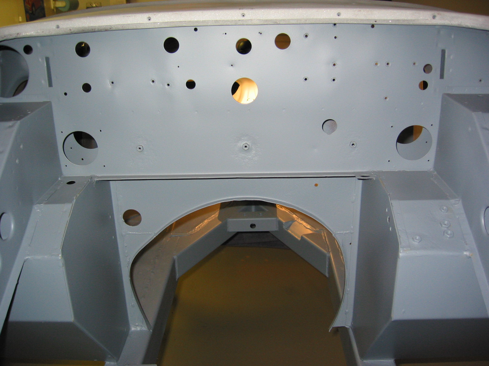
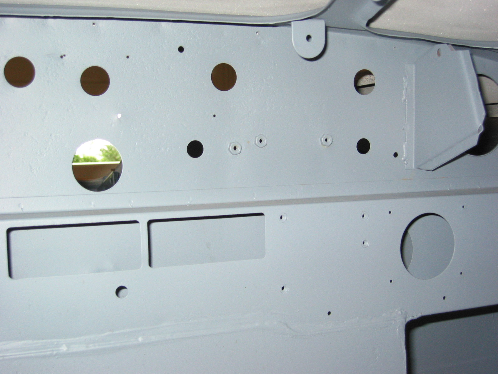
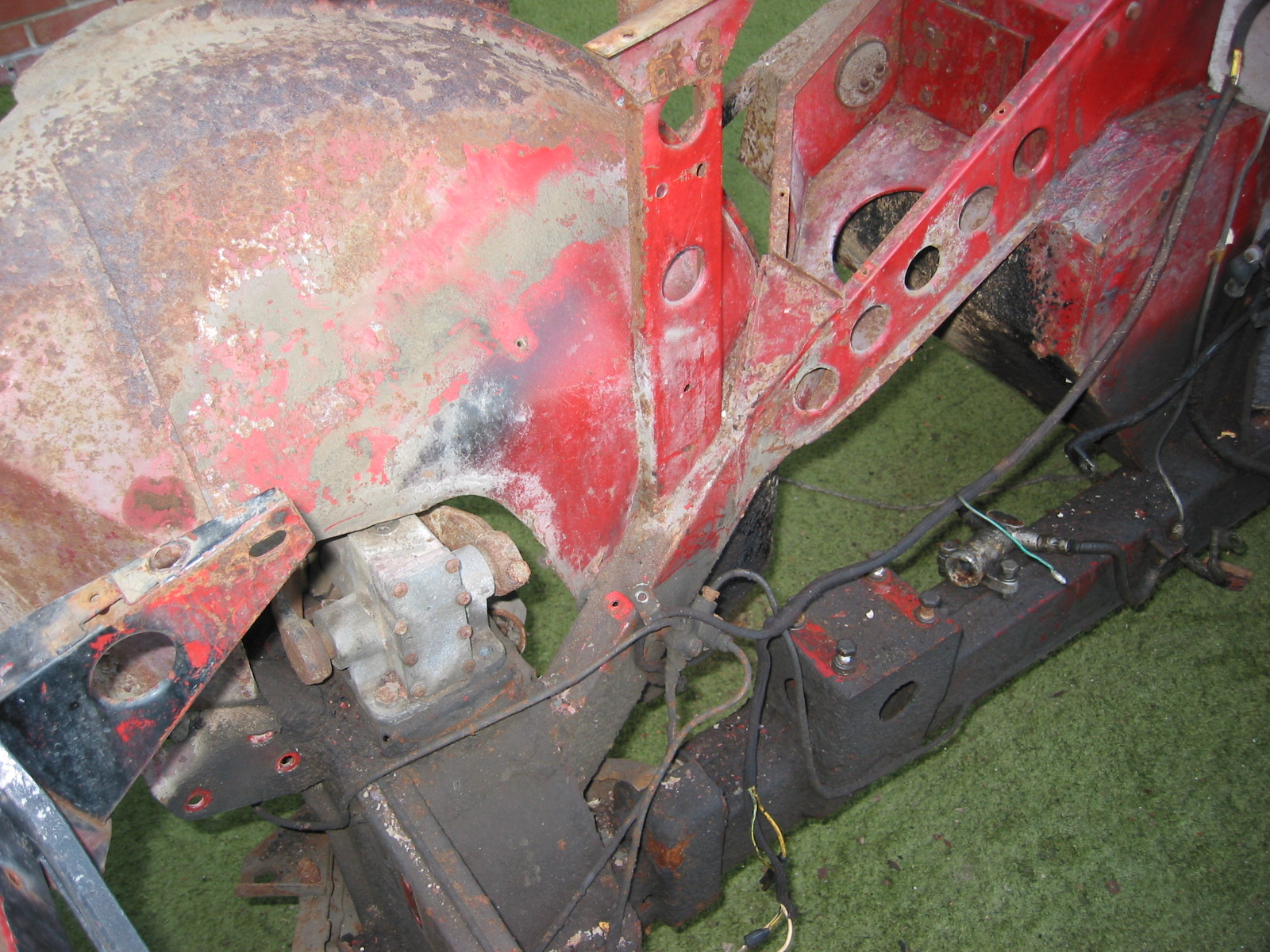
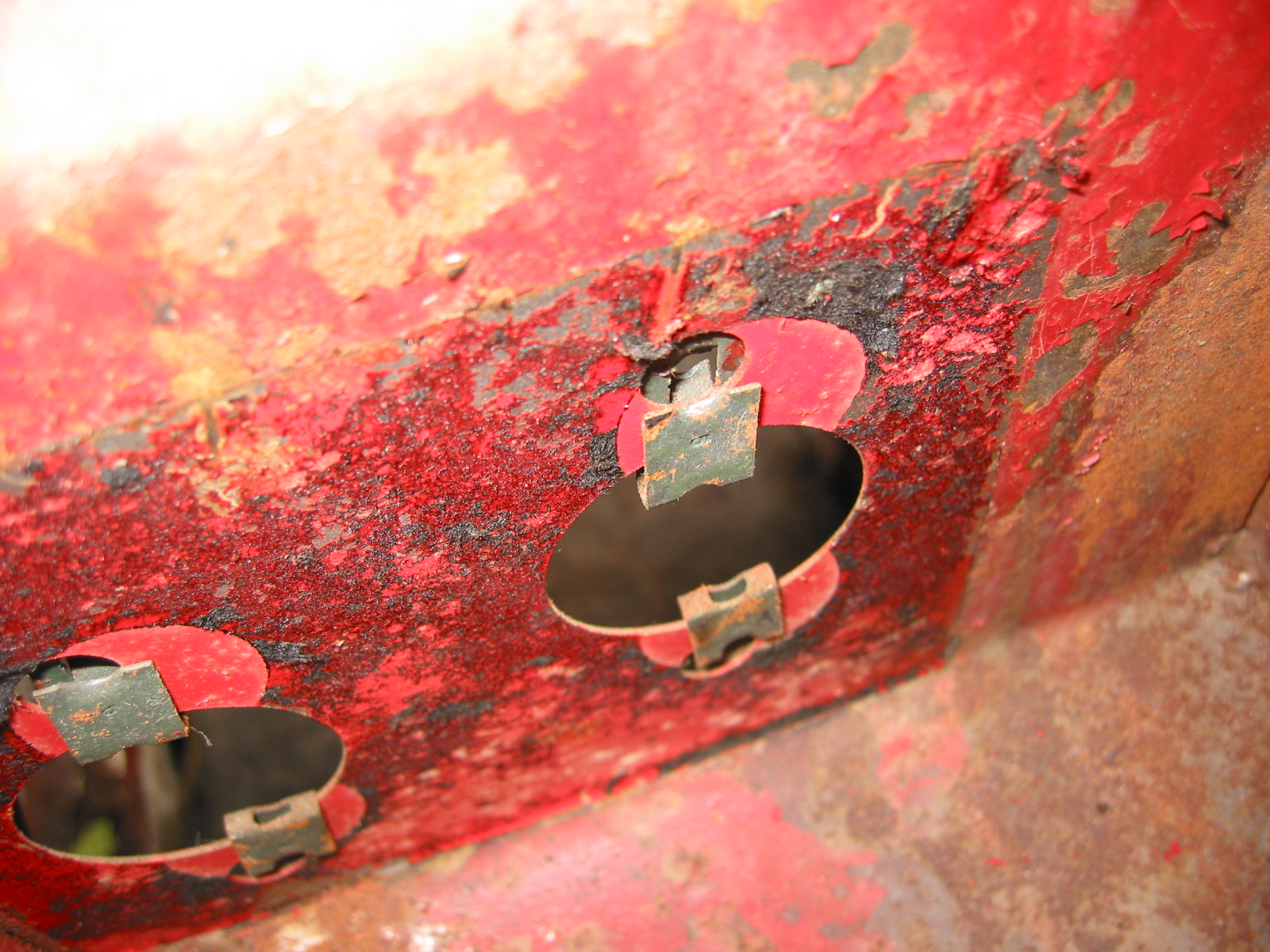
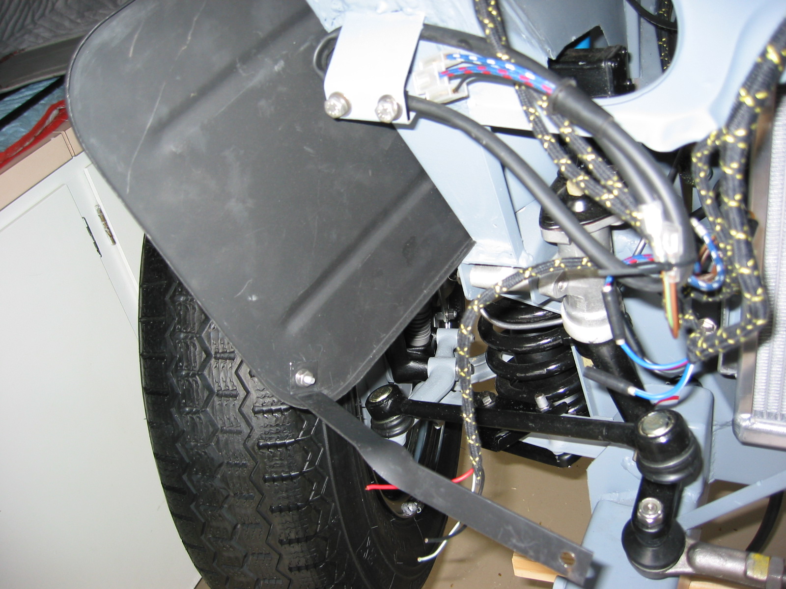
Splash Panels – Installed left and right splash panels. I needed to drill 4 new holes on each side of the car in the frame uprights. The left side was difficult and took some hammering and grinding but eventually got it to fit. Use 8 #10 1/2” pan screws to secure.
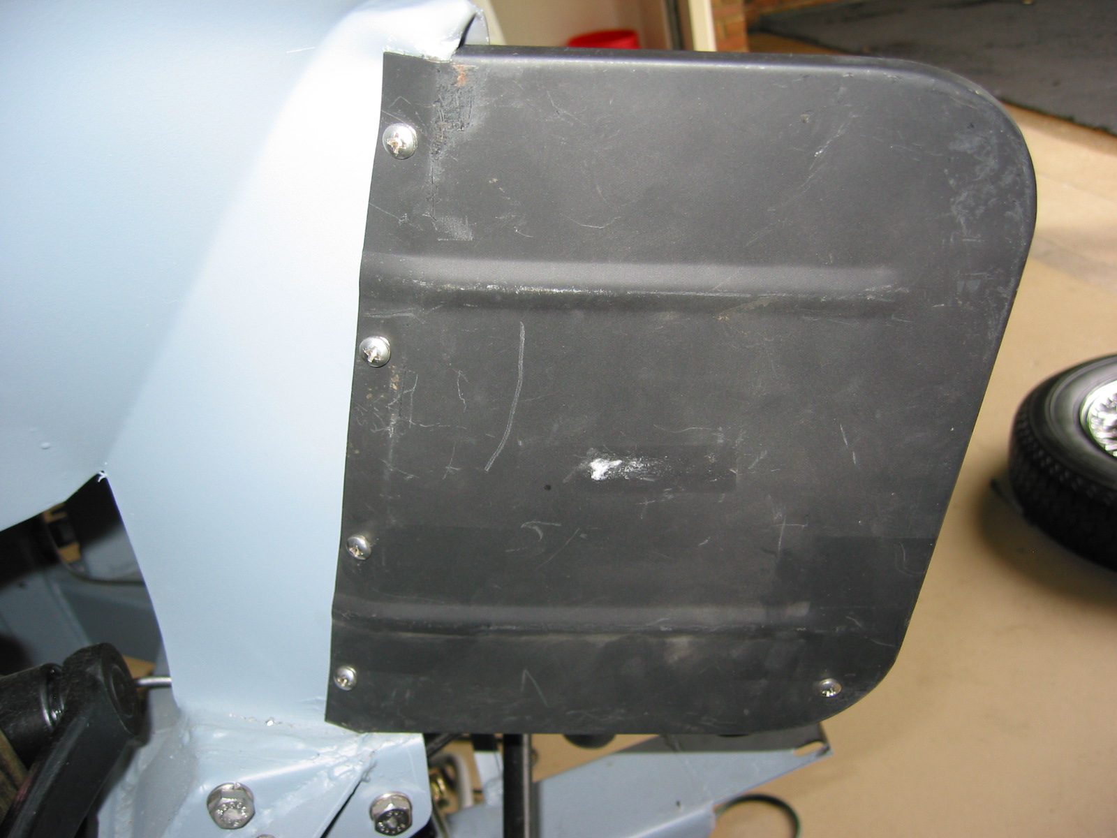
Right splash panel 1
Right splash panel 2
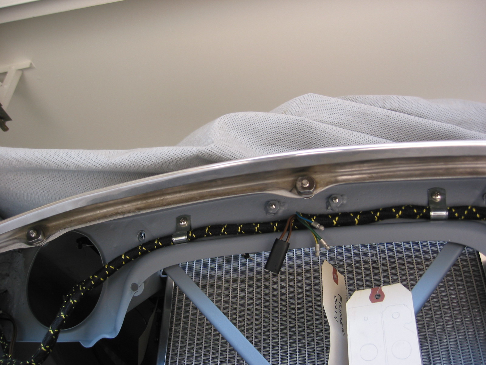
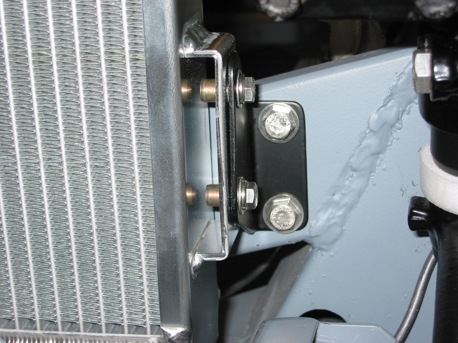
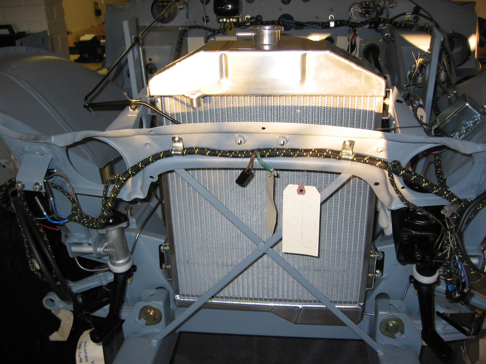
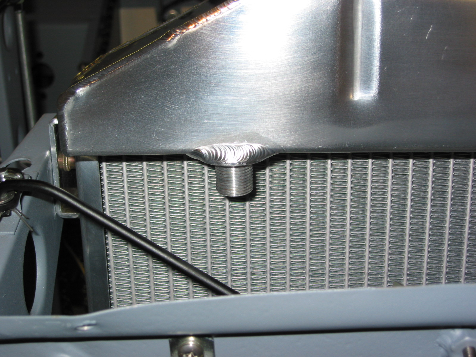
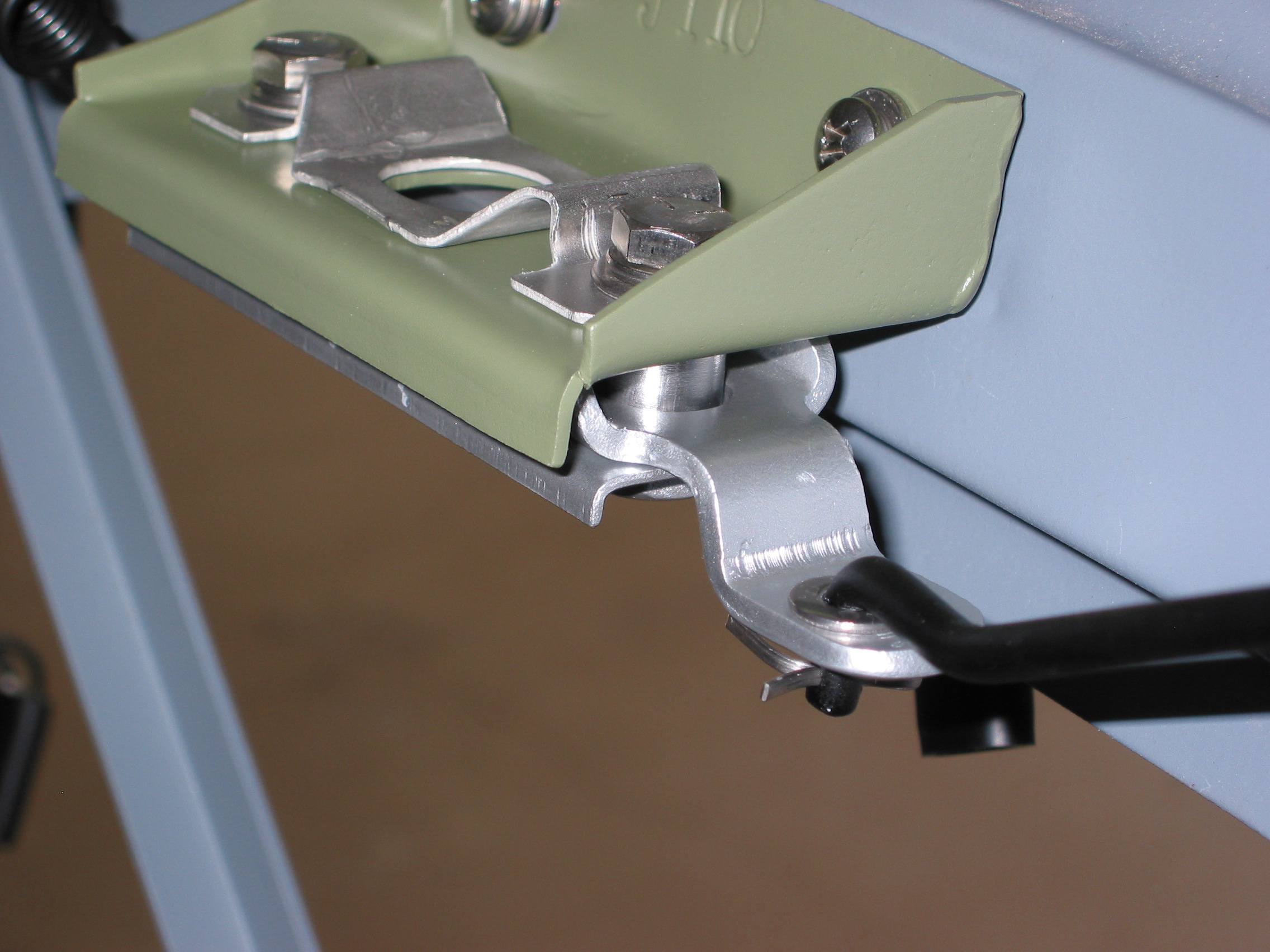
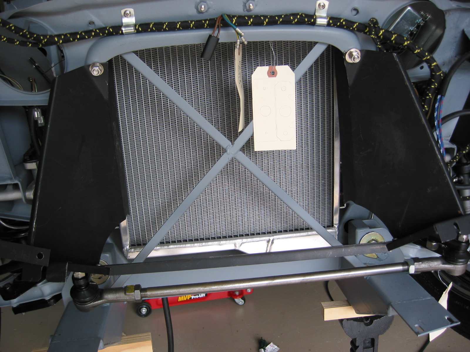
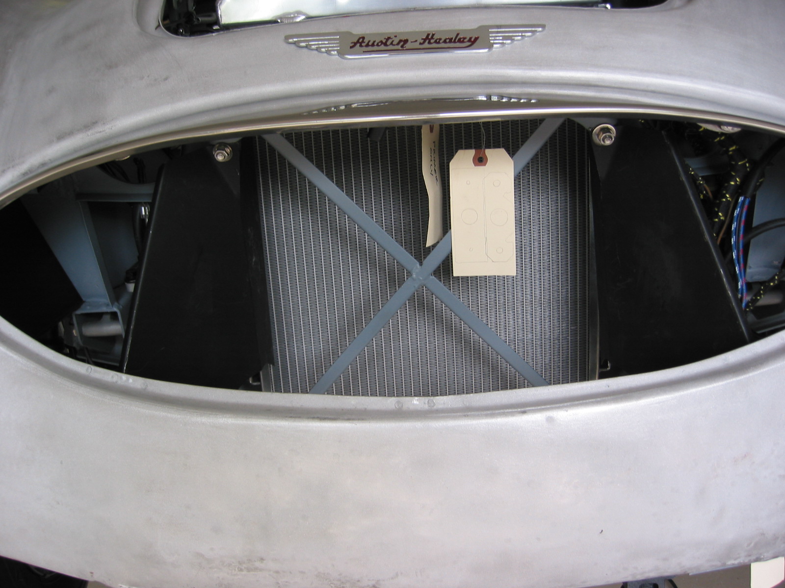
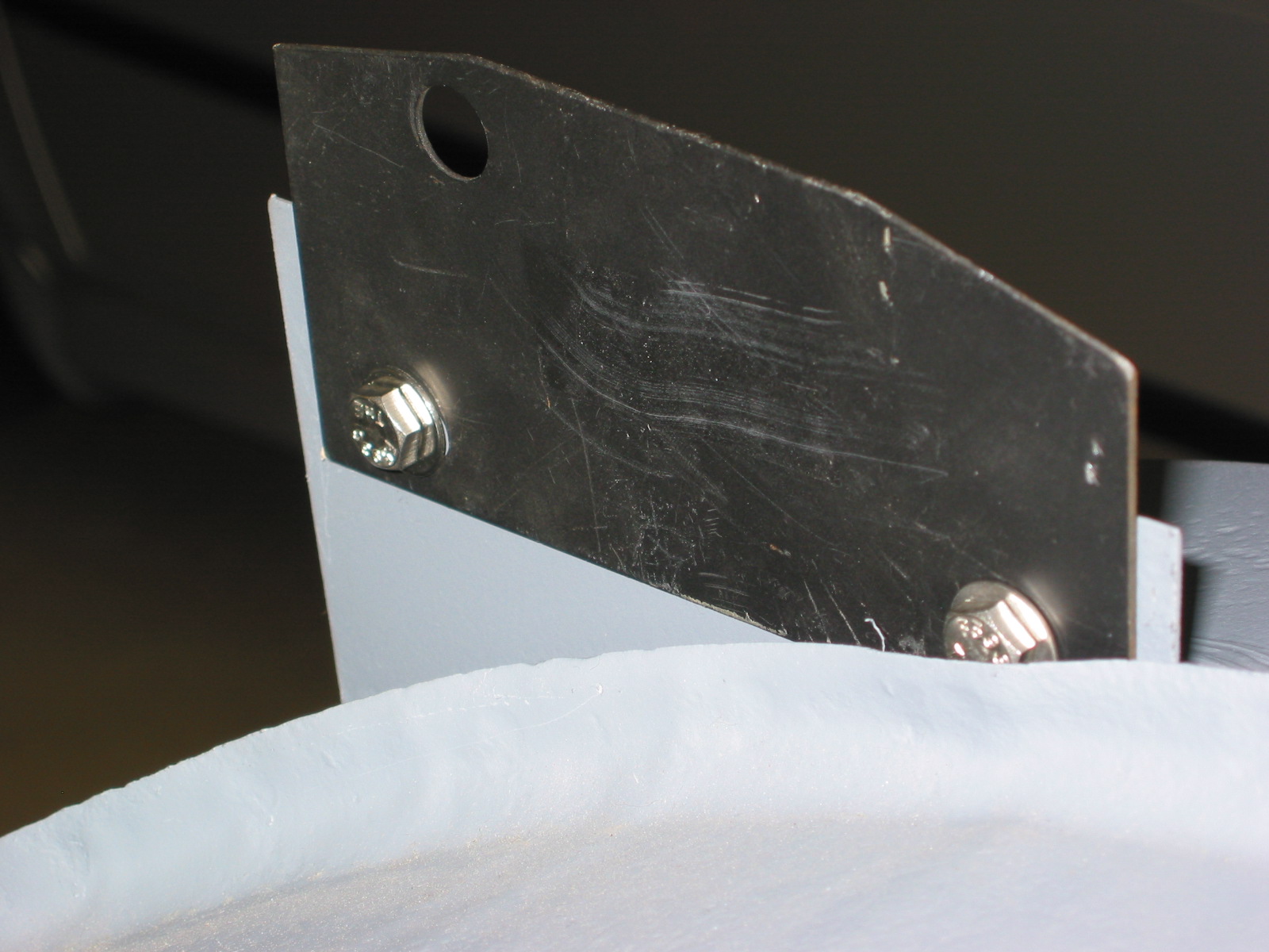
Radiator Air Deflector – Installed radiator air deflector with two 5/16” x 5/8” bolts.
Air deflector 3
Air deflector 1
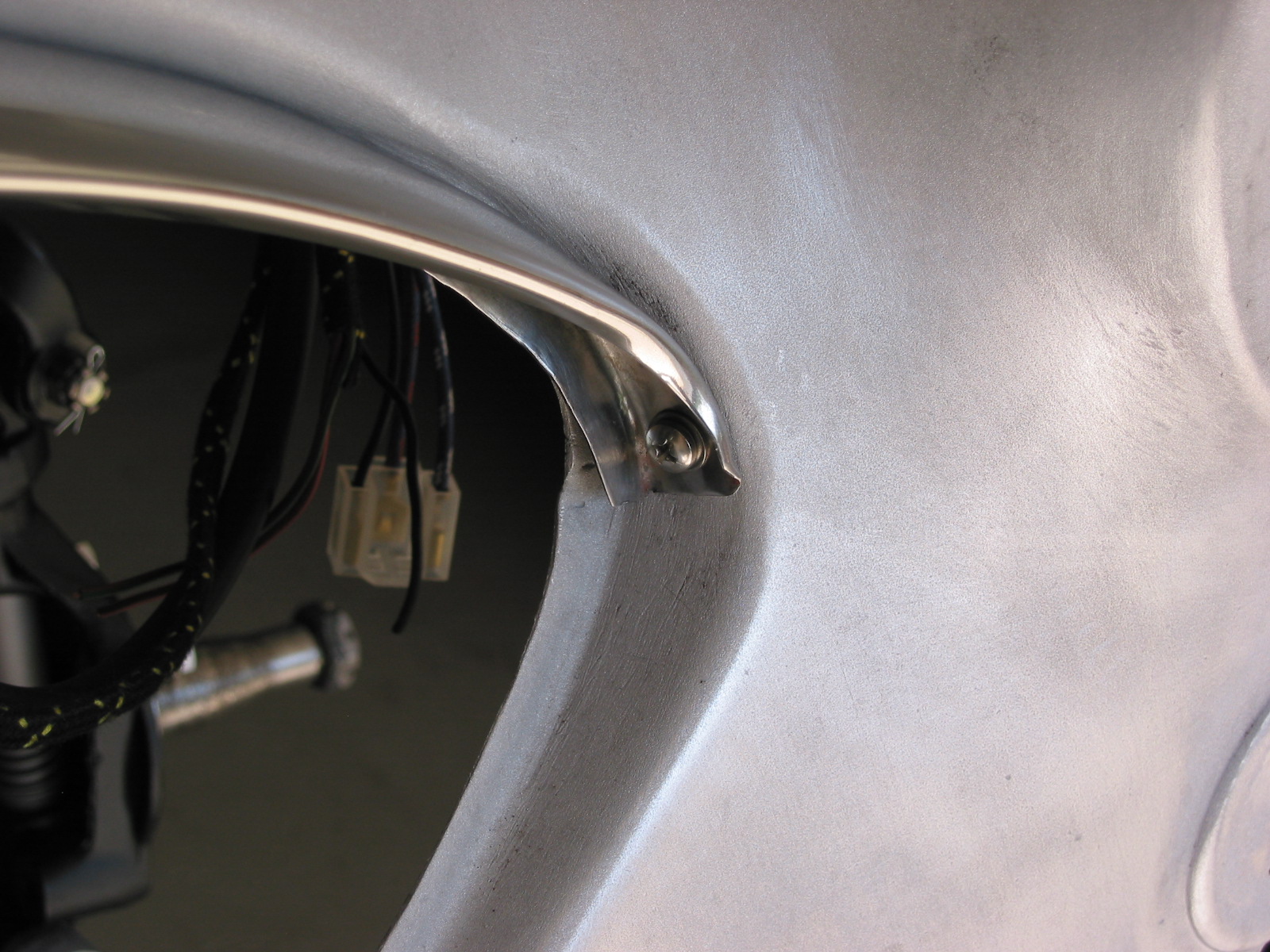
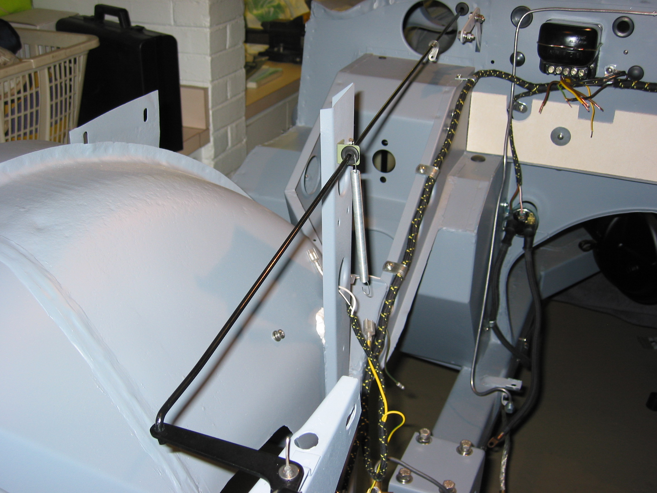
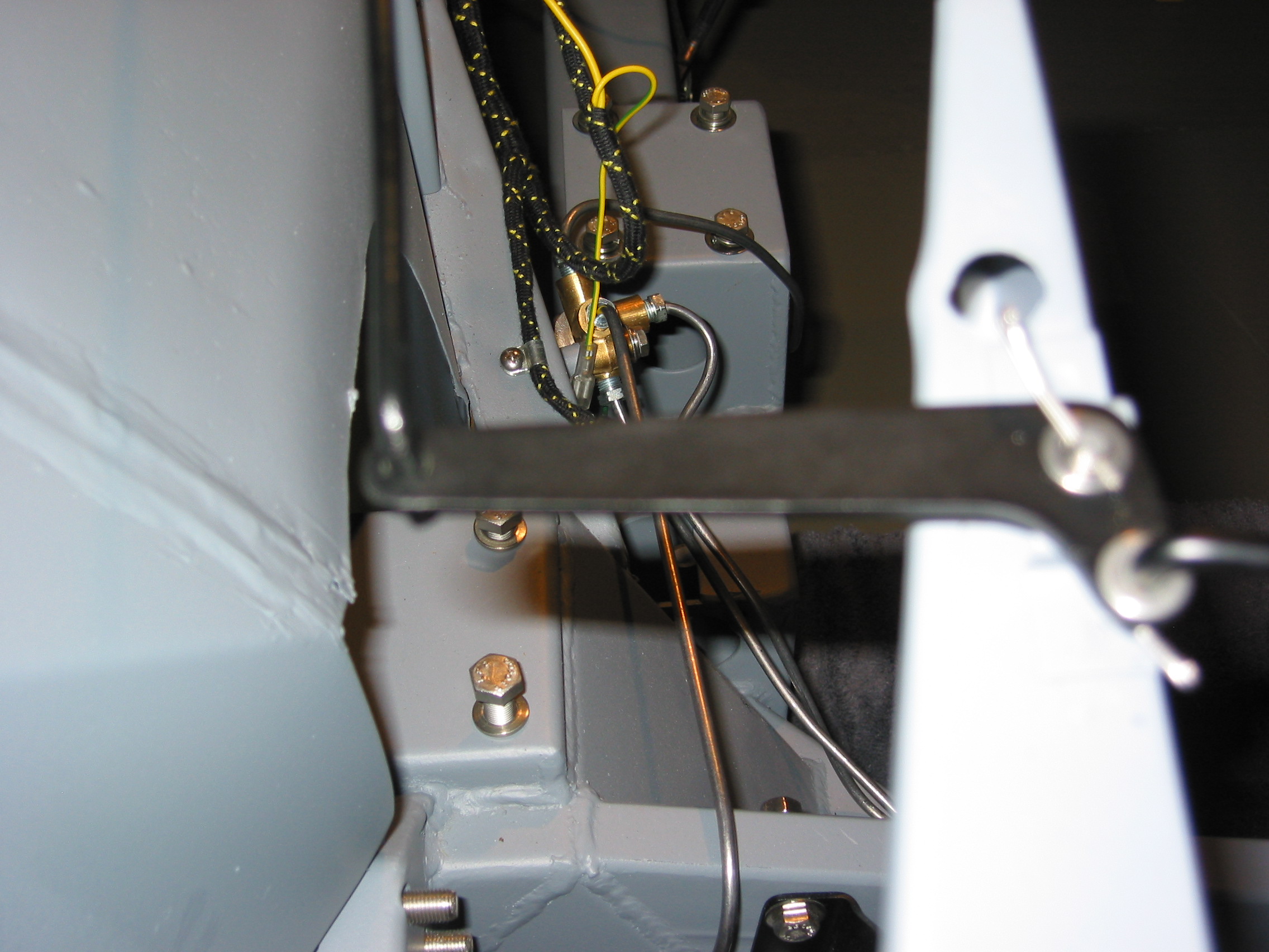
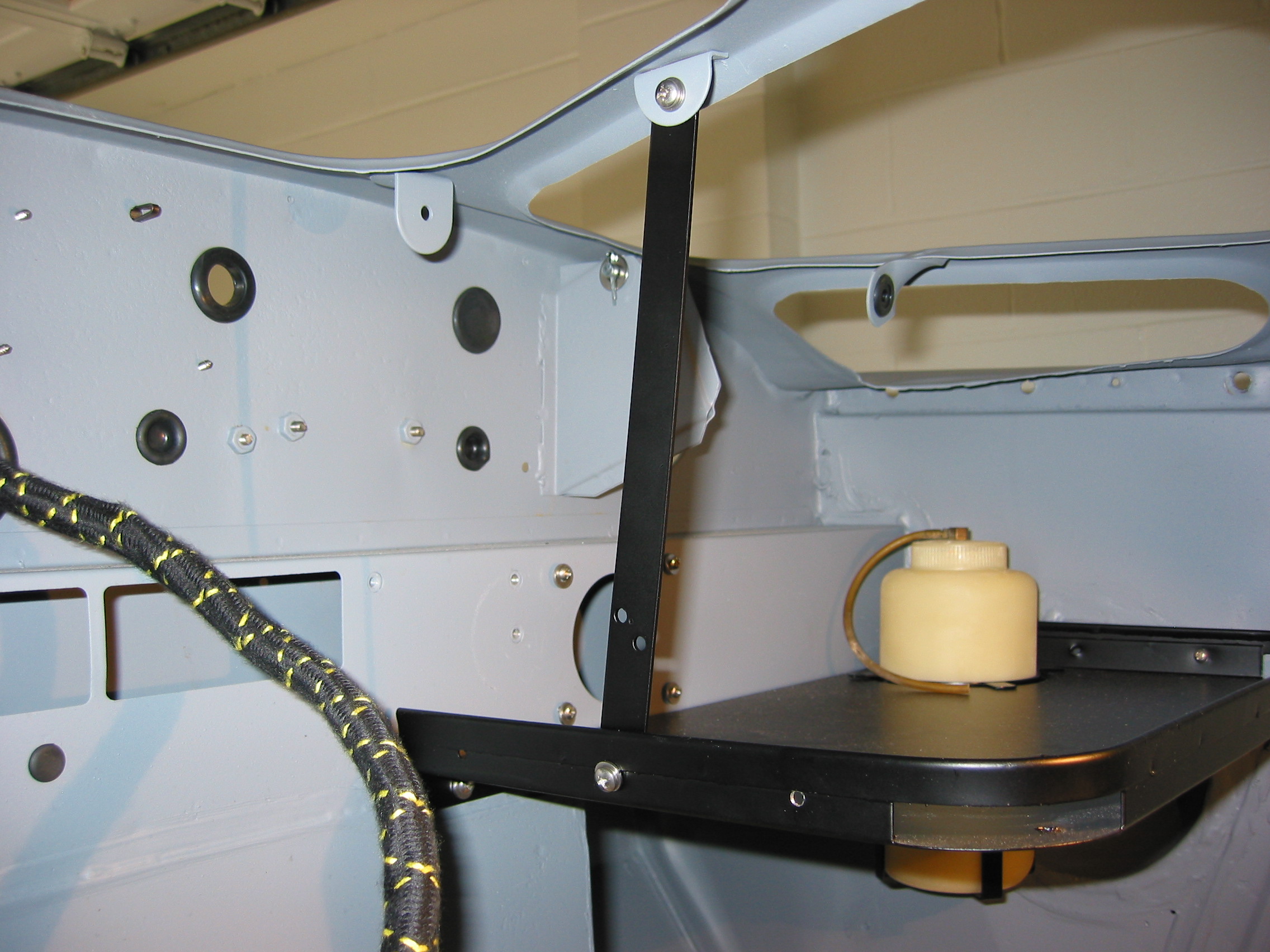
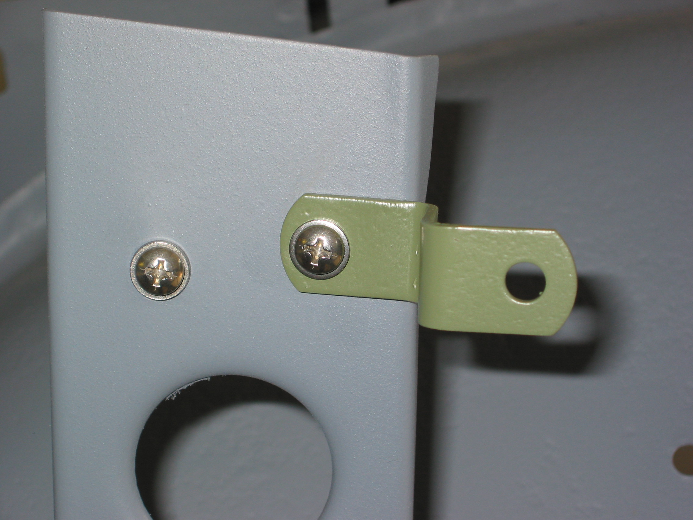
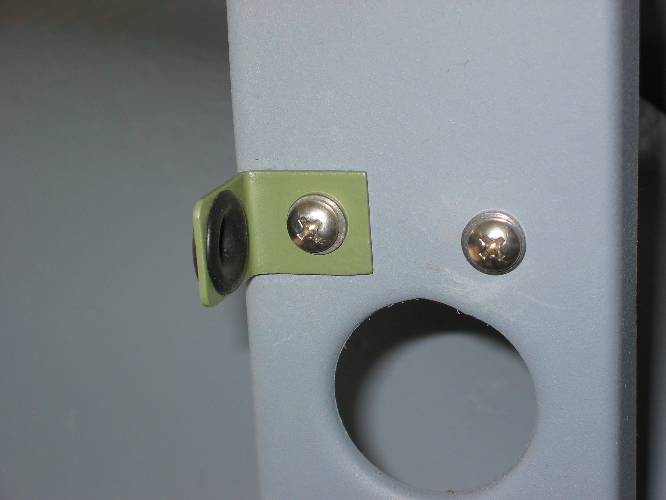
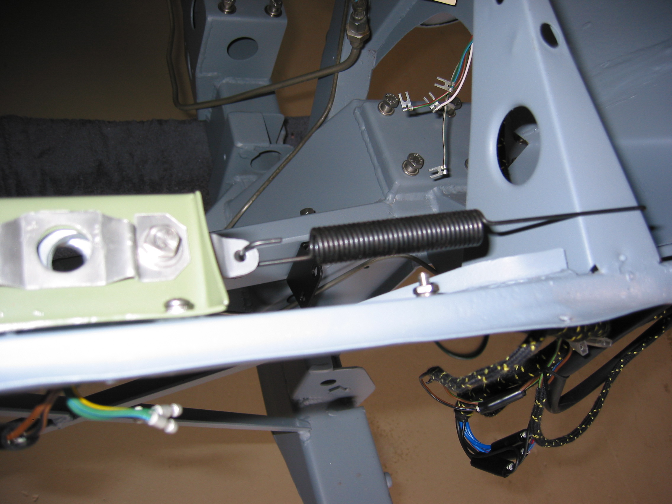
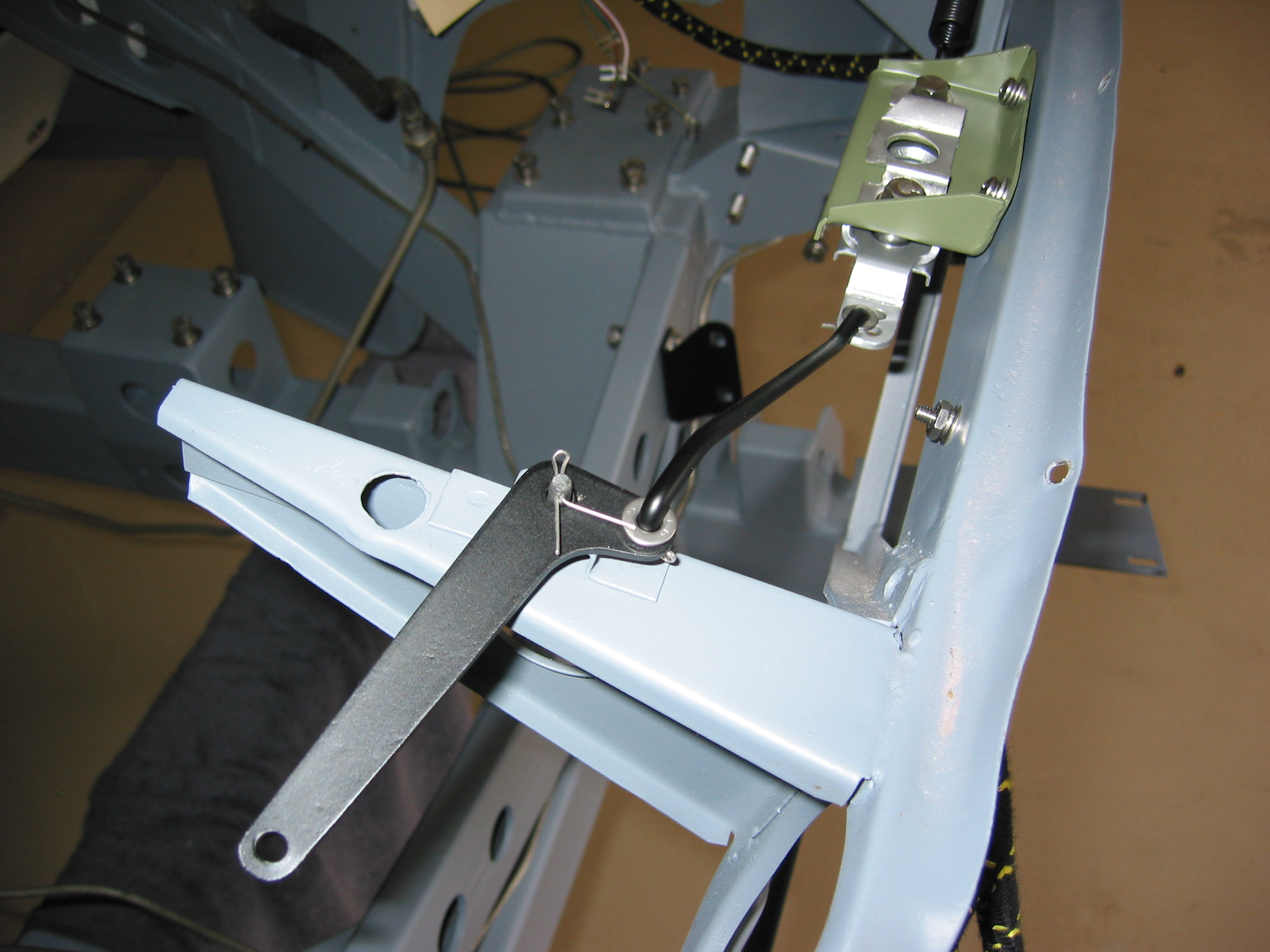
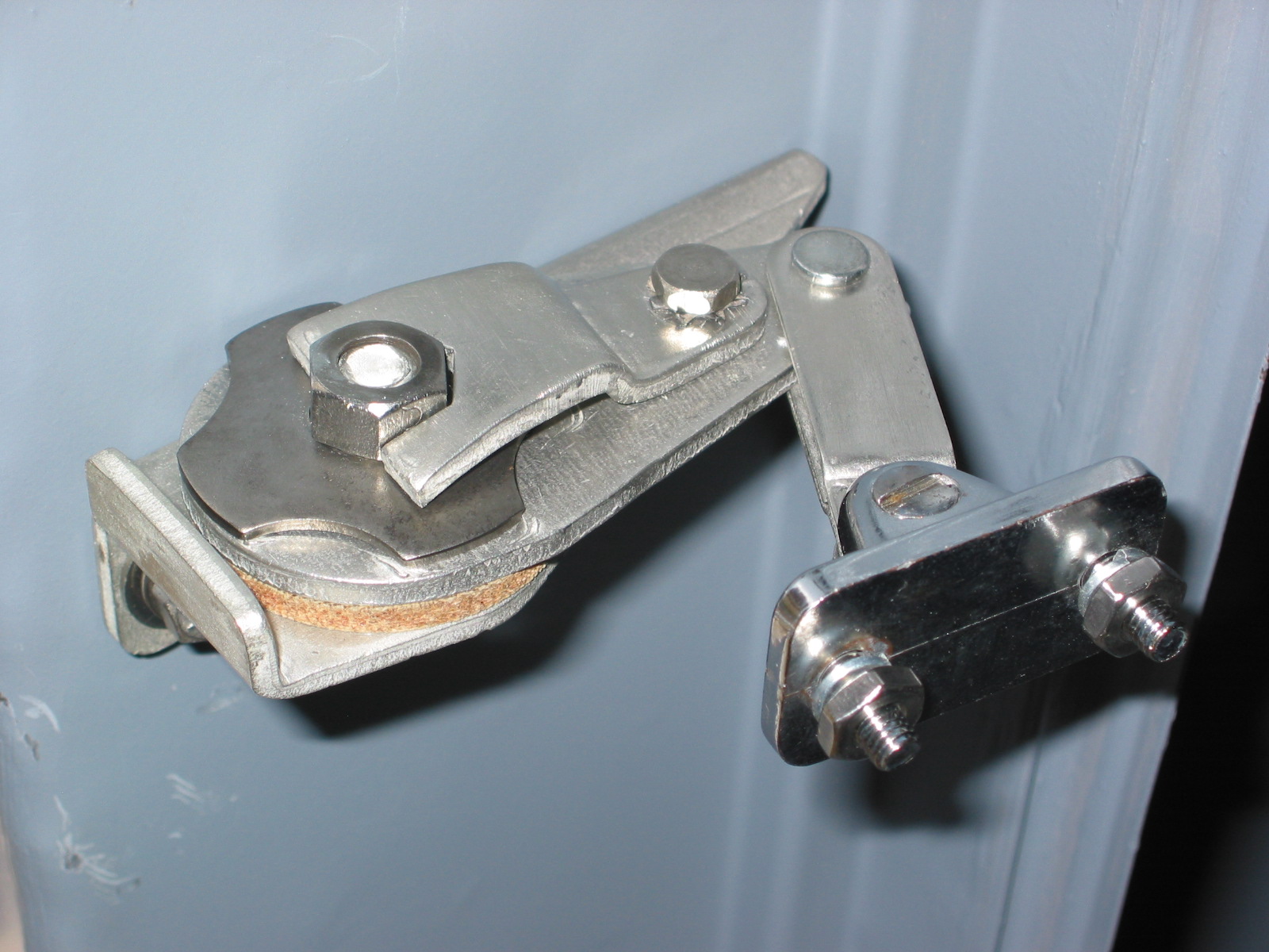
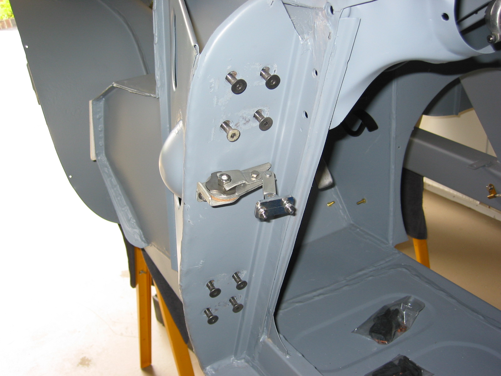
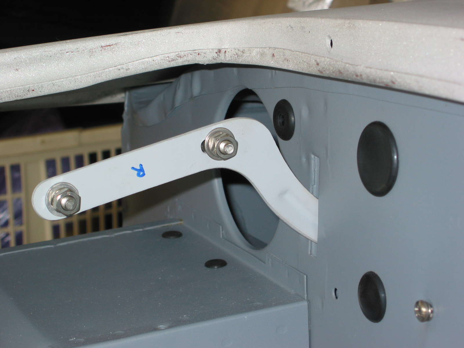
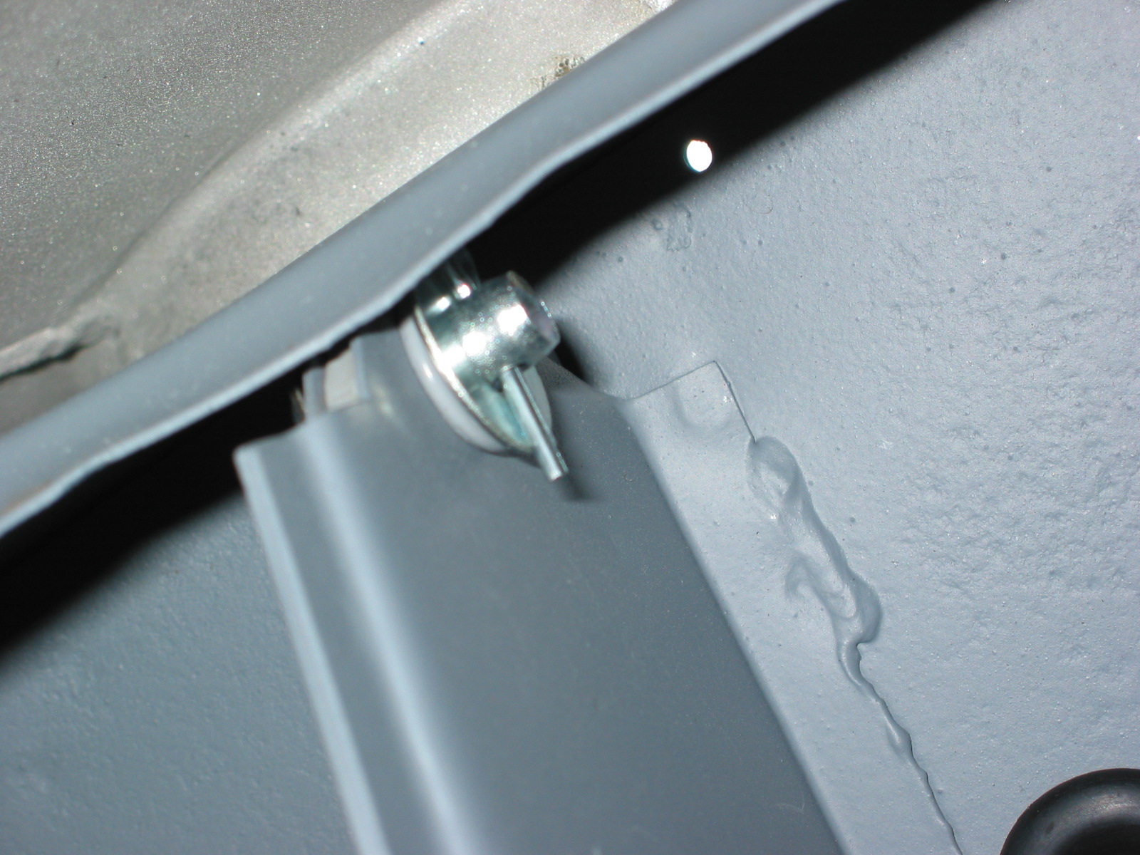
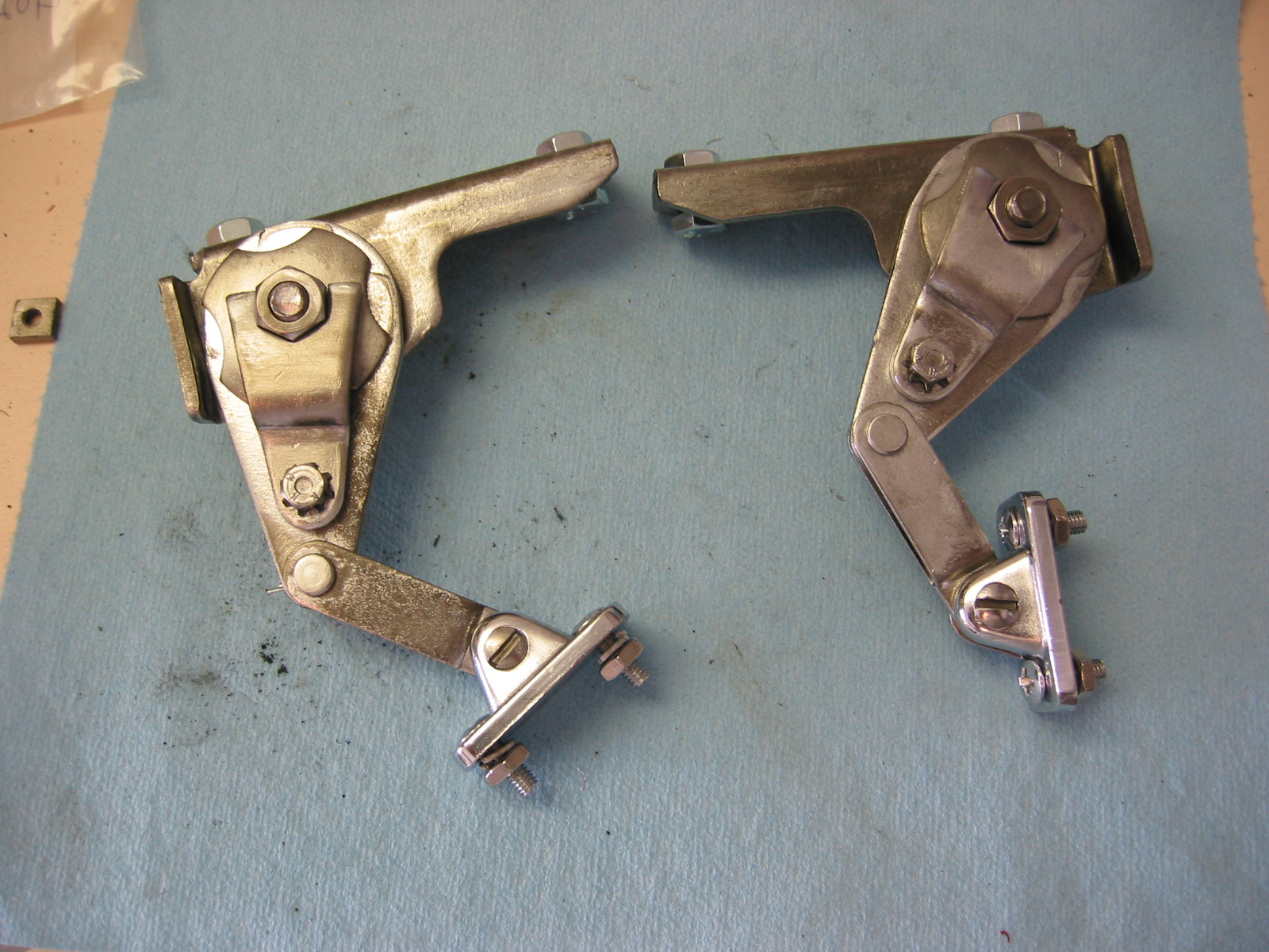
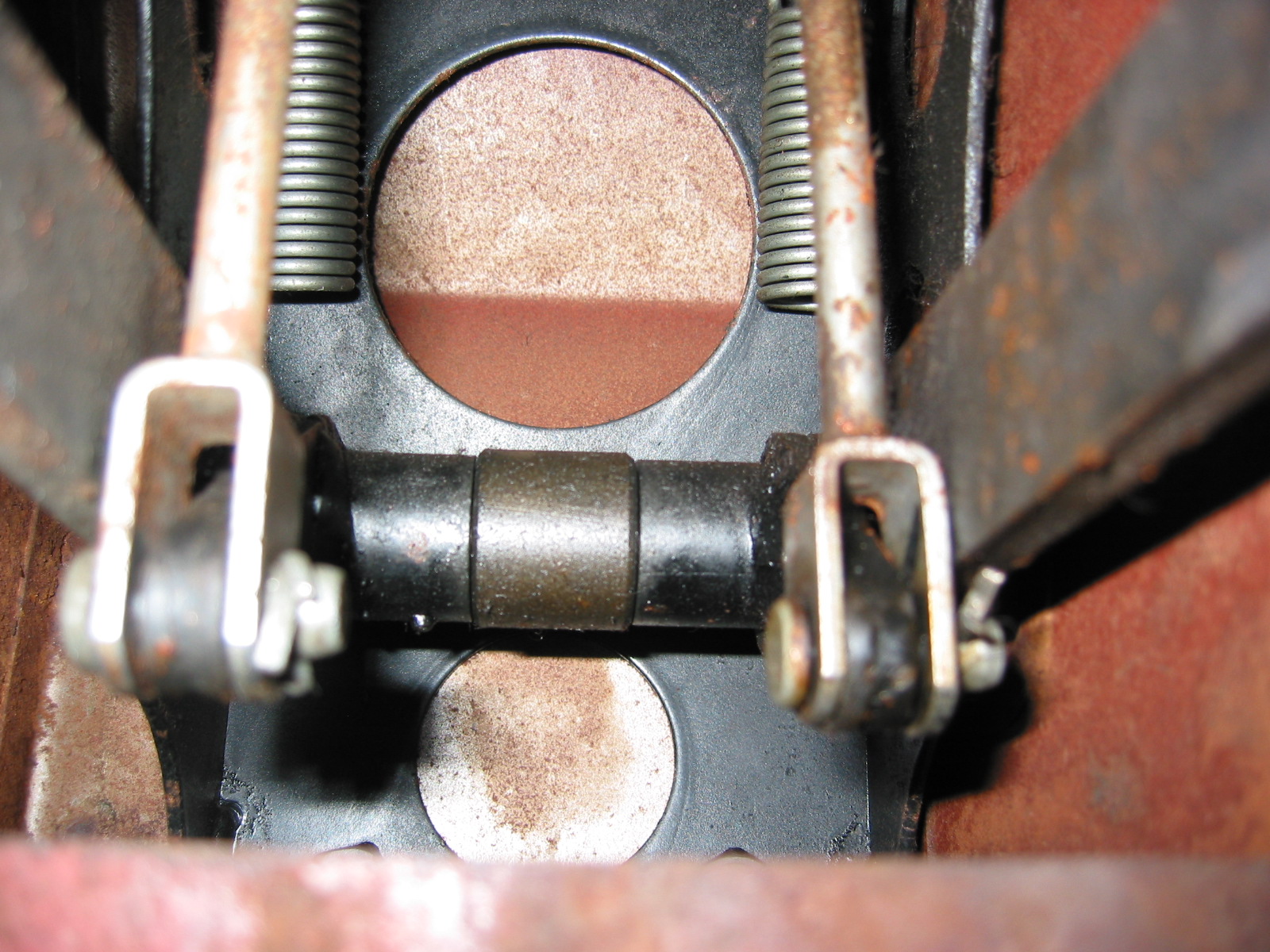
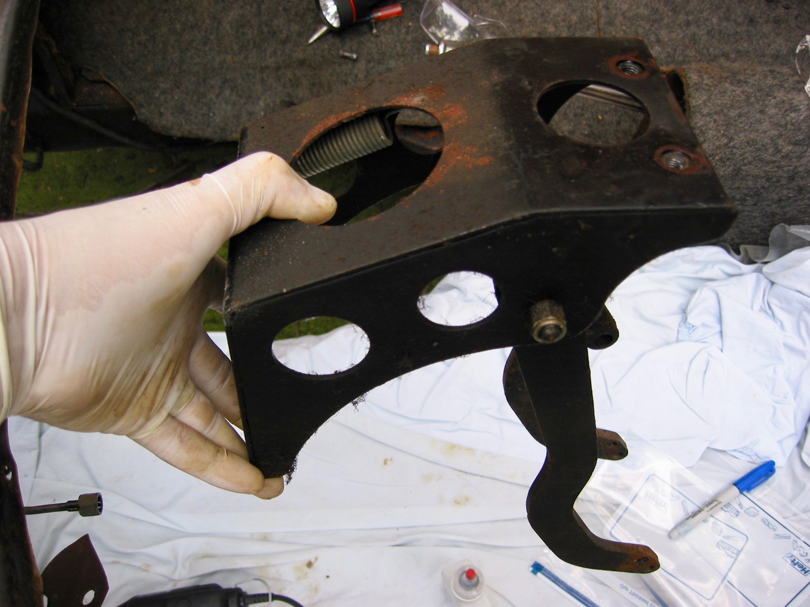
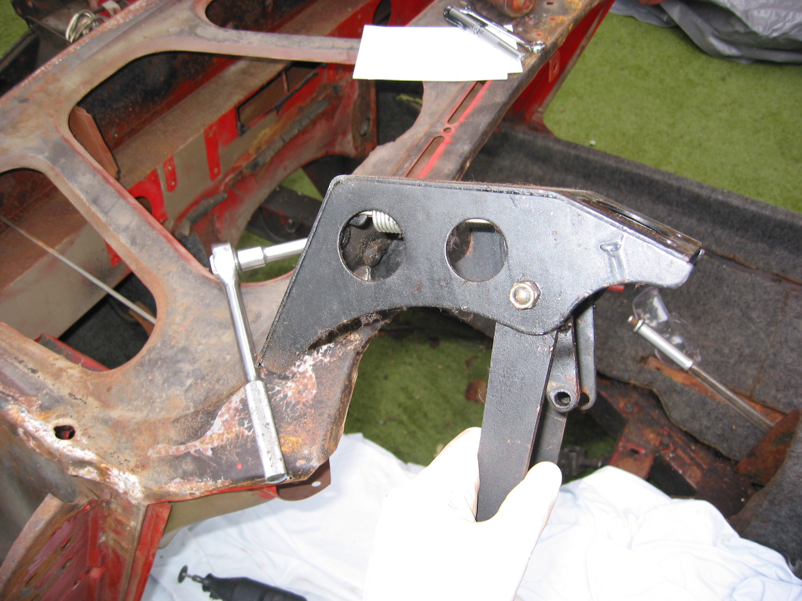
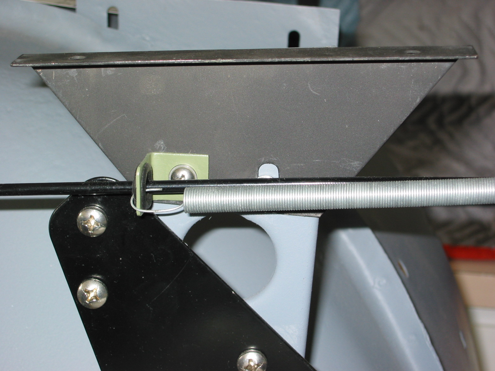
Bonnet Upright Brackets – Note the way they are mounted in the photos.
RH Bonnet opening brace 2

LH Bonnet opening brace 3
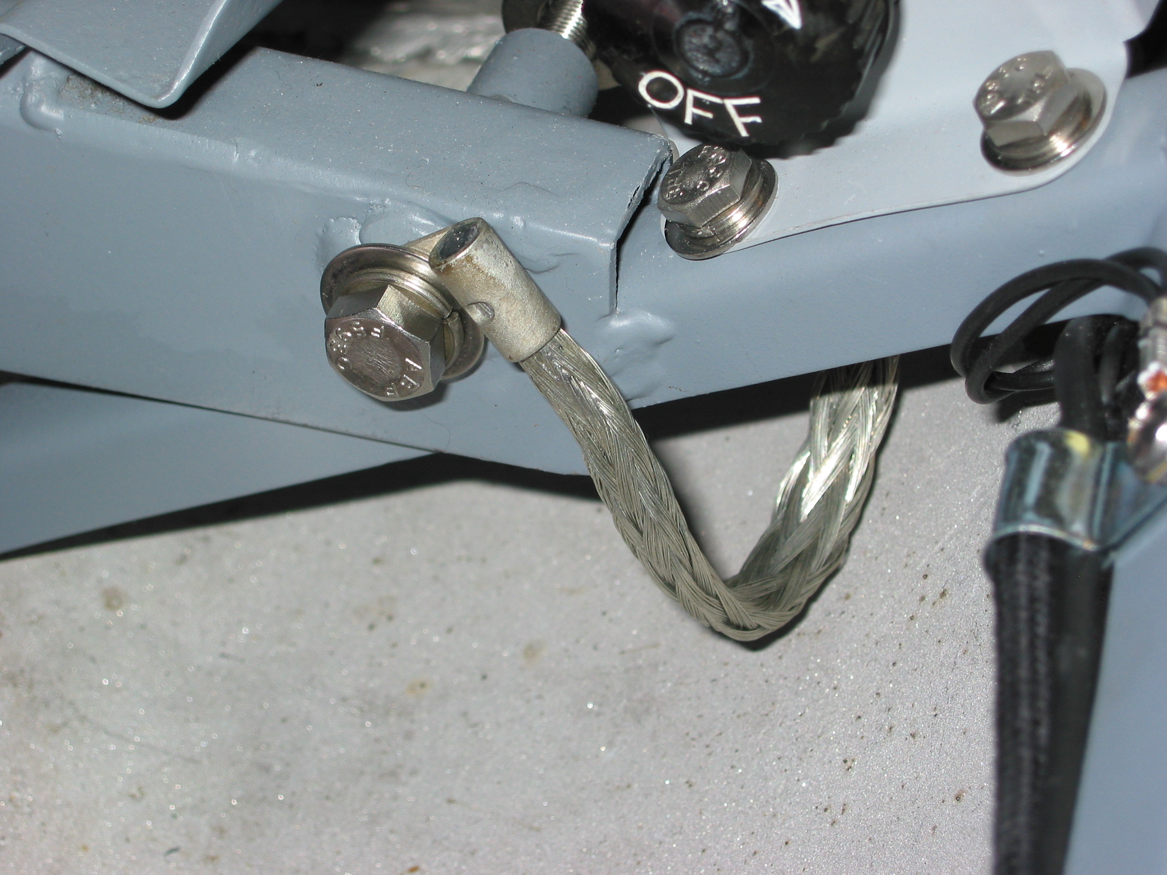
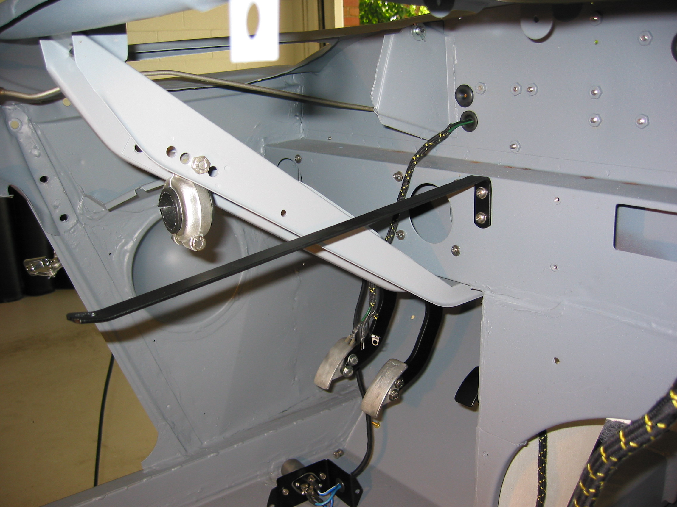
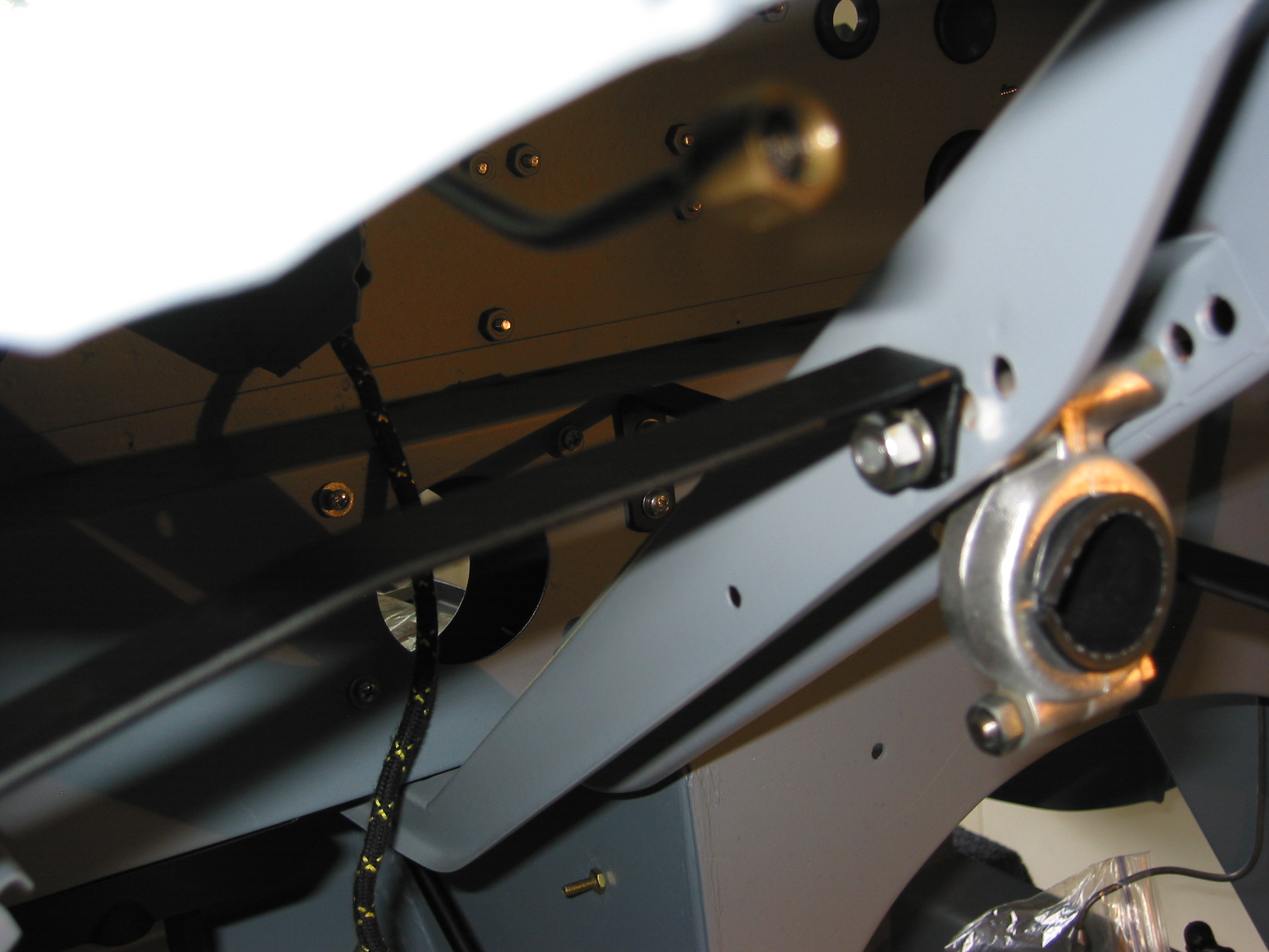
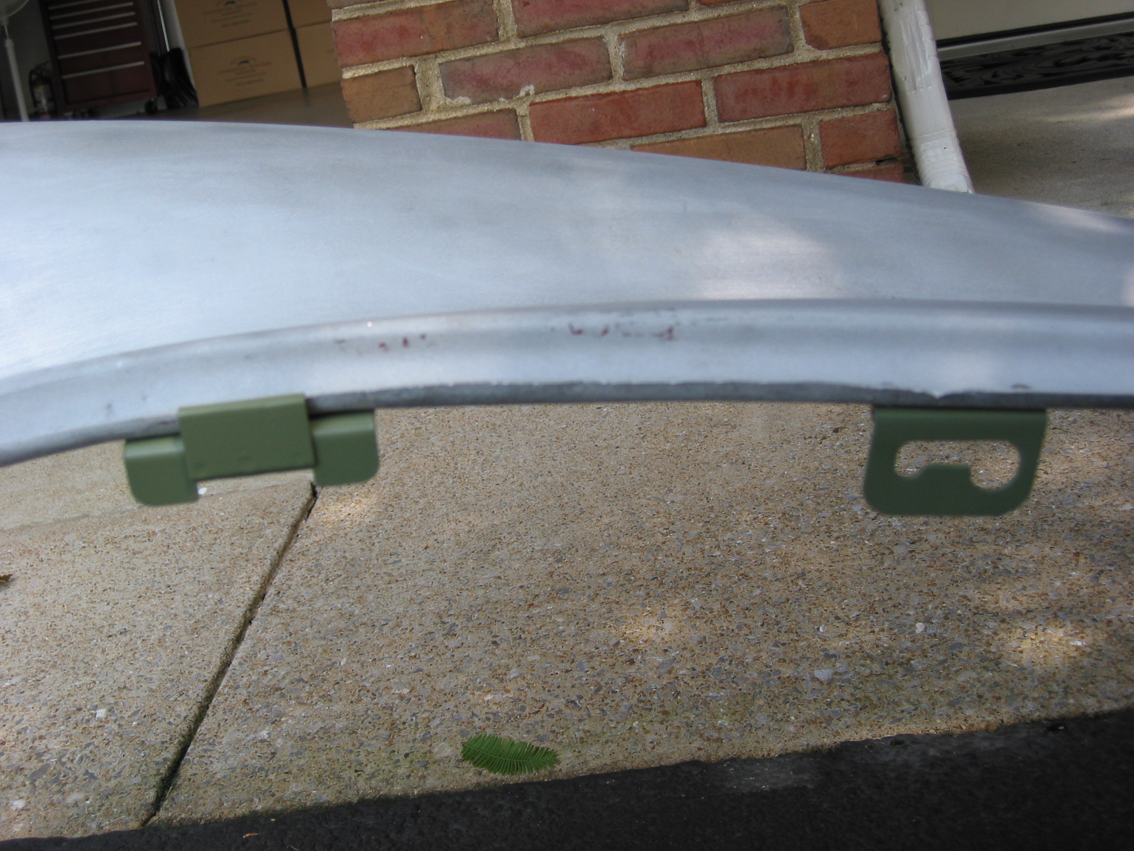
Front Wing Mounting Brackets – Installed left and right front wing support brackets using 4 1/4” x 3/4” hex head bolts.

RH Shroud bracket 1
LH Shroud bracket 2
June 18, 2004
Rear Axle Revisited
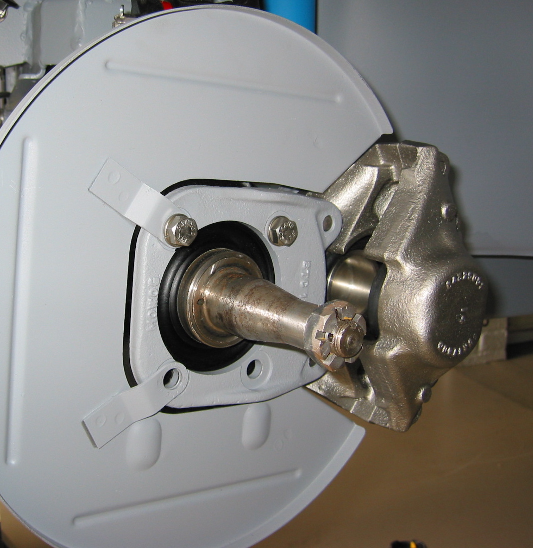
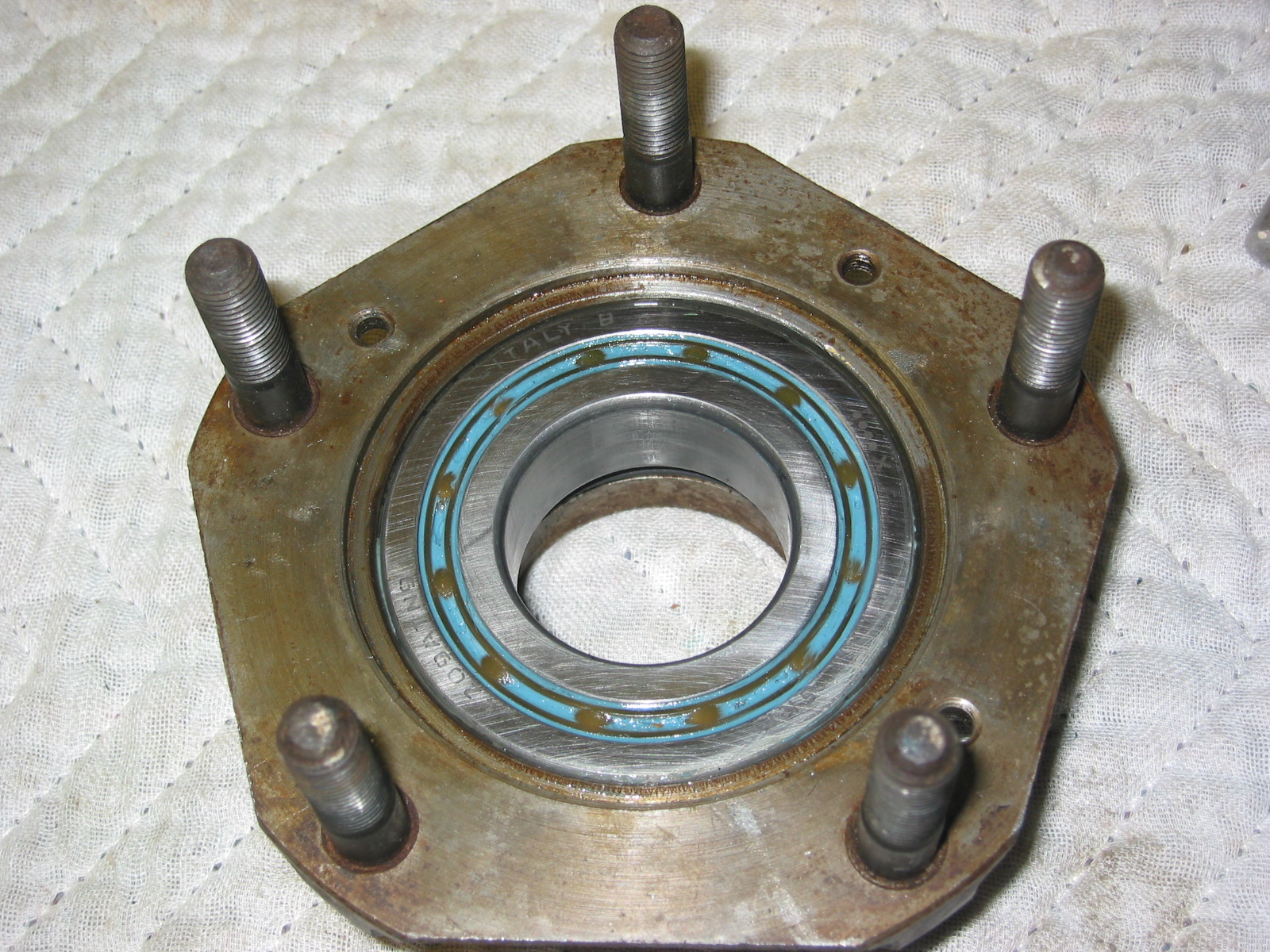
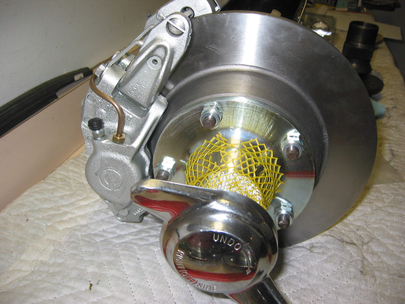
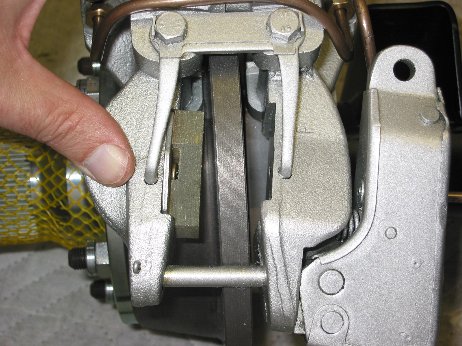
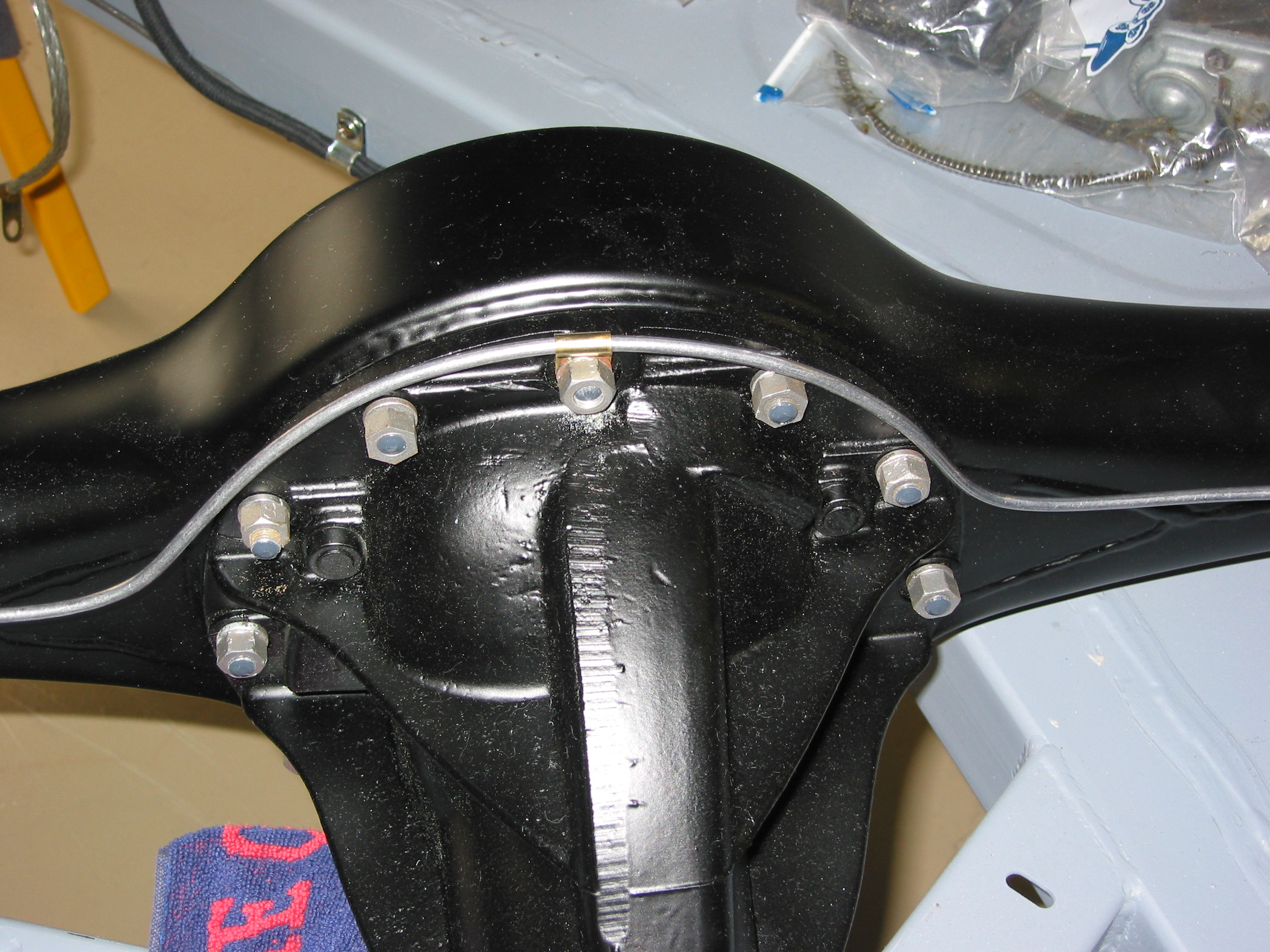
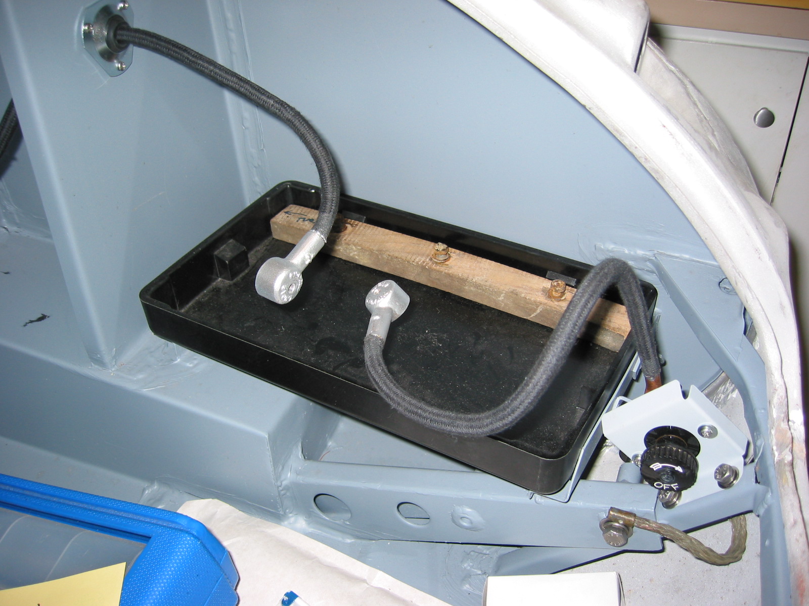
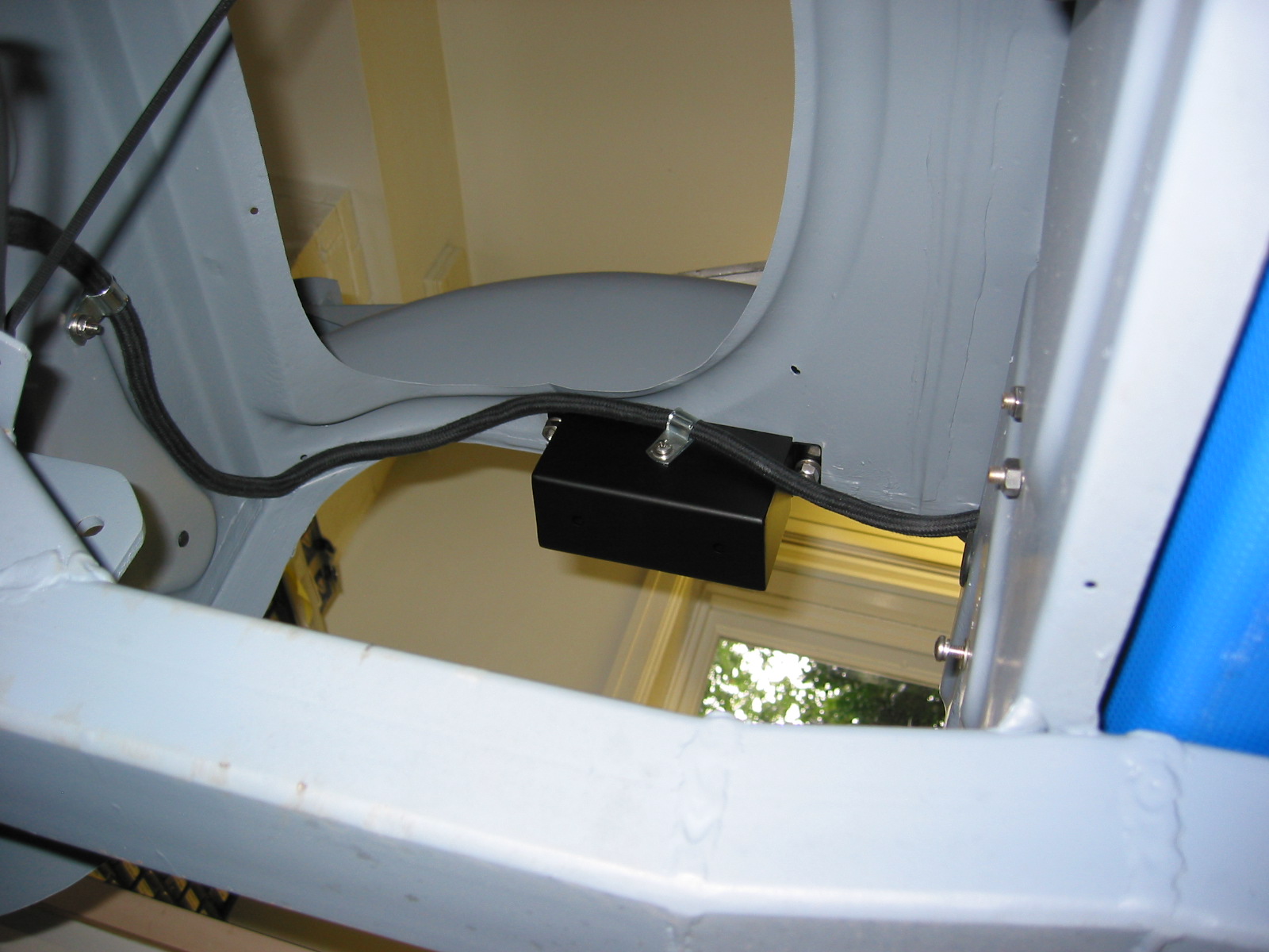
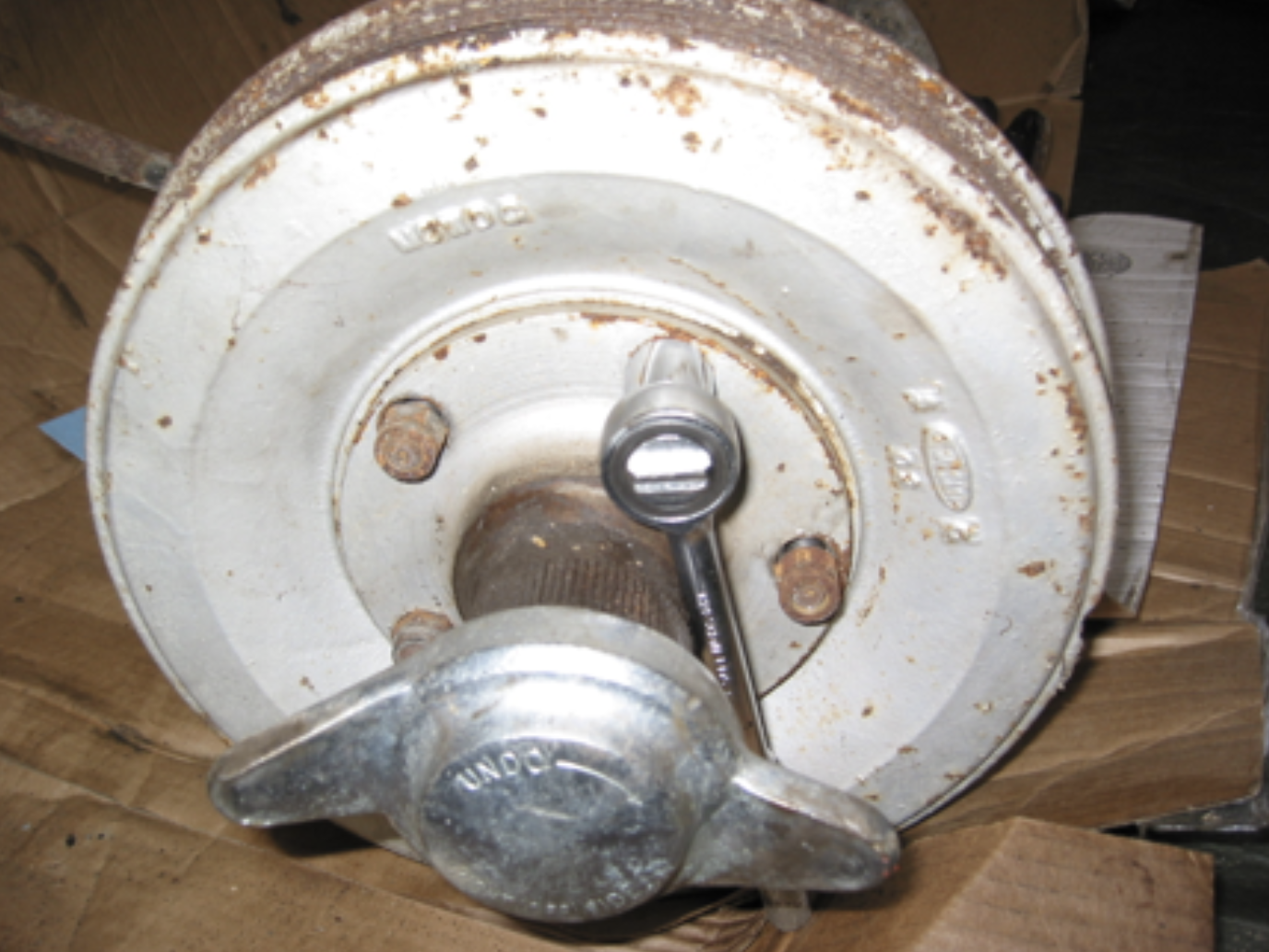
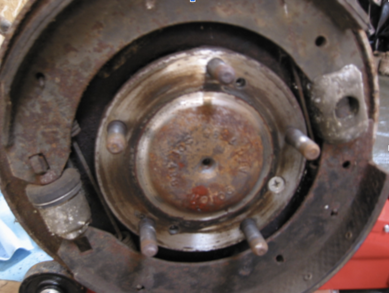
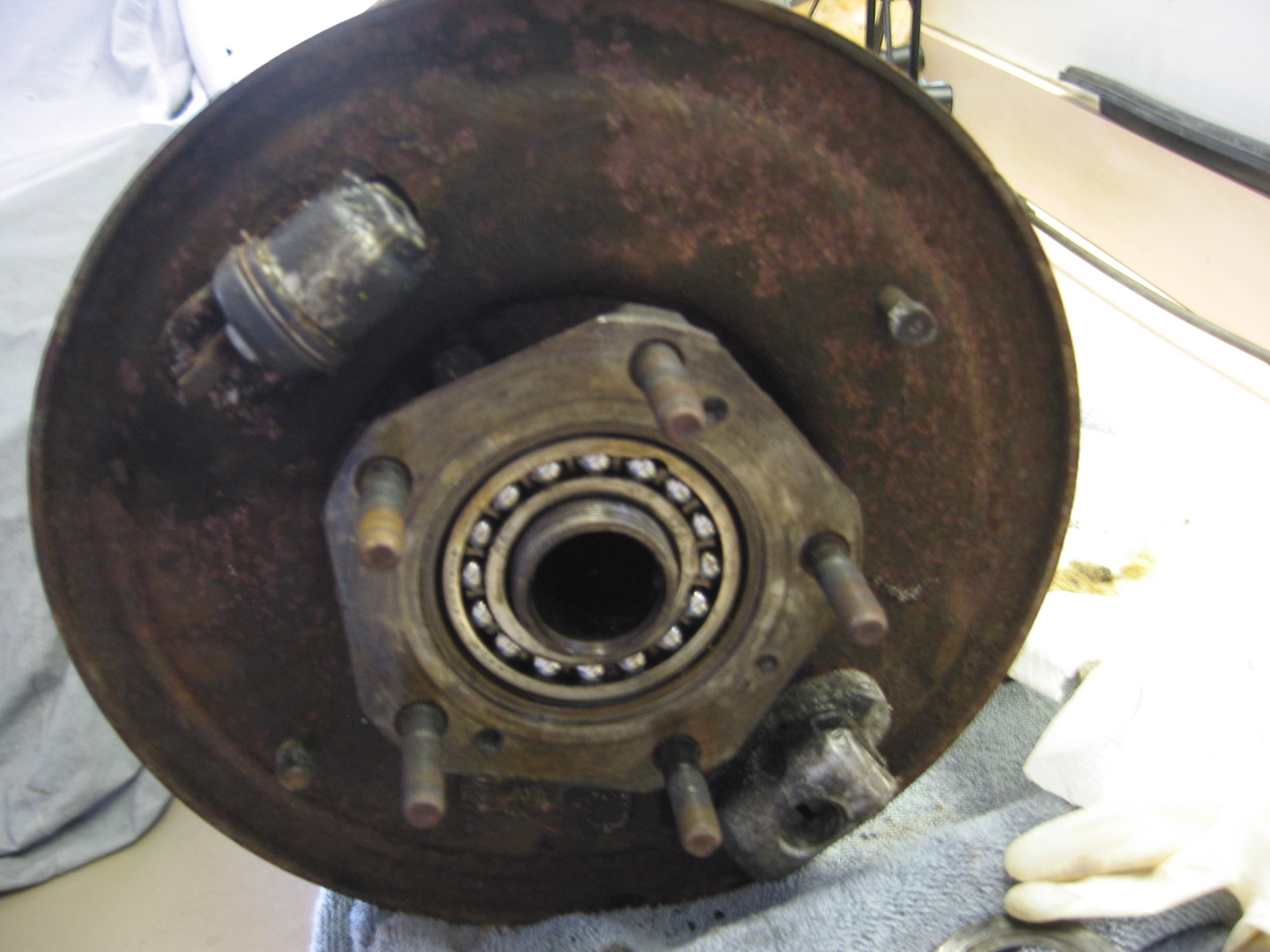
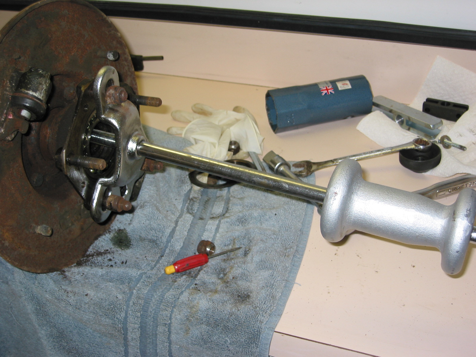
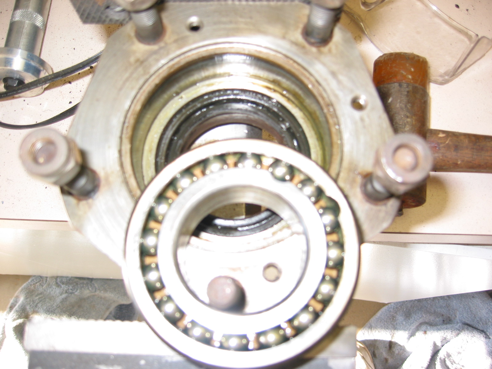
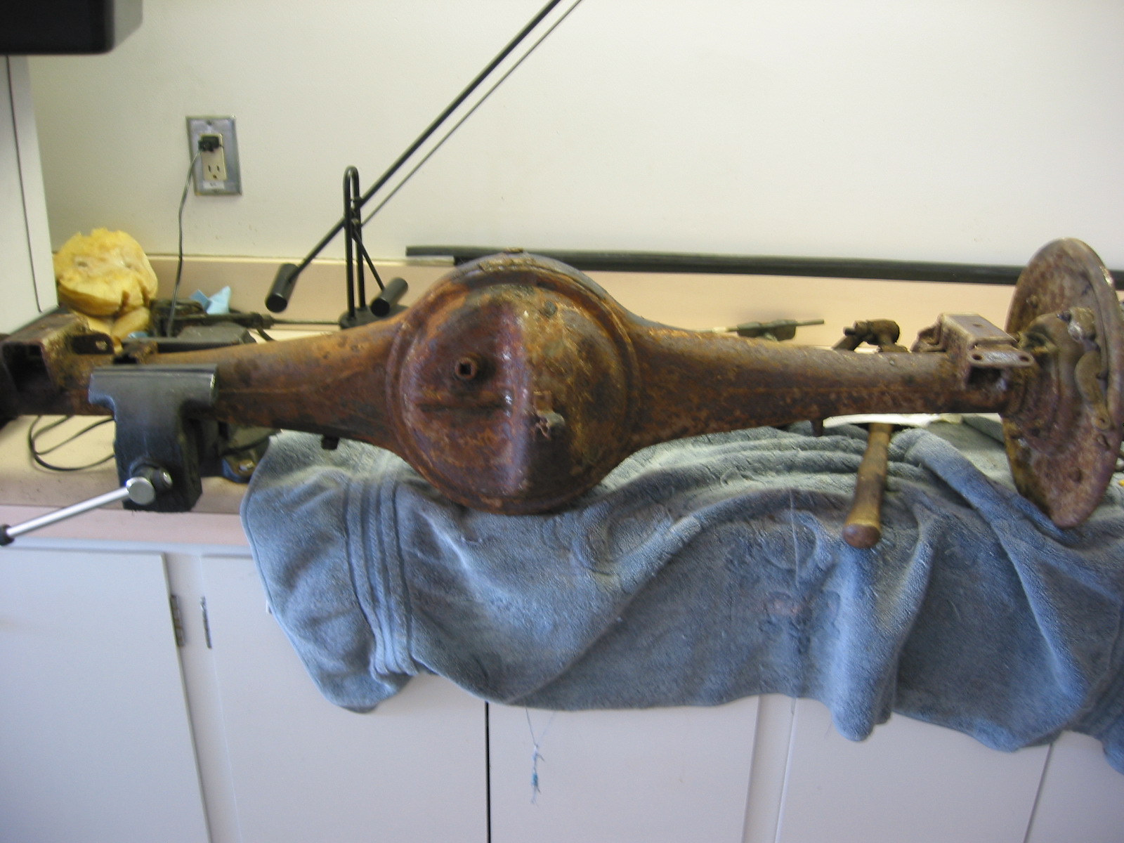
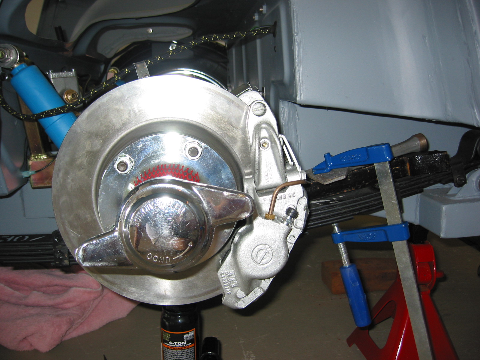
Differential – Installed the differential pumpkin and bearing caps in the differential casing. I will be installing the 3.44 crown and pinion in the car when it is drivable, but to get a rolling chassis I just put the old differential back in with no pinion gear. Fastened the differential to the axle and inserted the half shafts and tightened them down with the small locating flat head screws. Affixed the rear brake disc rotors and calipers fastened the hub extensions to the axle with the 5 locking hub nuts.
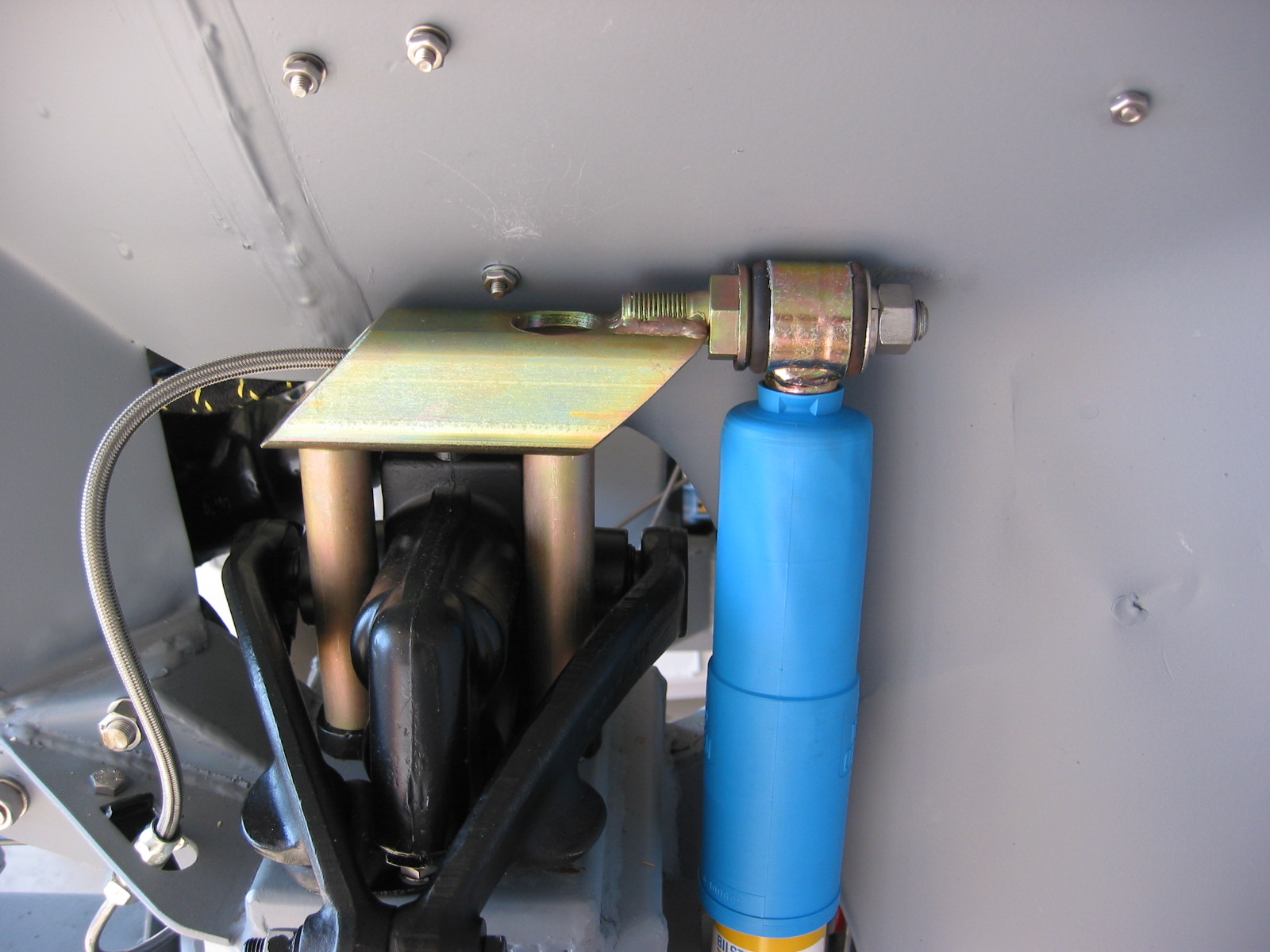
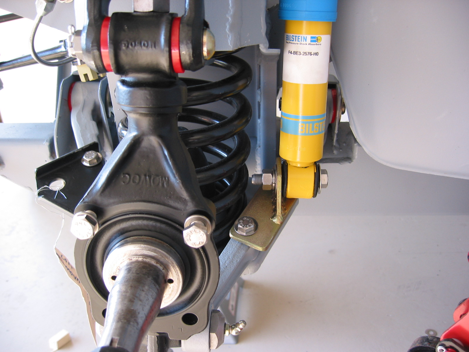
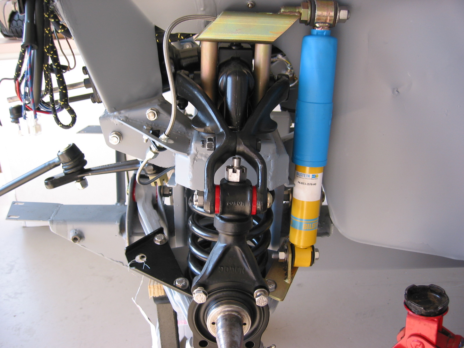
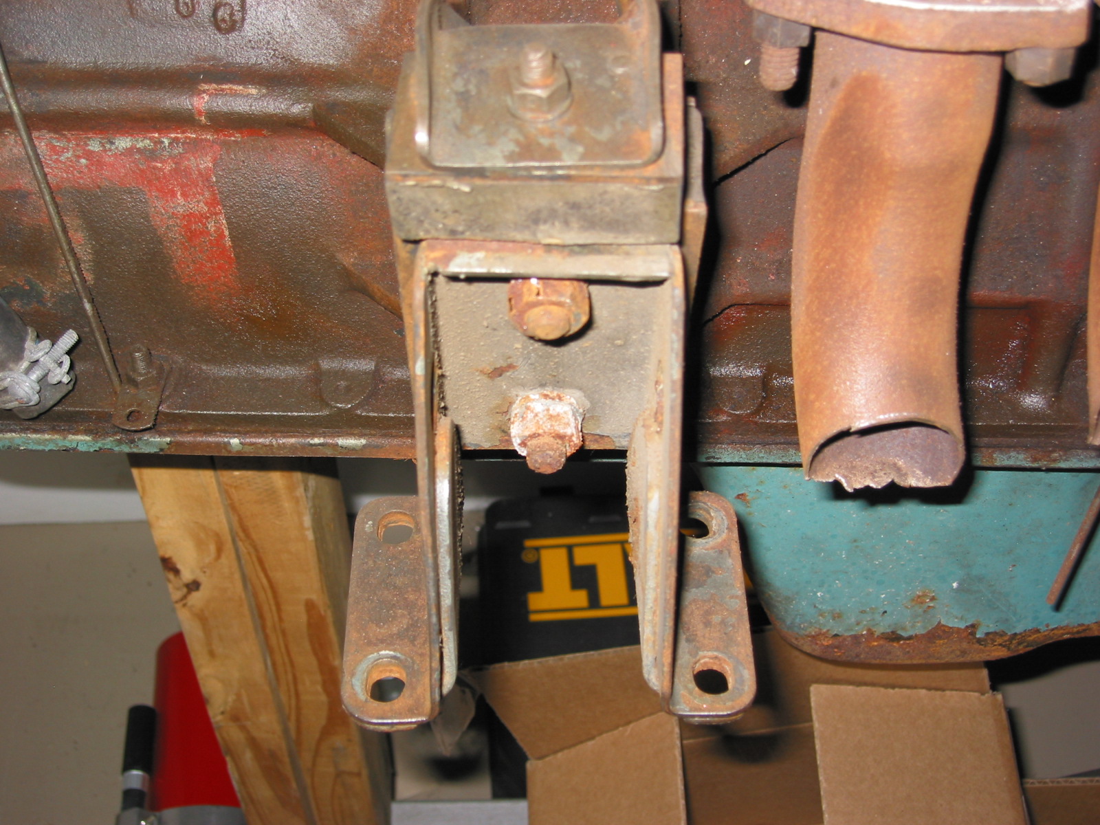
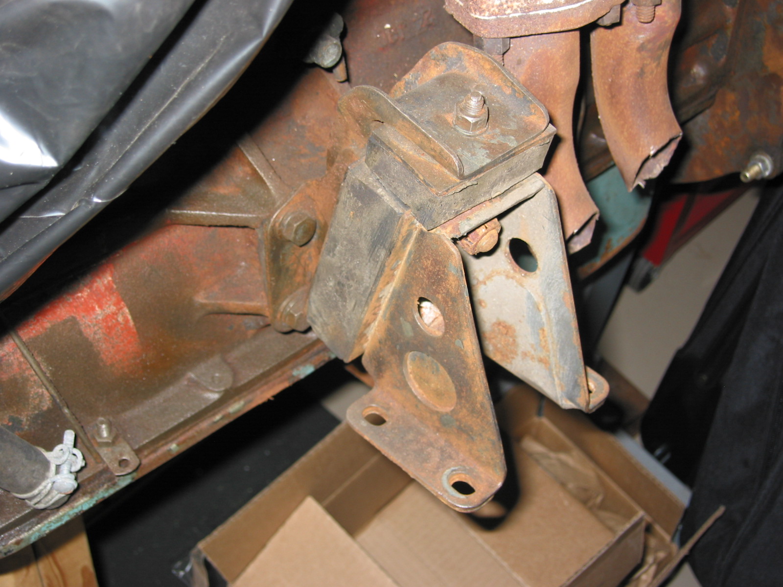
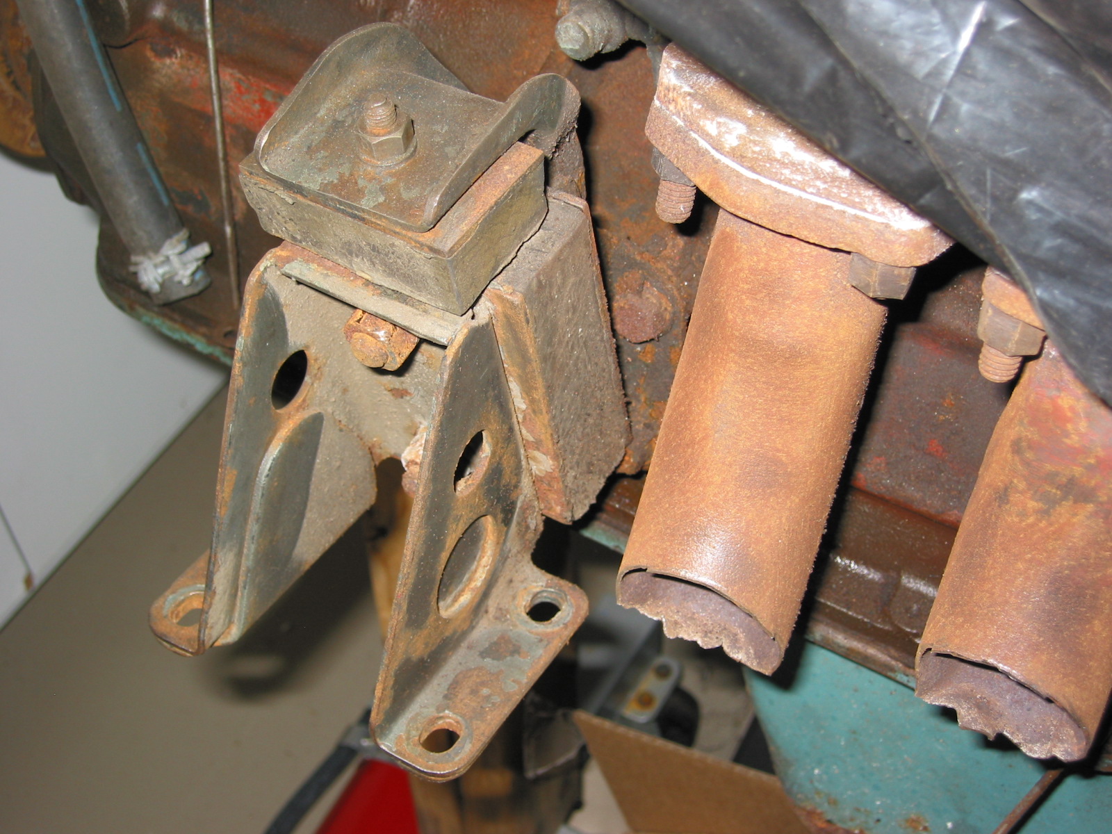
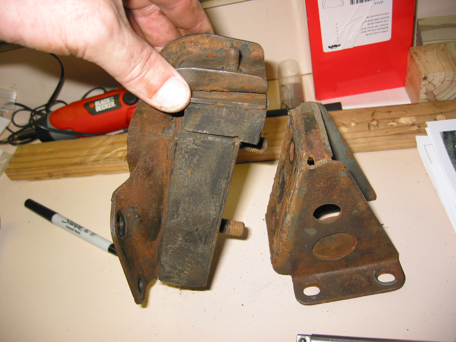
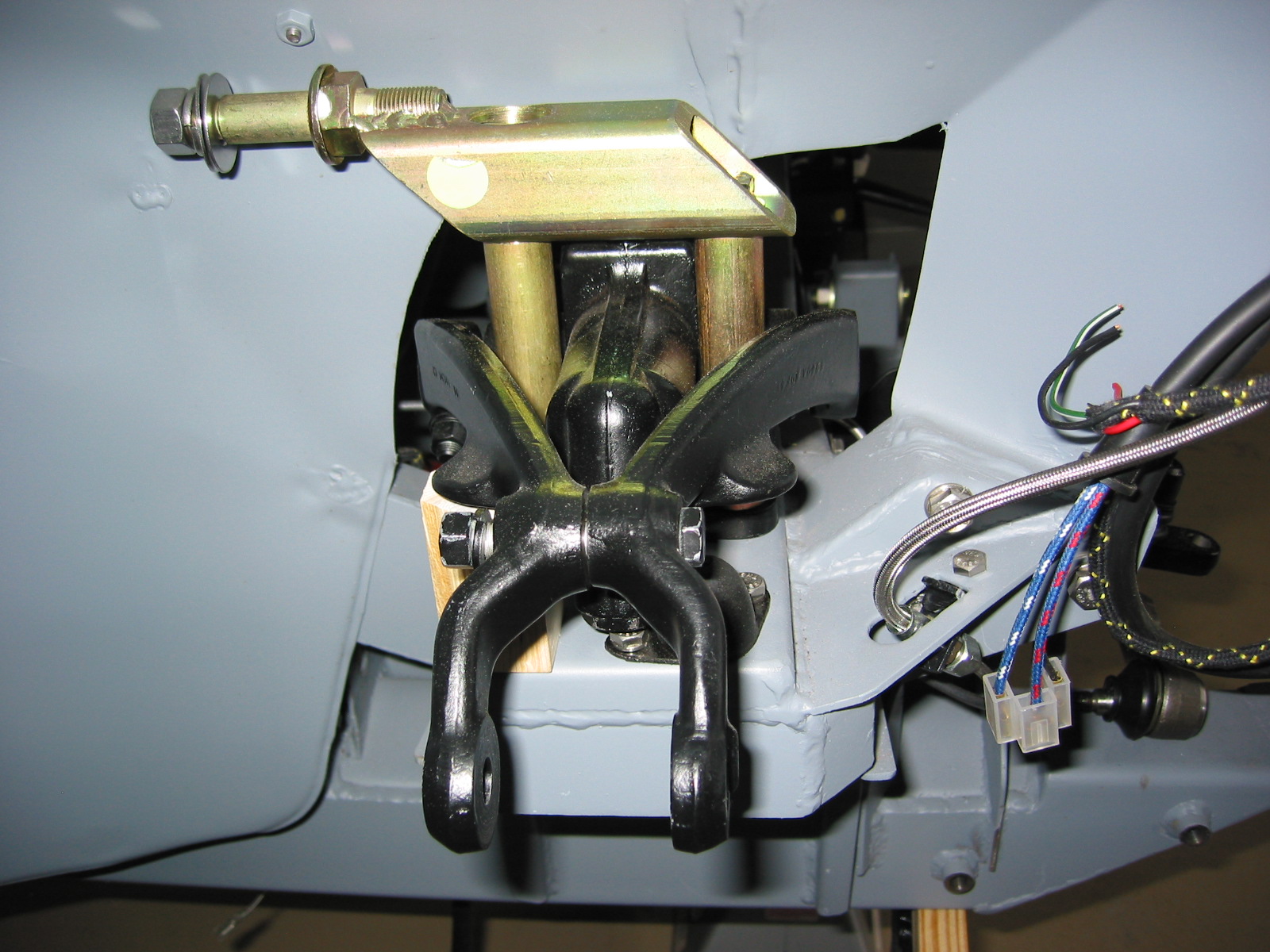
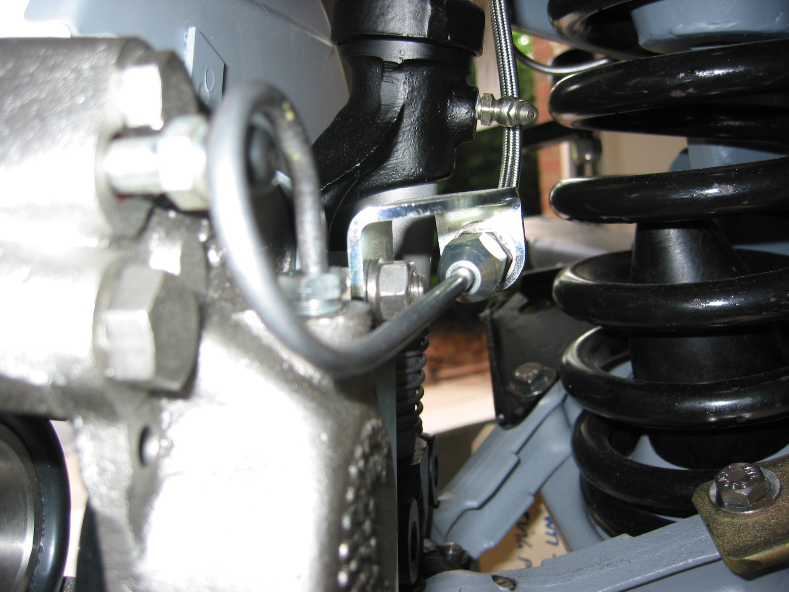
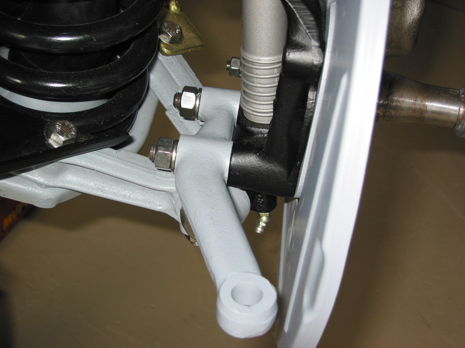
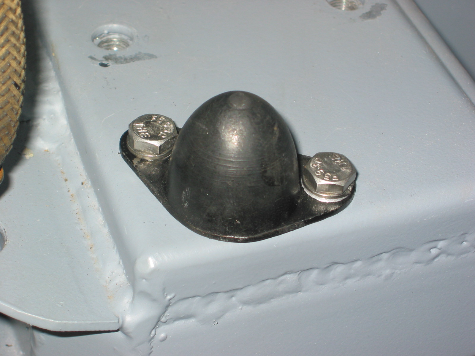
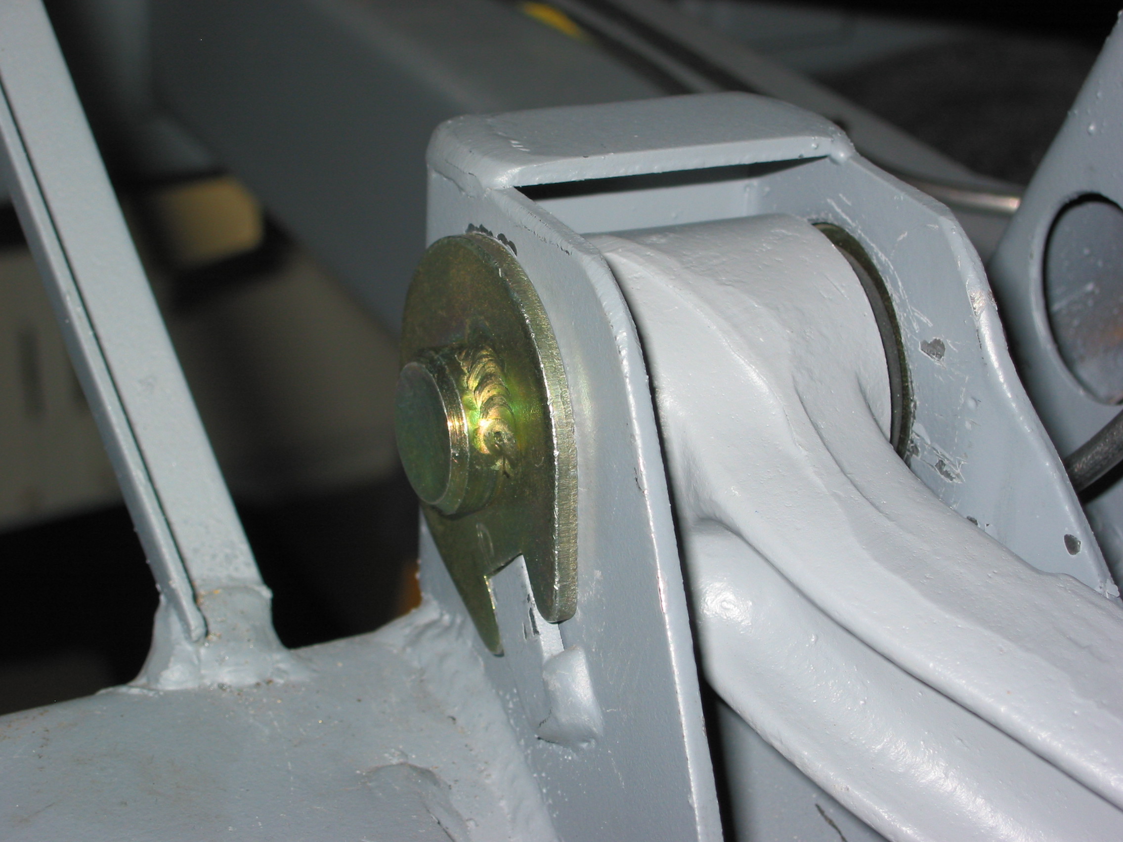
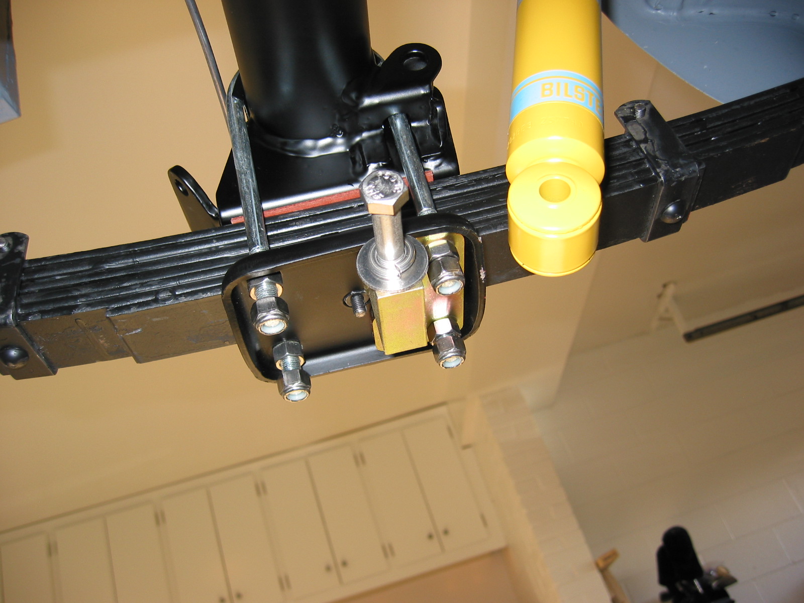
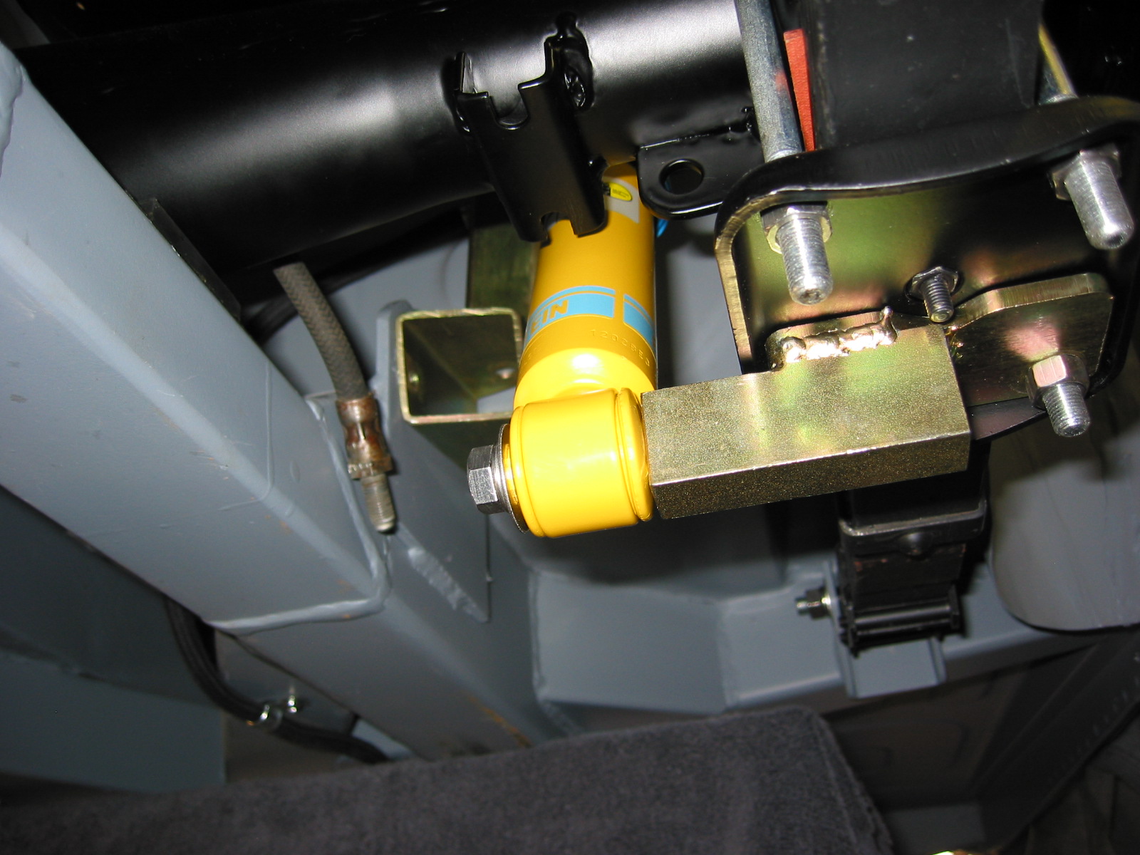
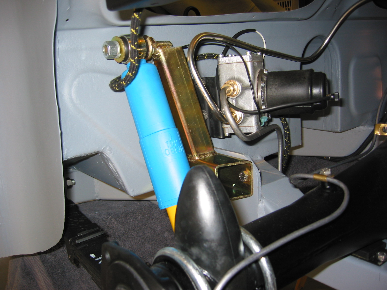
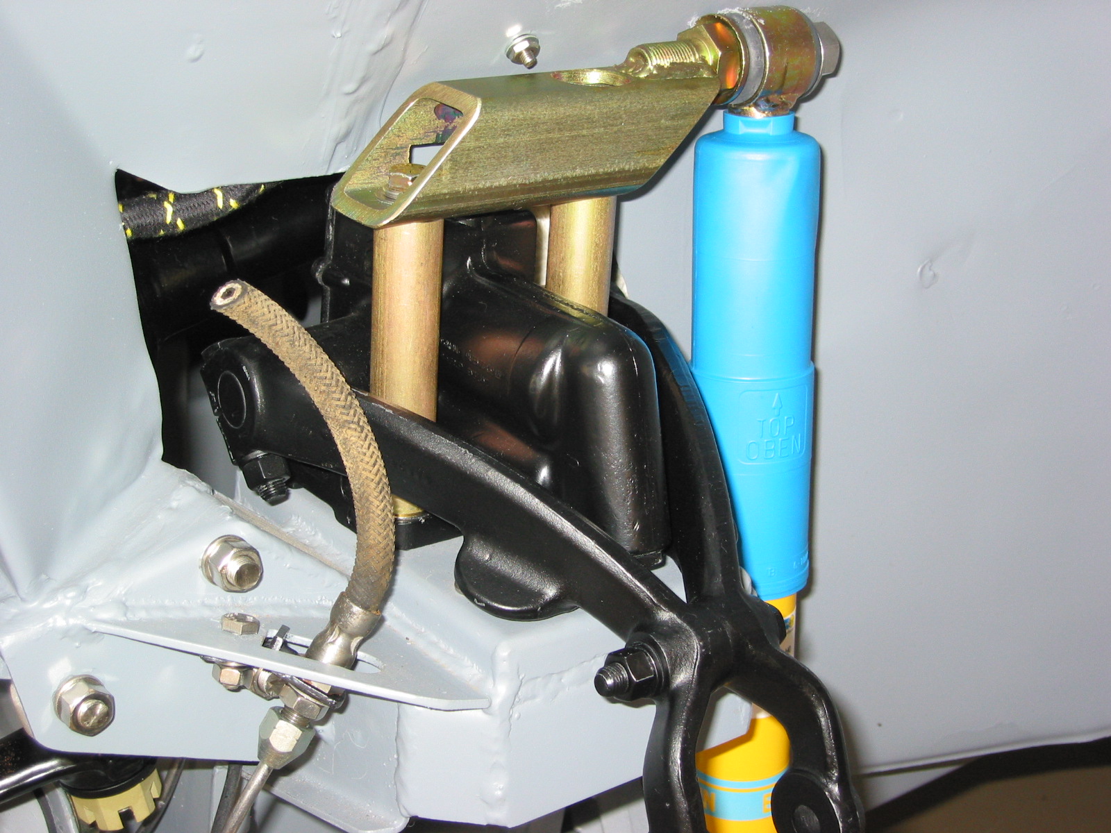
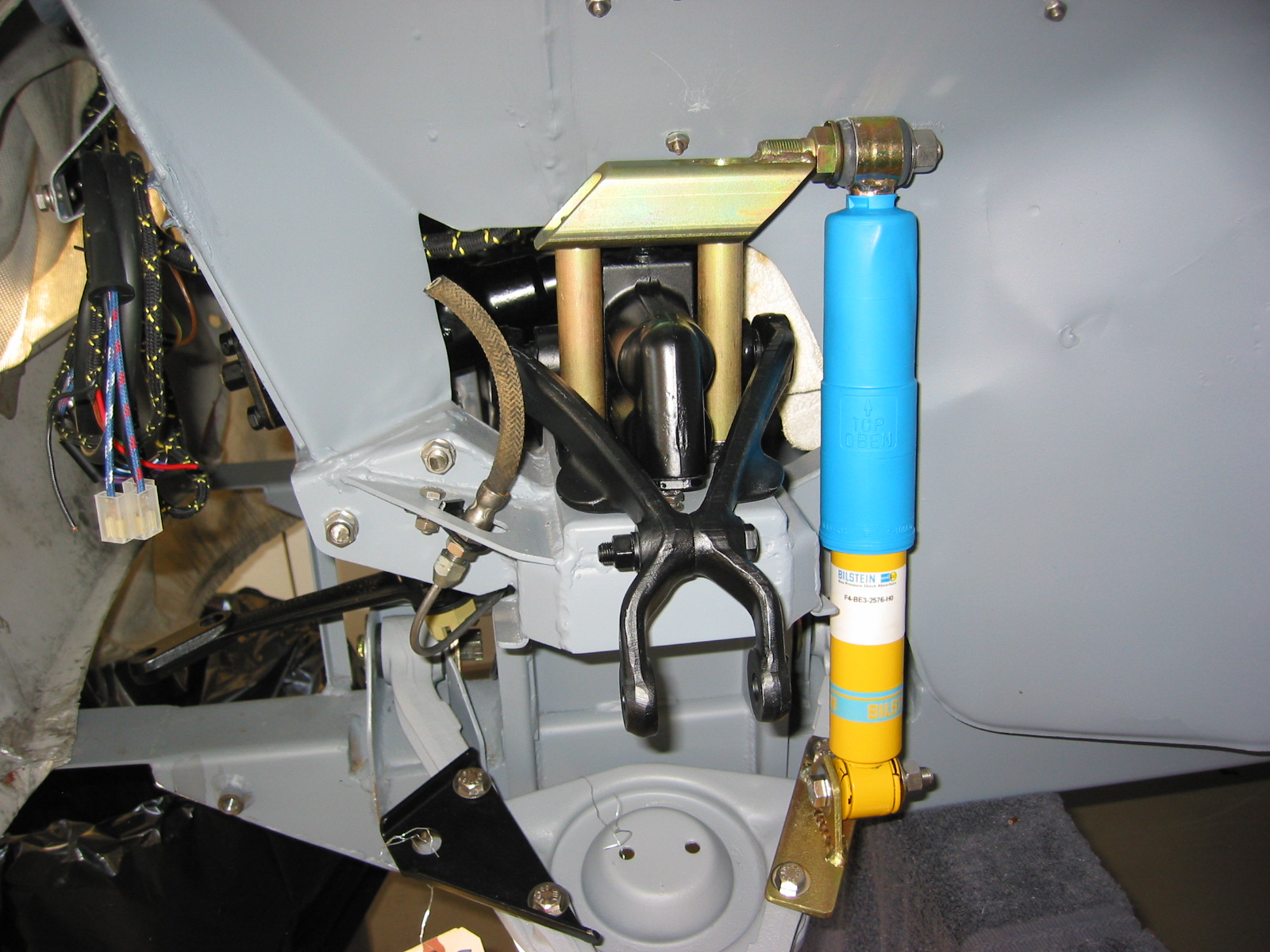
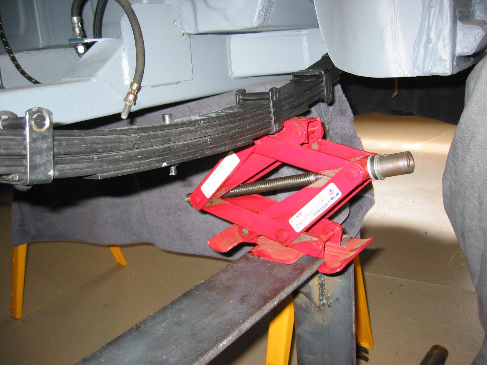
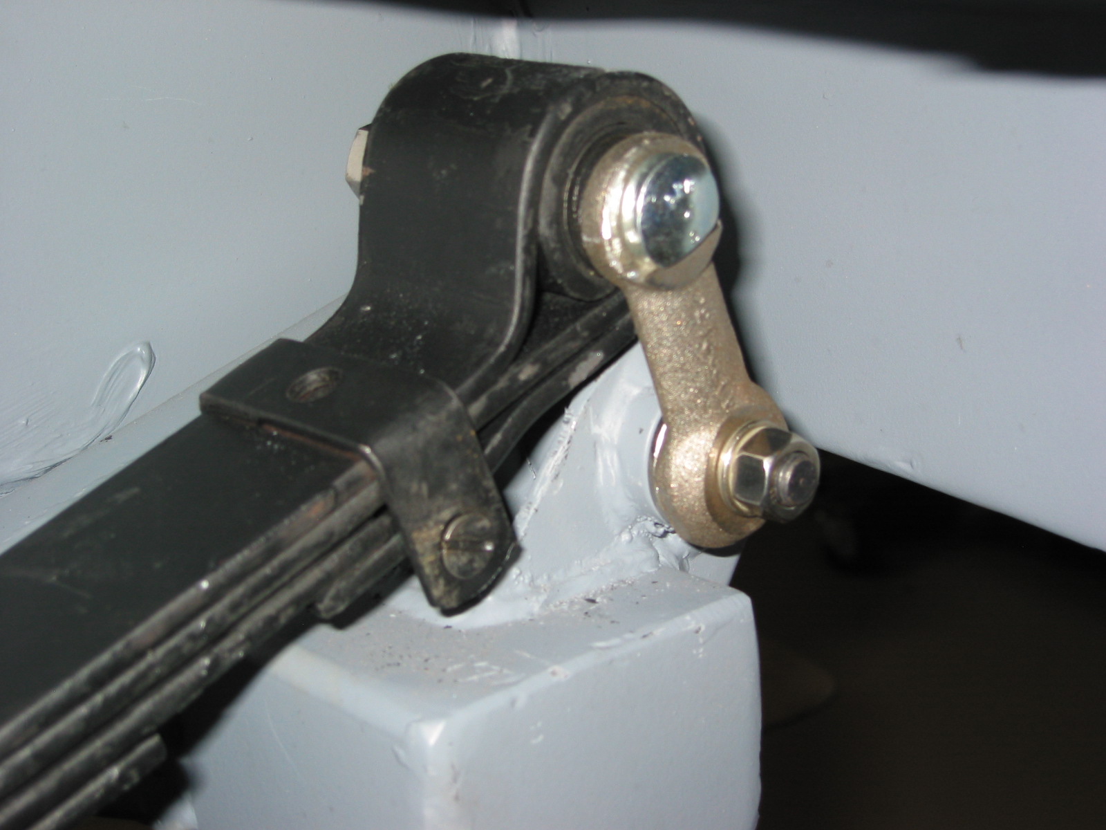
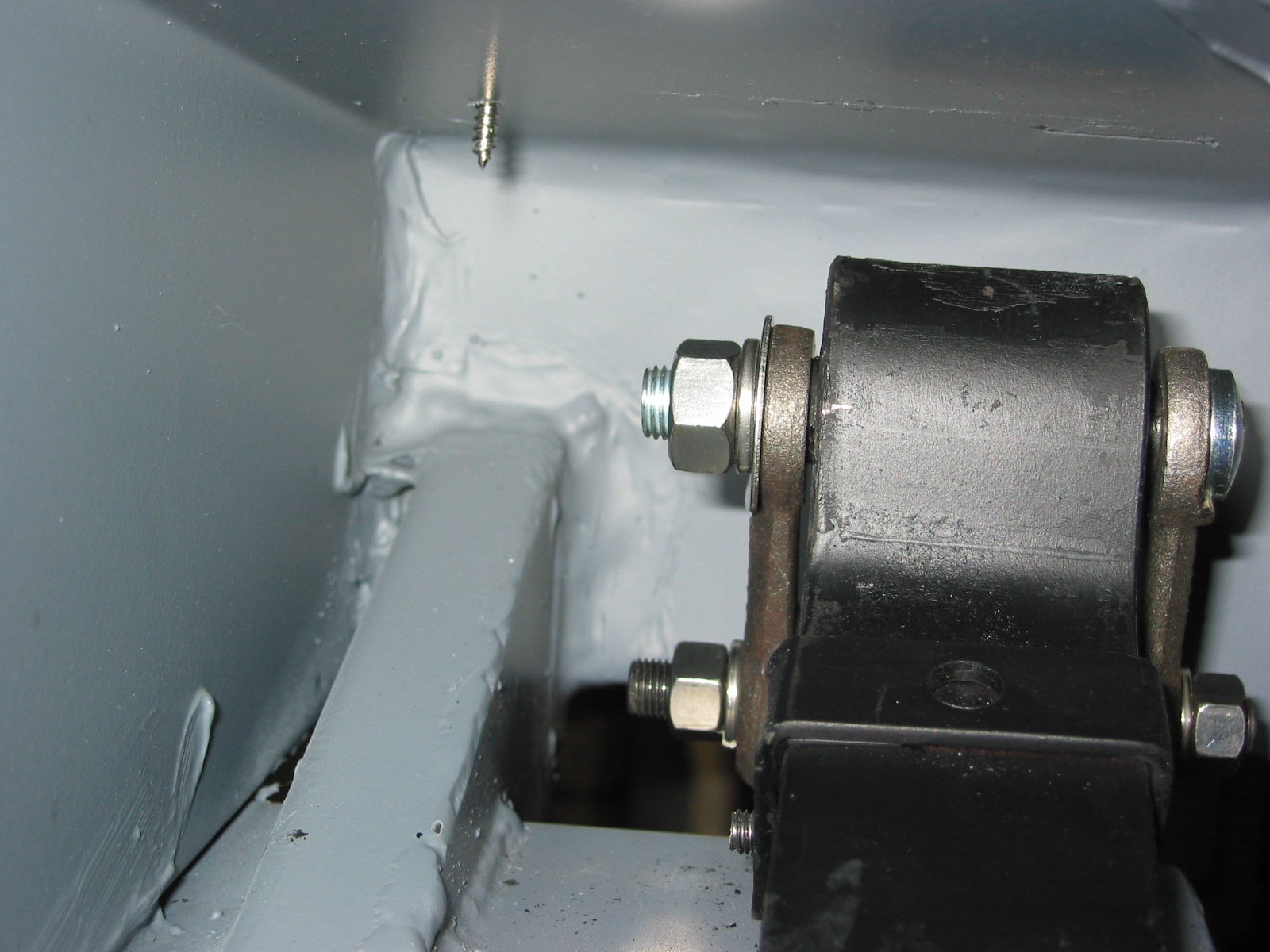
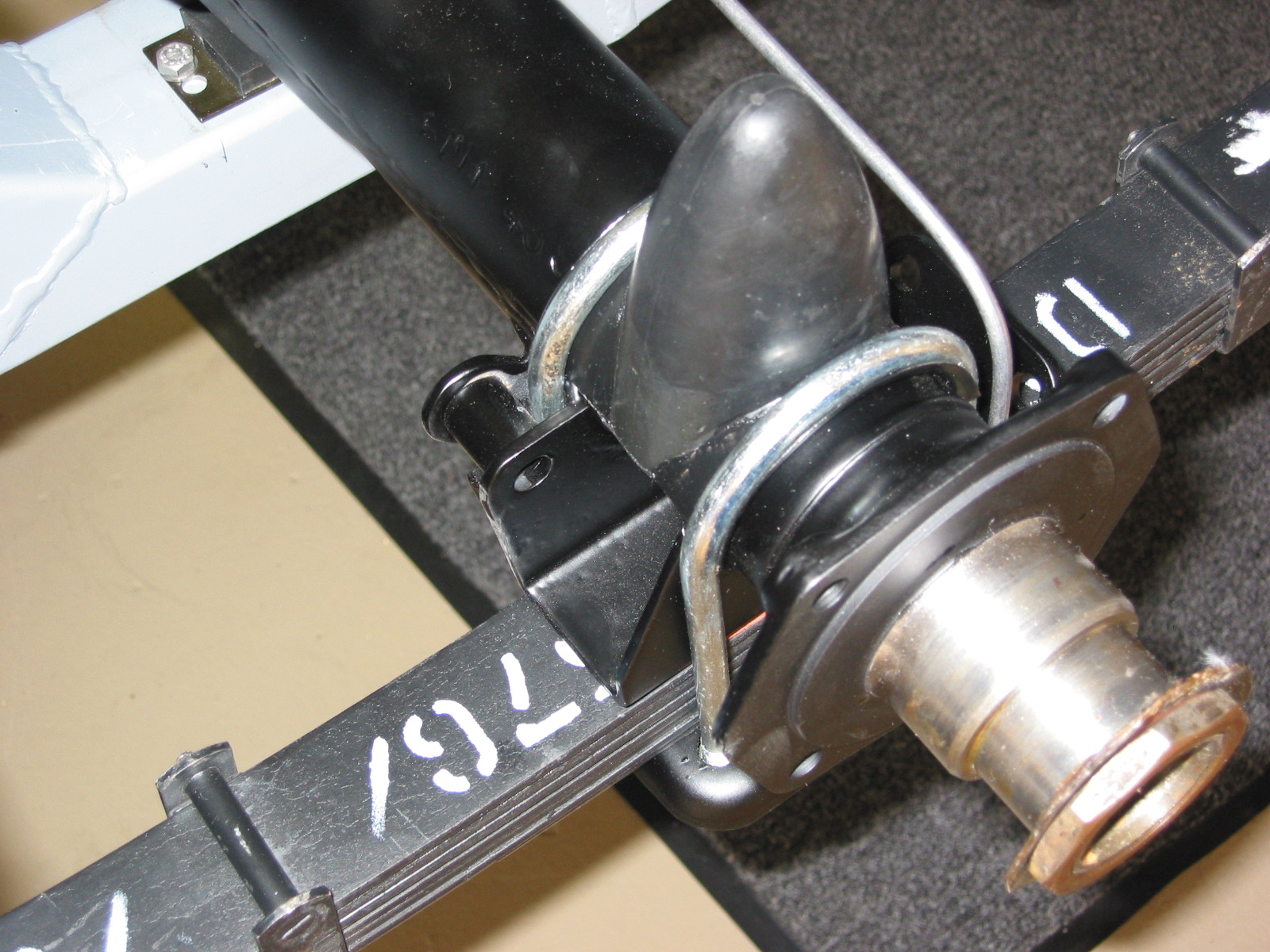
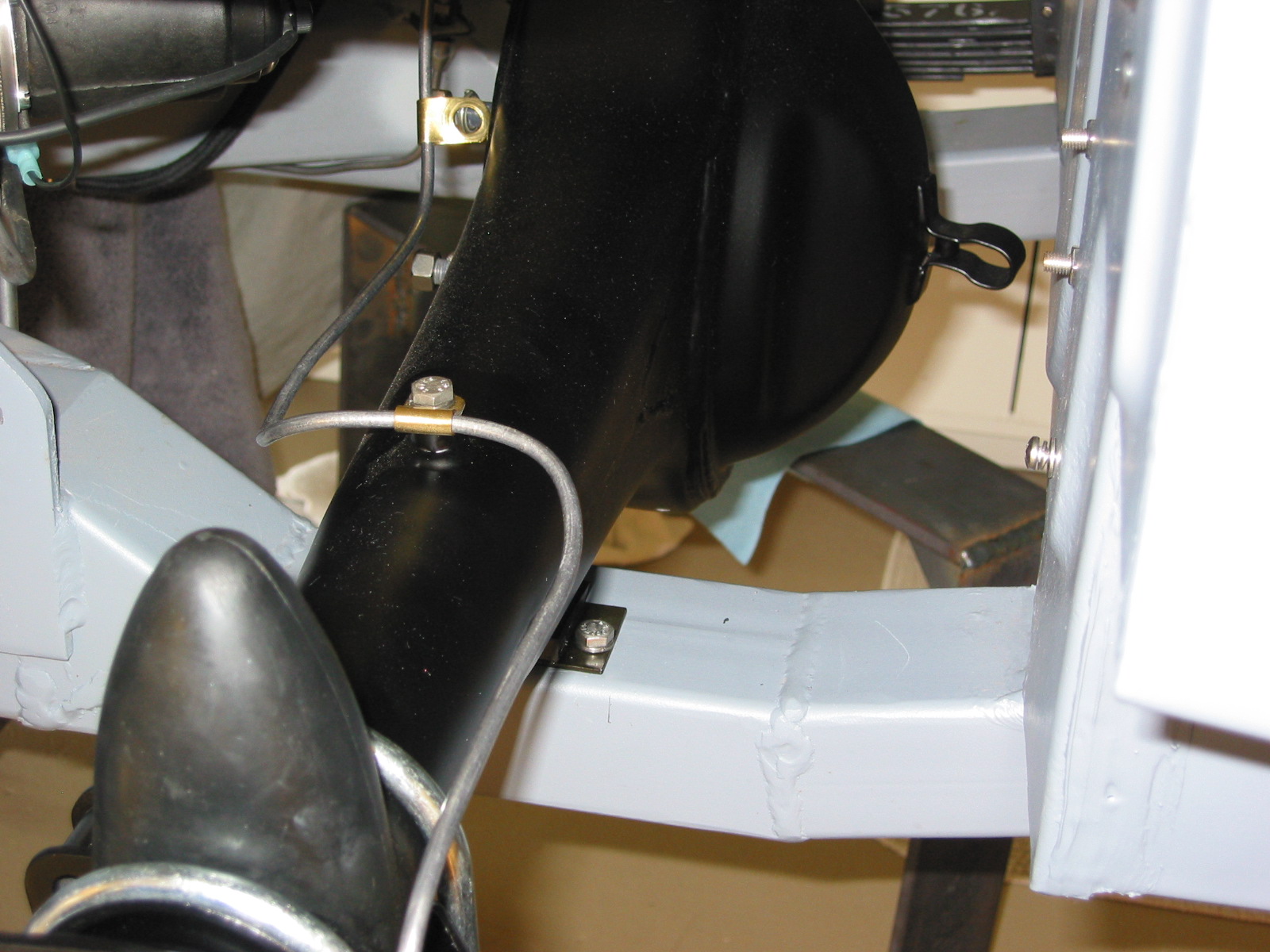
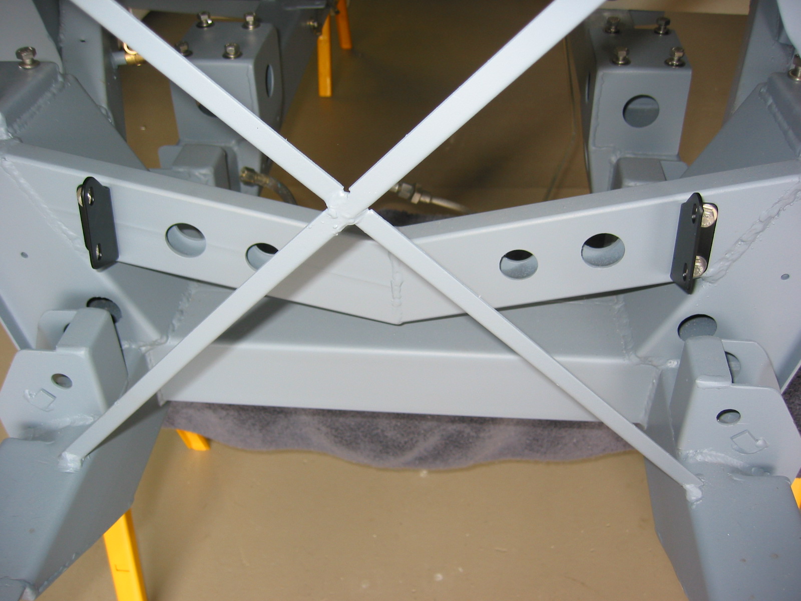
Installing the Rear Axle – After removing the fuel pump and the left bump box we “walked” the axle with the differential into the chassis and superstructure. I may have been able to leave the fuel pump had we had more access room on the right side of the car, but that wasn’t available. I then secured the axle with the Ubolts and the brackets for the tube shocks. The key here is to start each side loosely and then return to fully tighten each side. I never could get the tube shocks to align with the brackets and Udo Putzke thinks it may be because the Jule frame is slightly different than the original AH frame. To his credit he has agreed to make some longer shaft shocks at cost – great customer service!
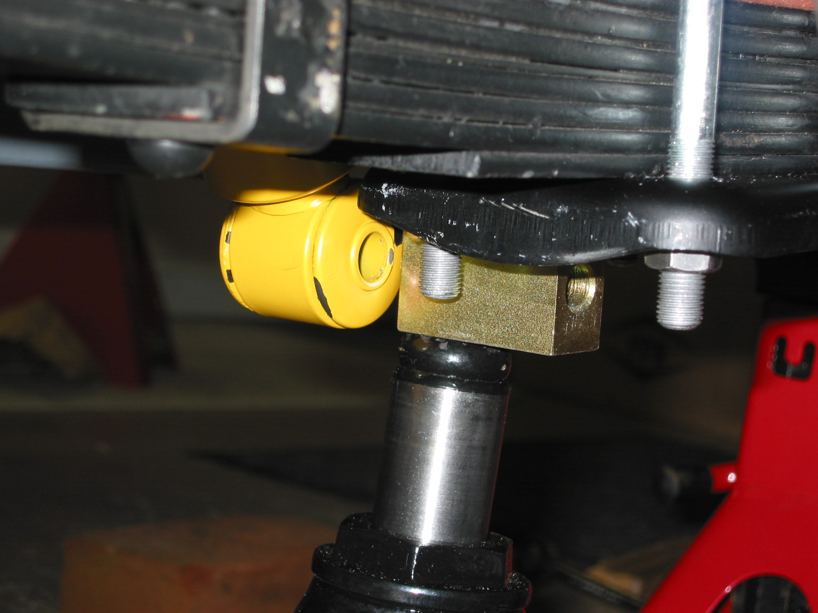
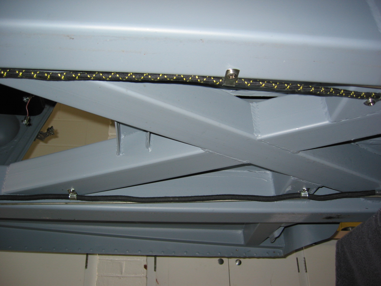
Bilsteins won’t align
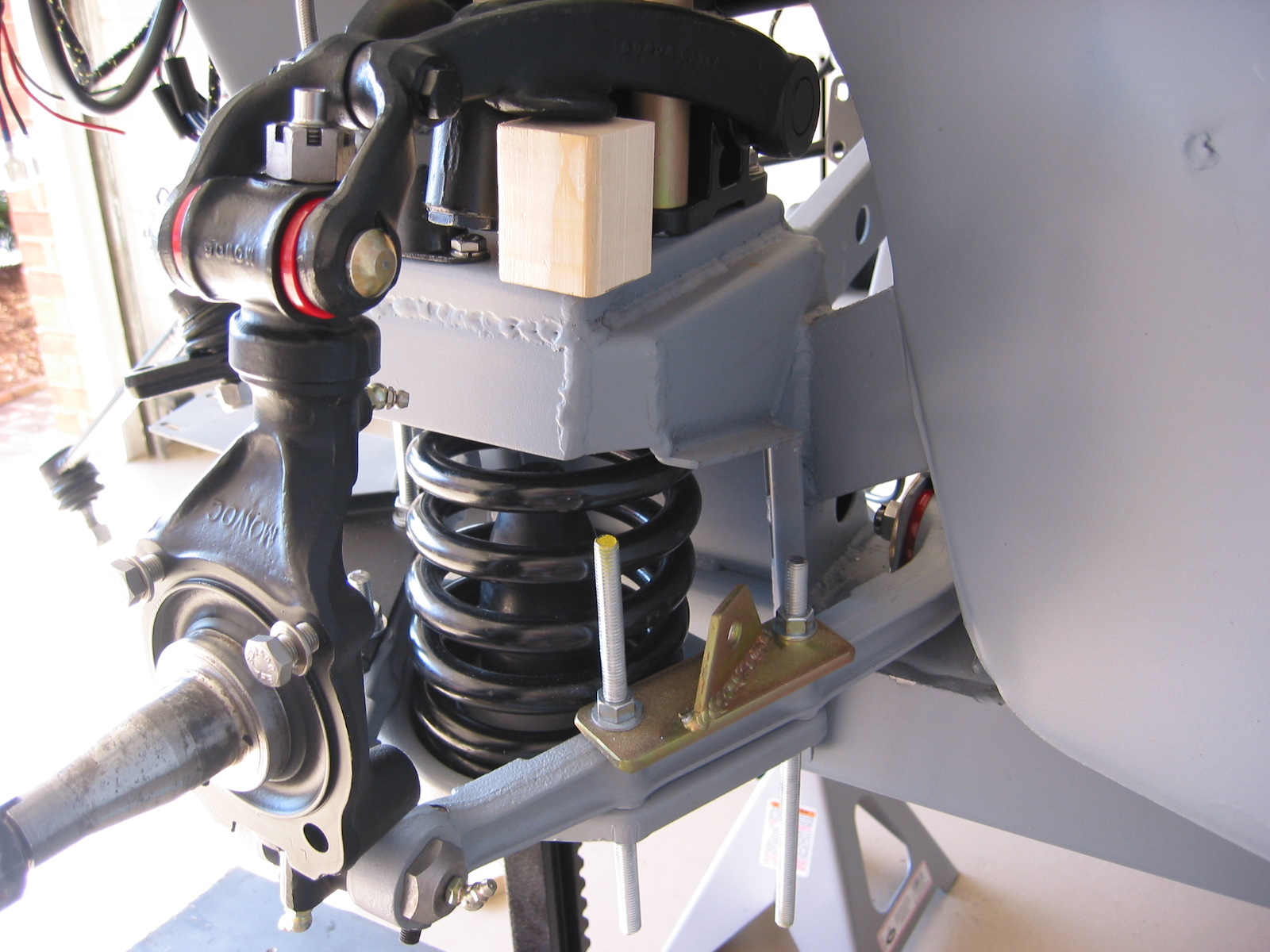
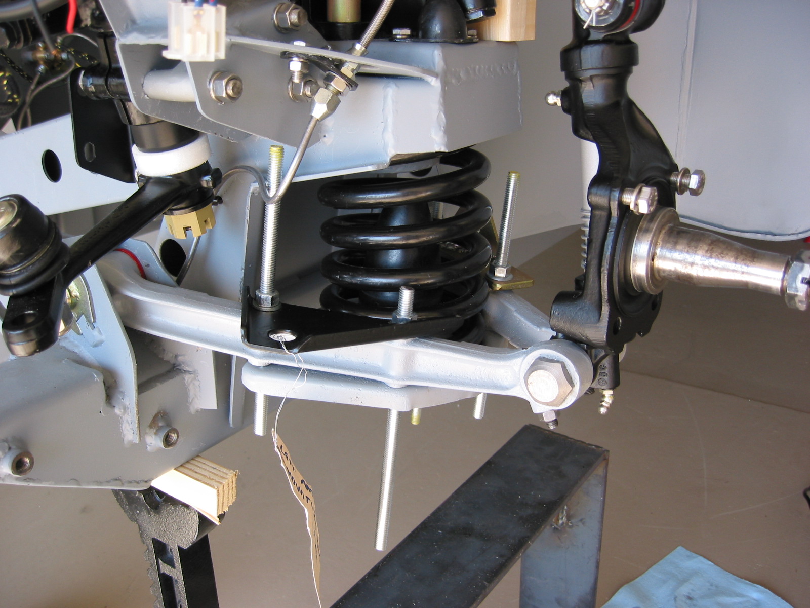
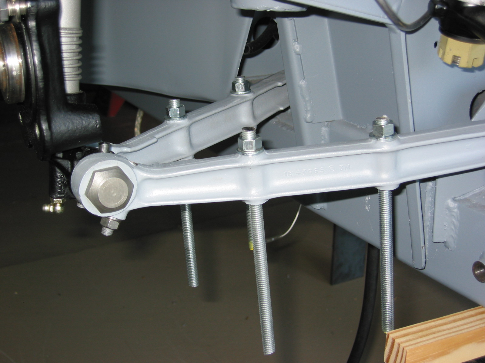
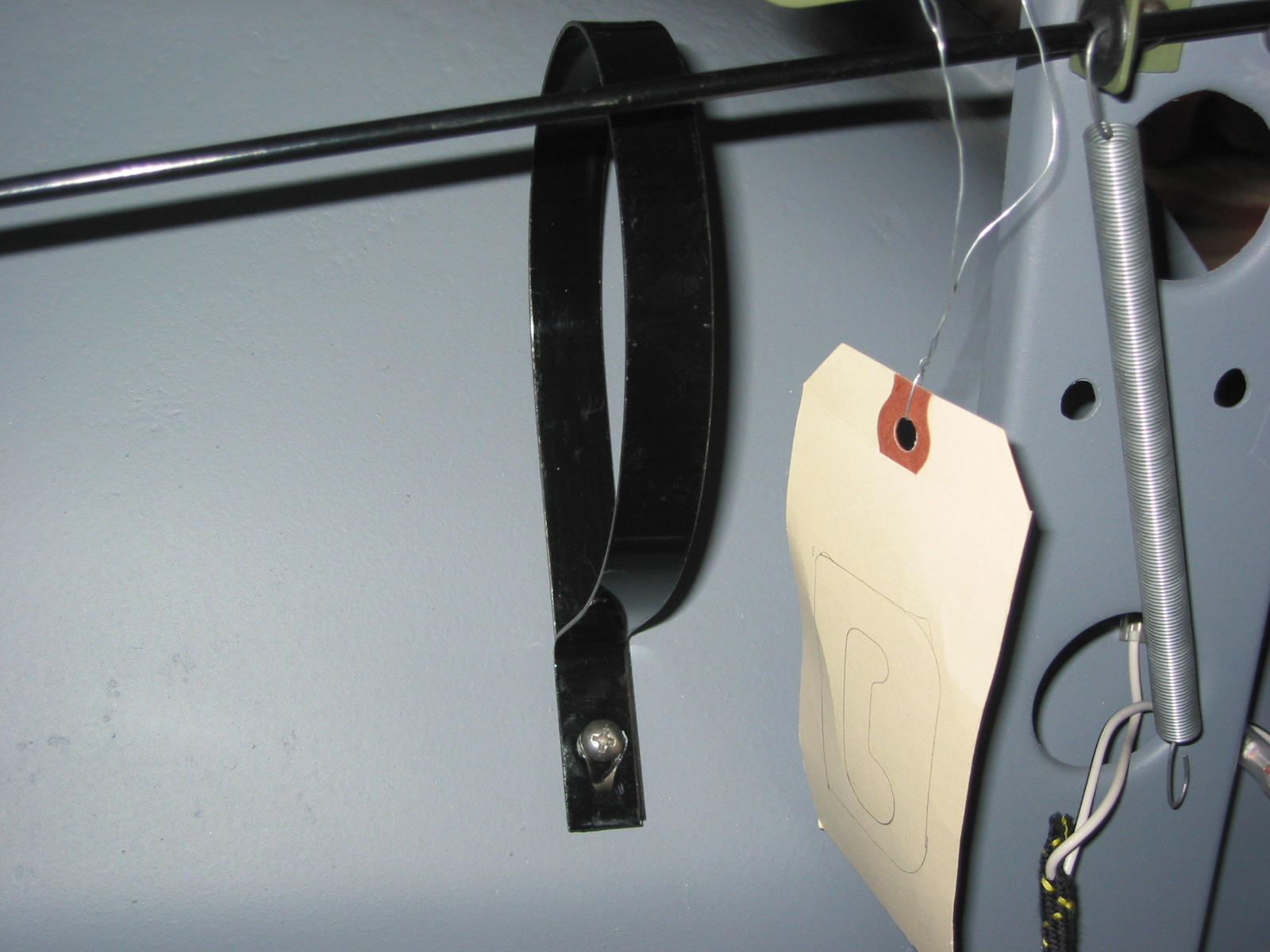
Spring Work
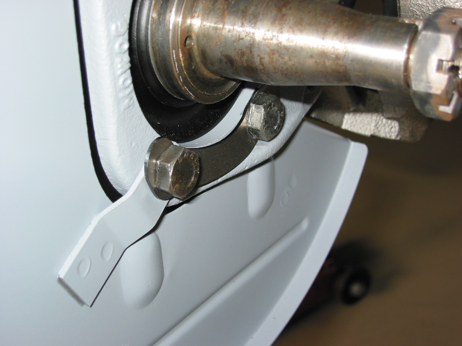
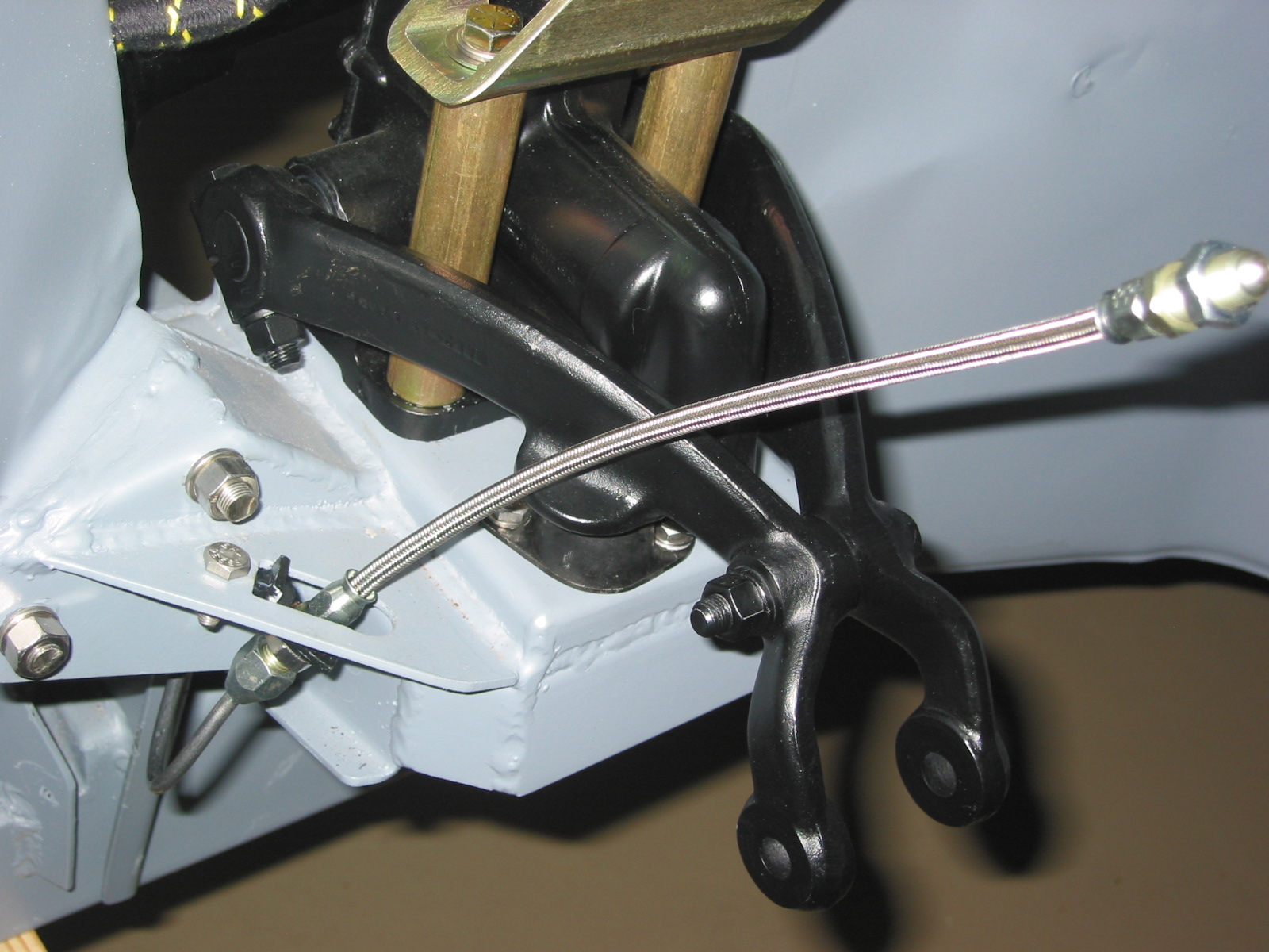
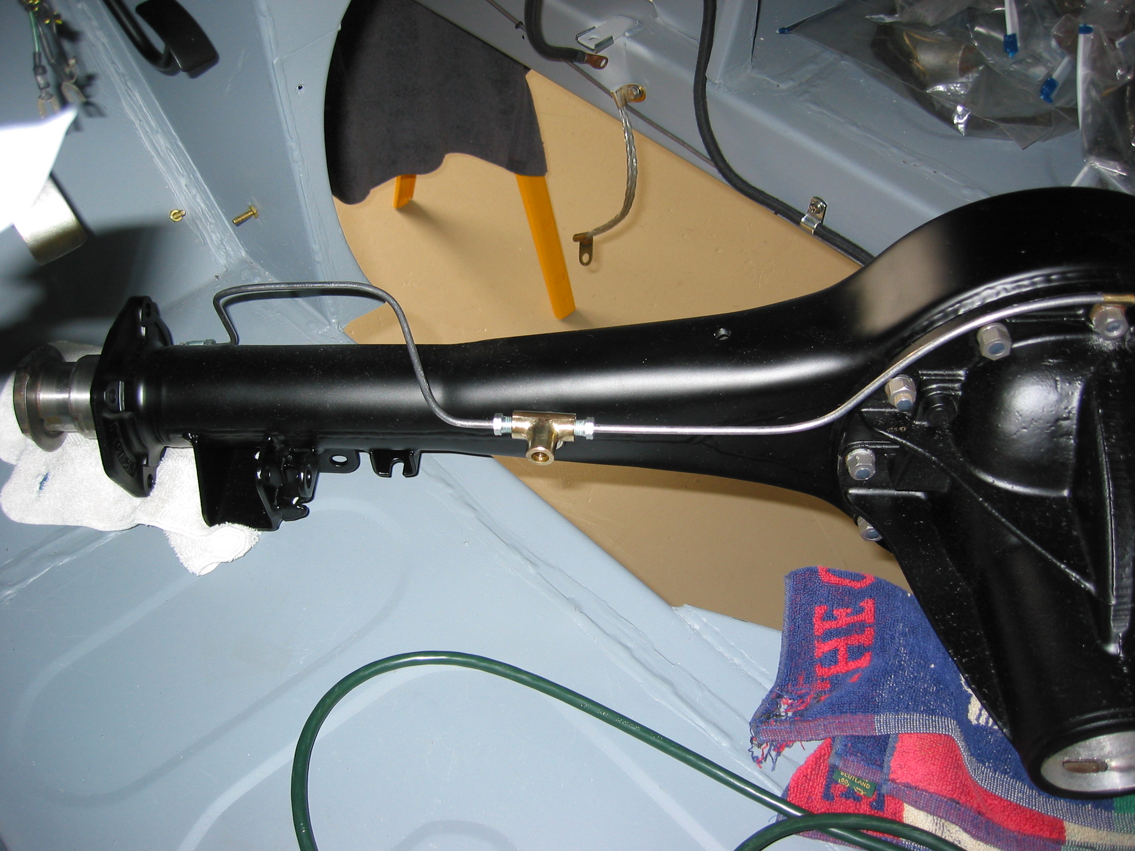
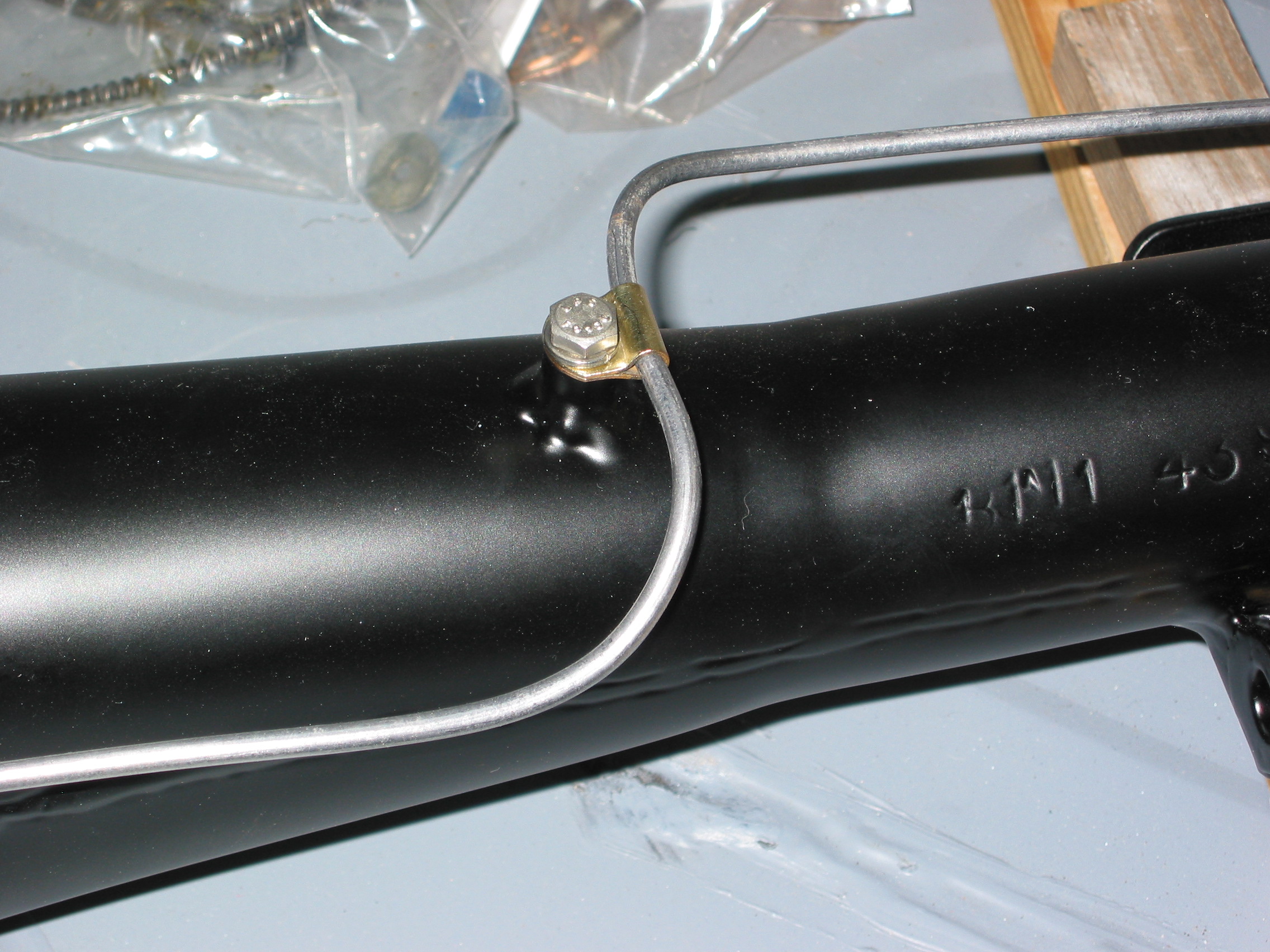
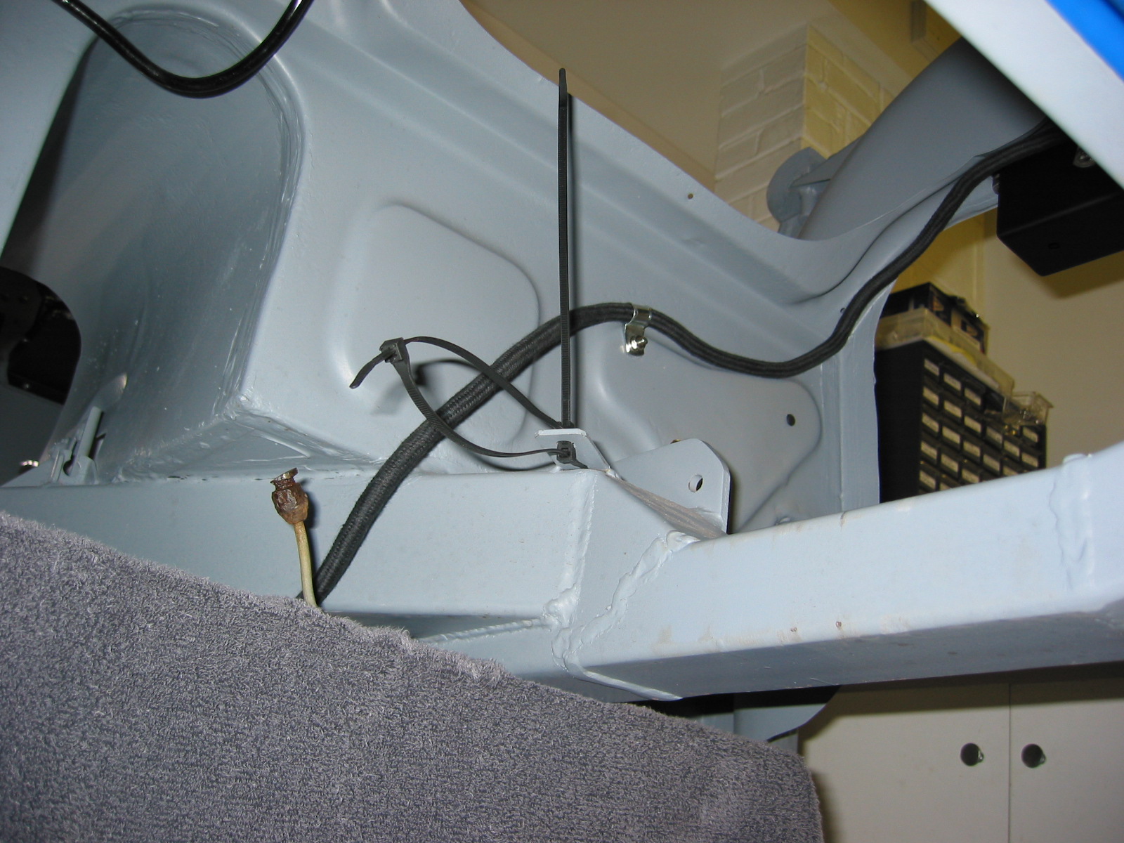
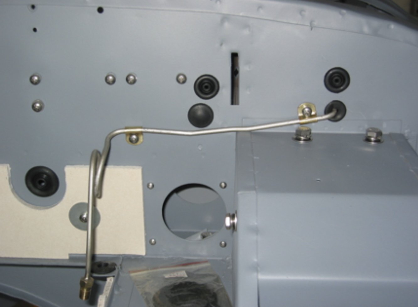
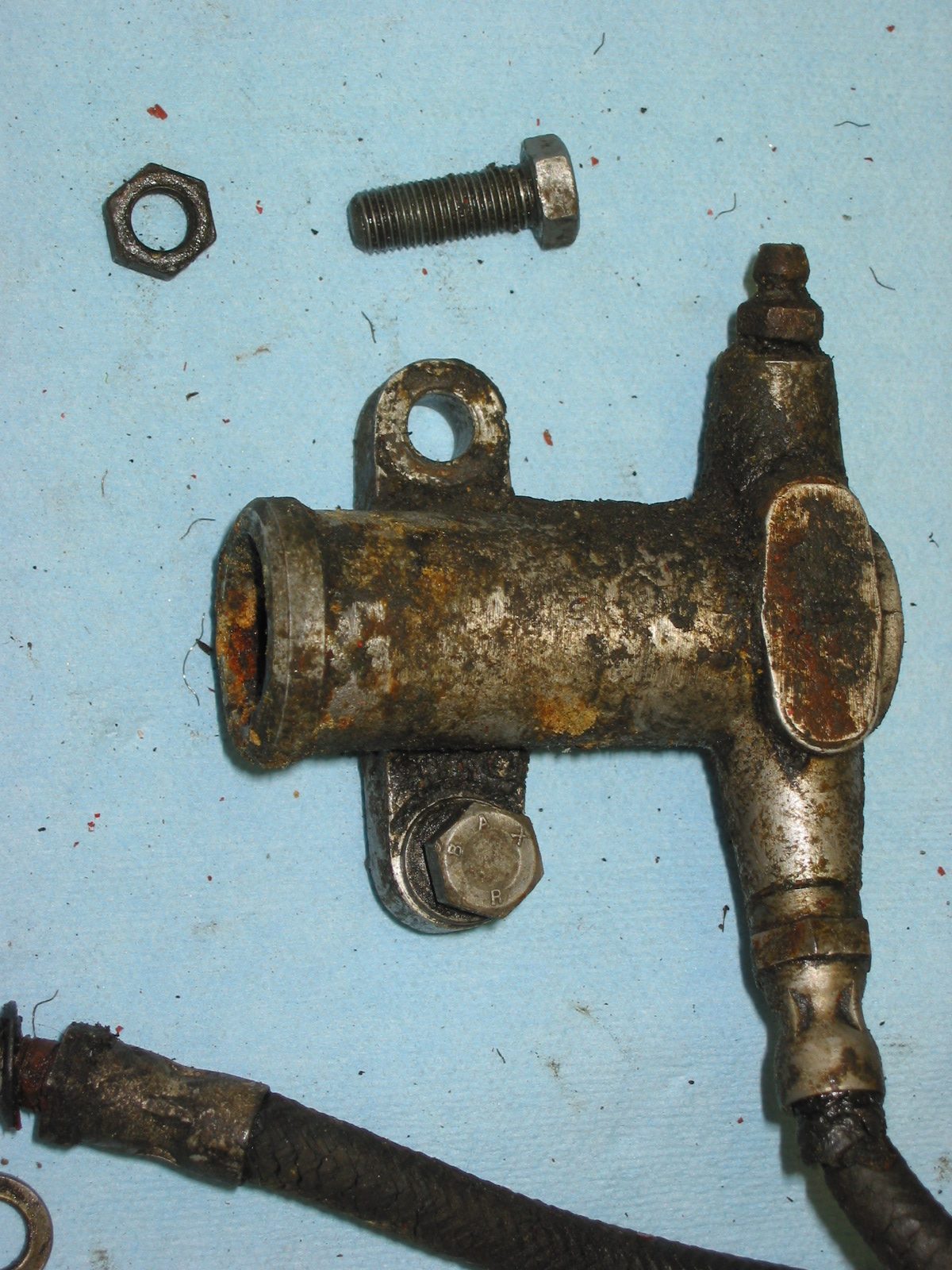
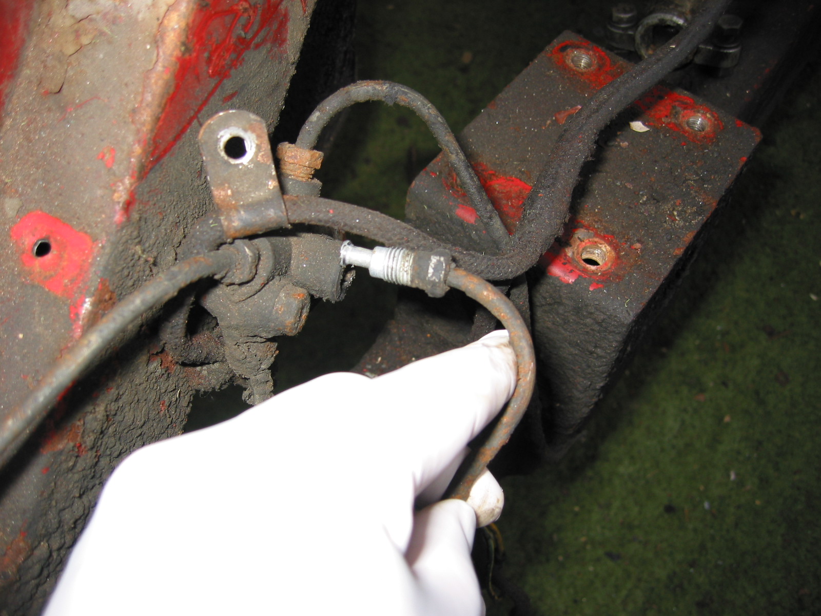
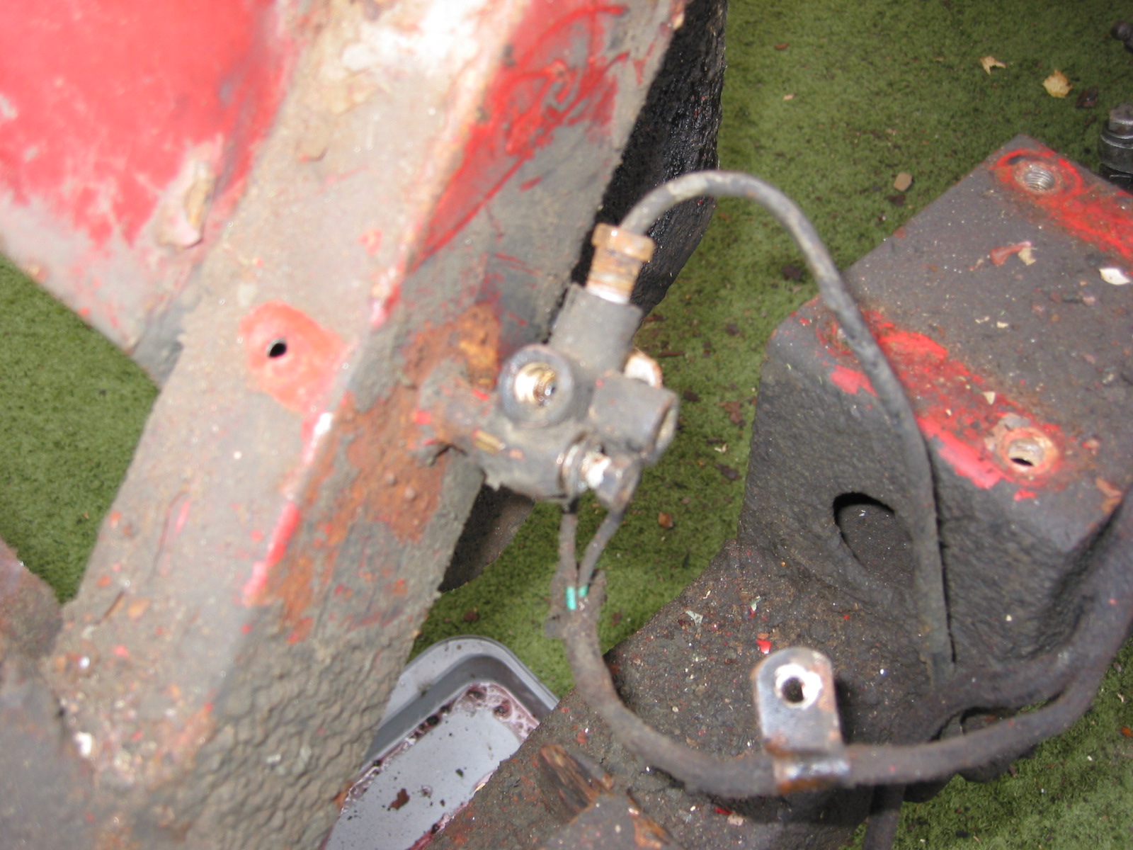
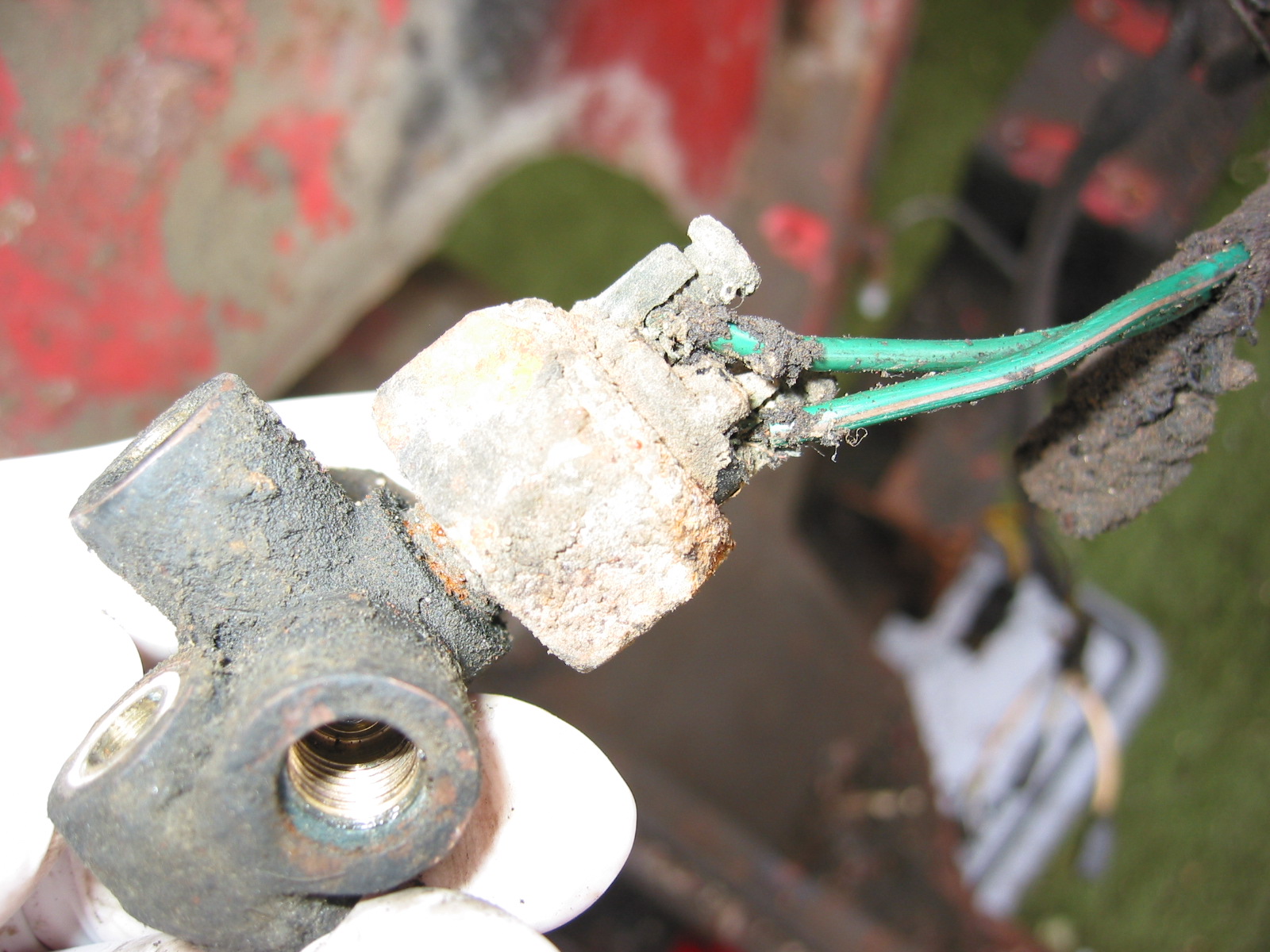
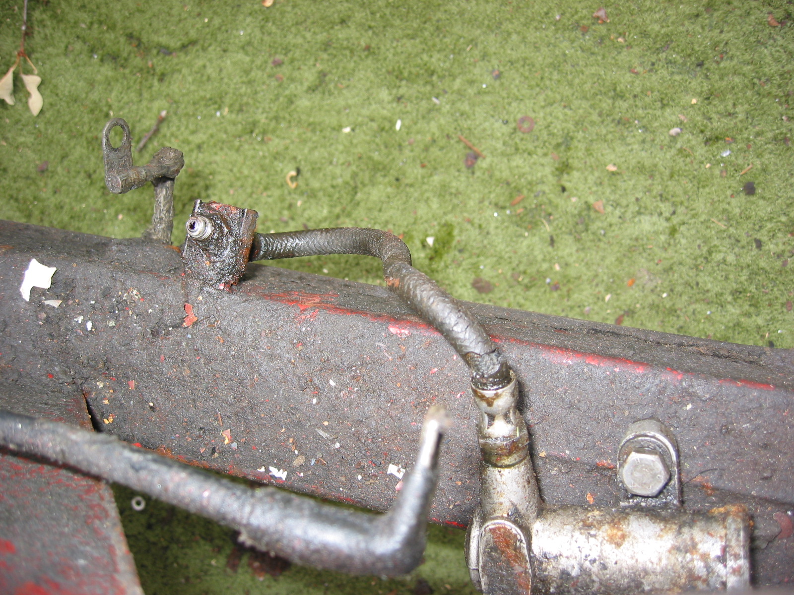
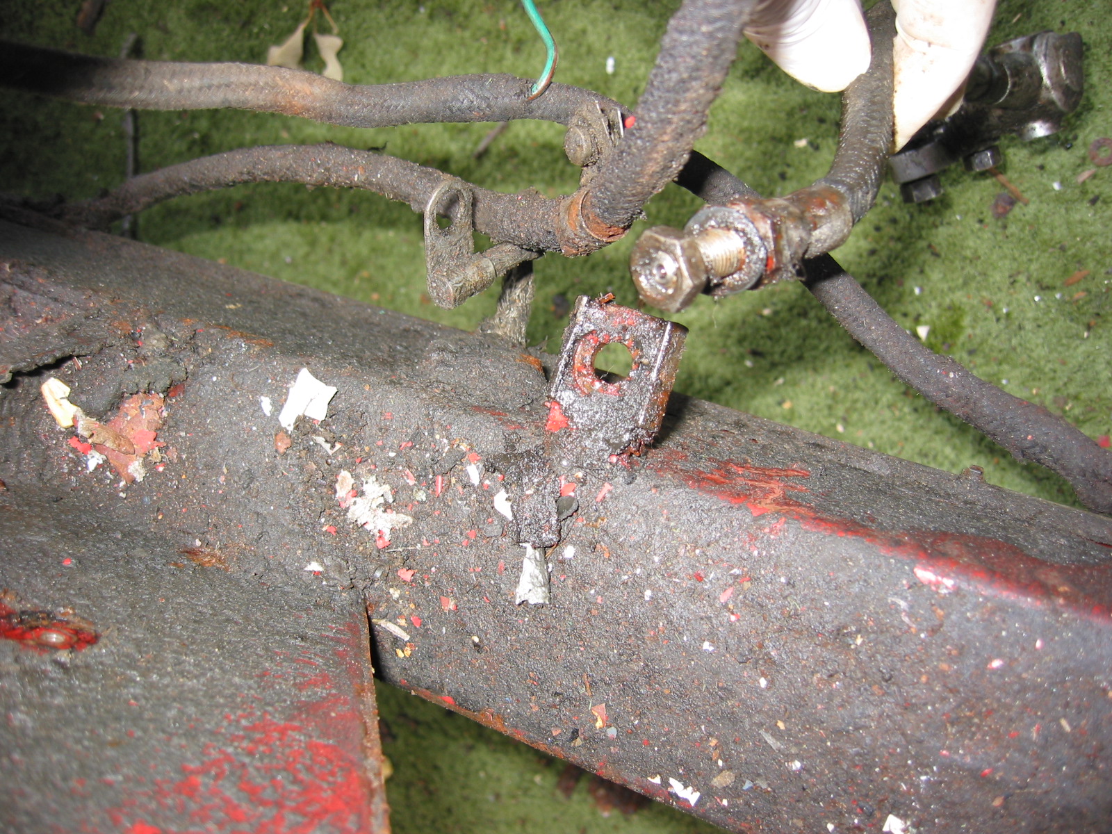
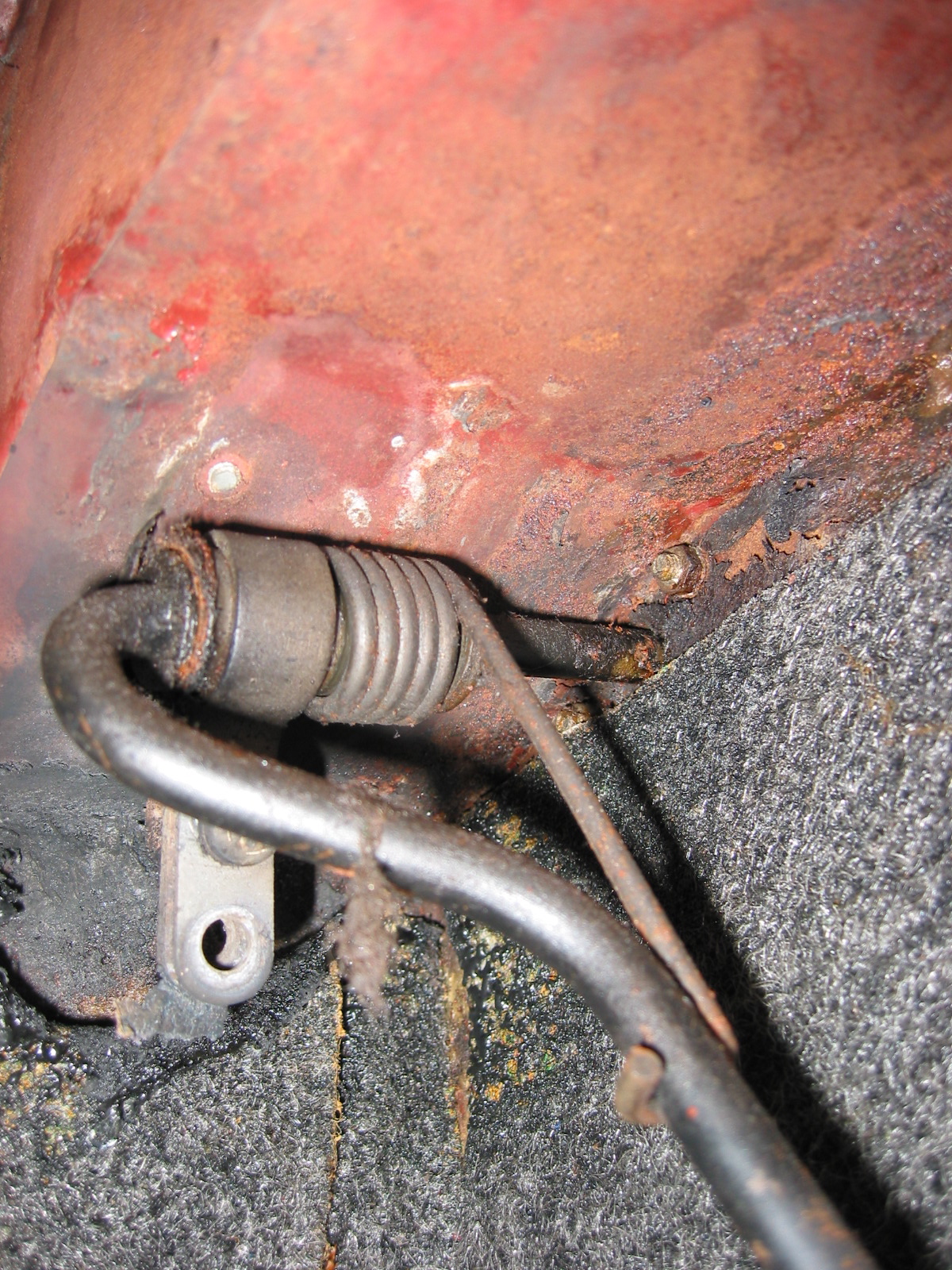
Rear Brake Hose – Added the new stainless braided brake hose between the brake line and the rear junction on the axle.
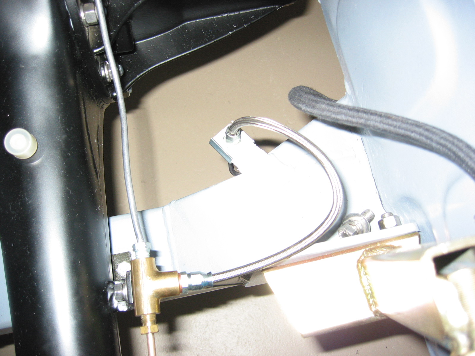
Stainless Rear Brake line
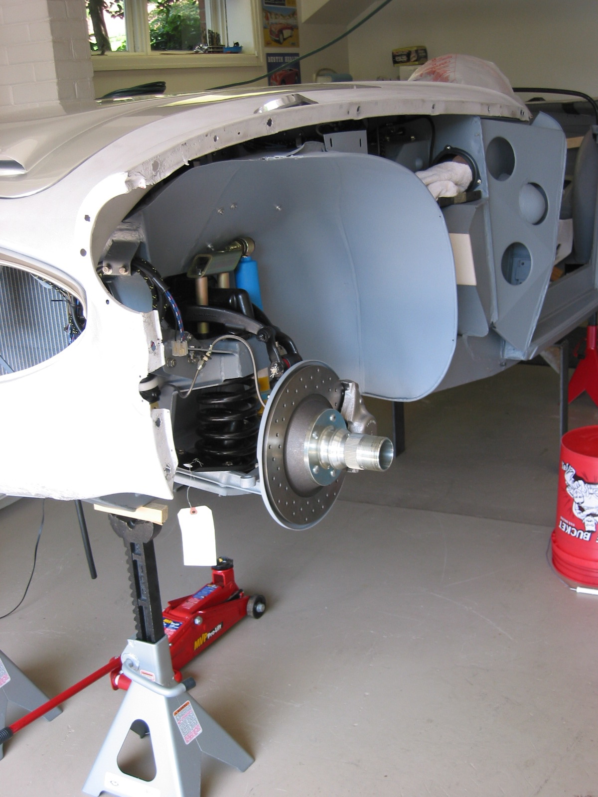
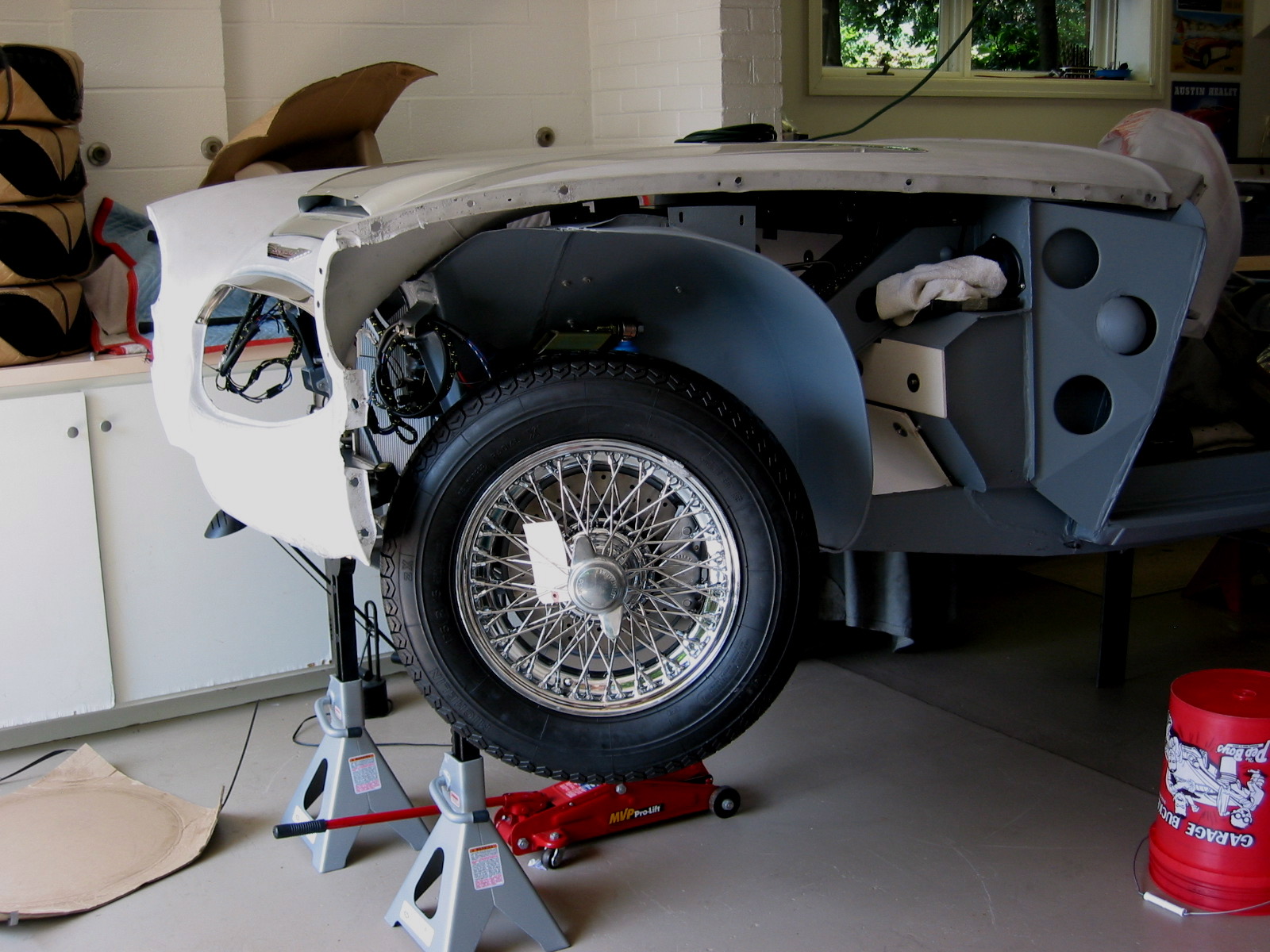
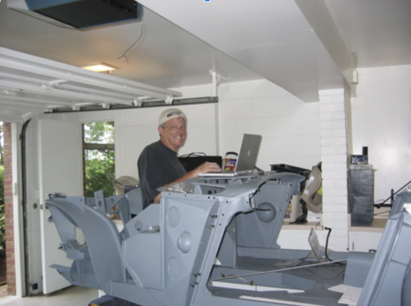
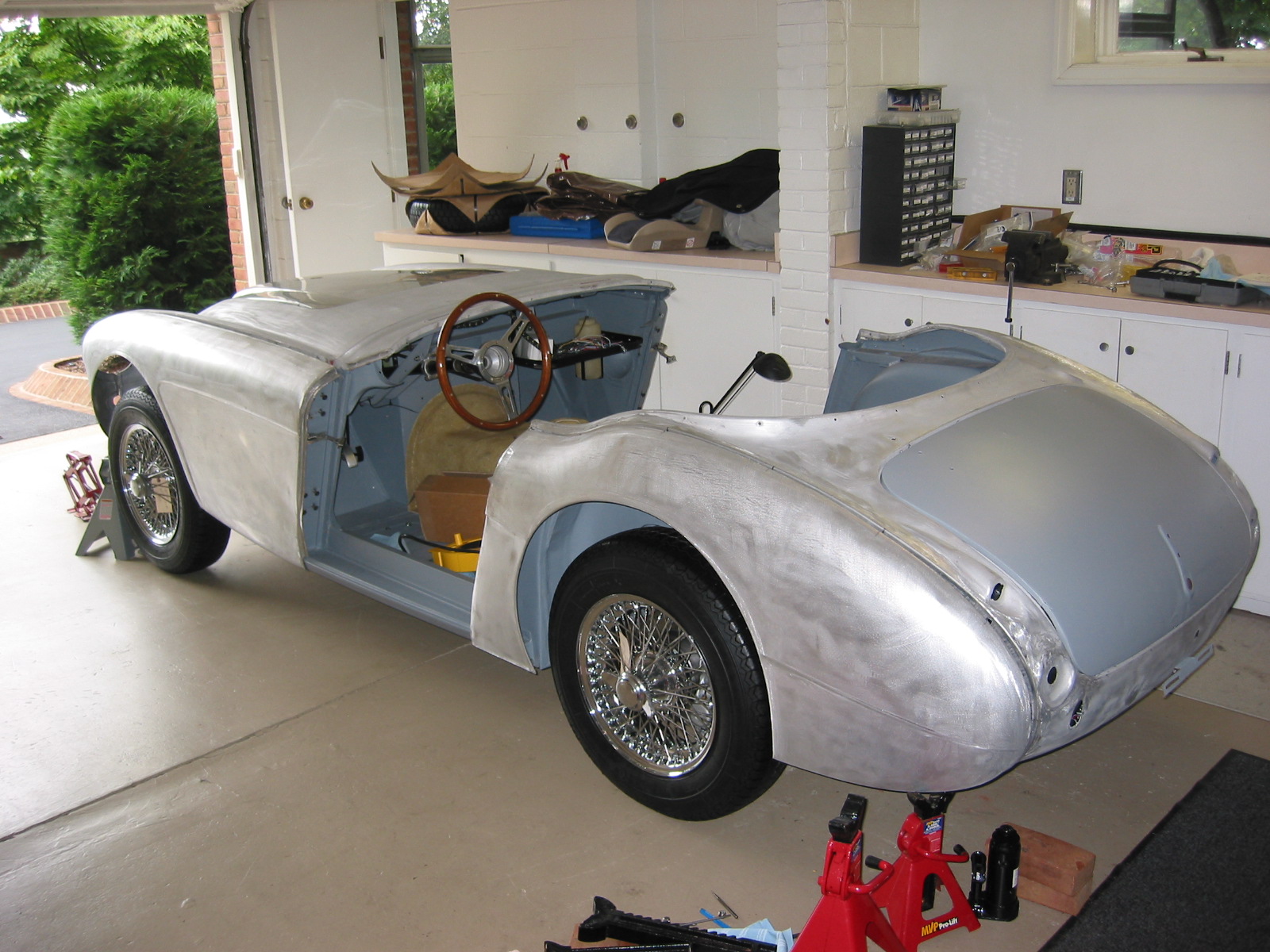
This work allowed me to put the car on the ground as a rolling chassis for the first time – a significant milestone. In honor of the occasion I stuck on two fenders and placed a seat in the interior for photos. All just for fun. It lasted ten minutes and then off came the wheels/tires and wings and then back up on jack stands for more work! The shiny bonnet is a sample paint color that I would ultimately not use.
Four 0n the Floor 1
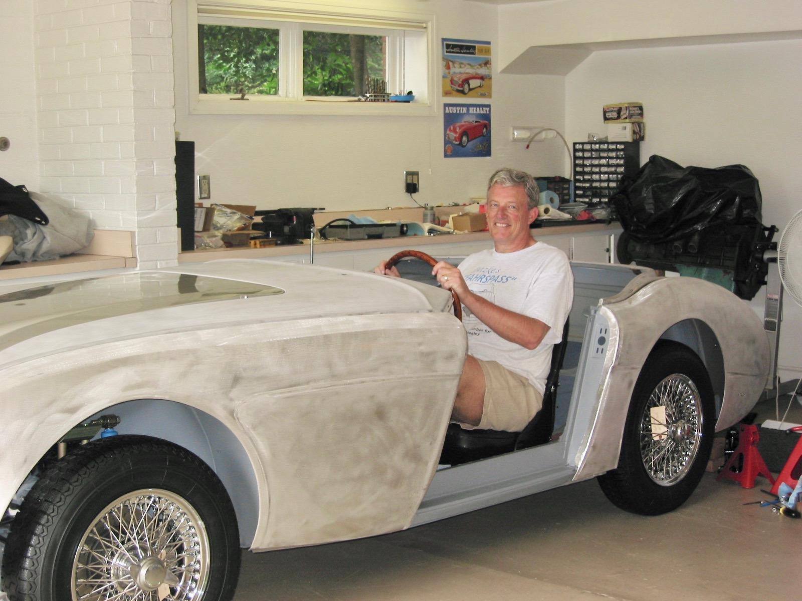
1st sitting
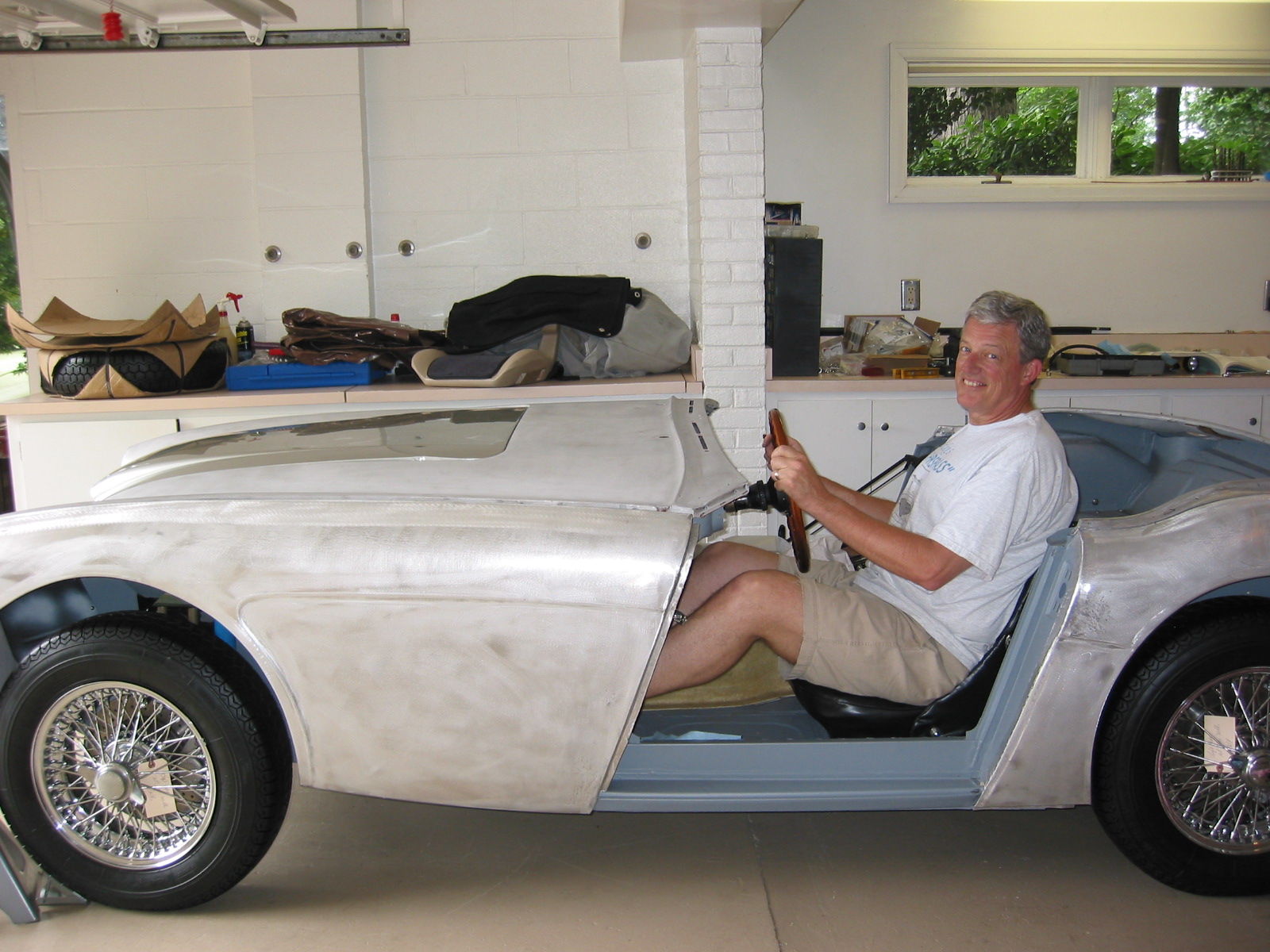
1st sitting 5
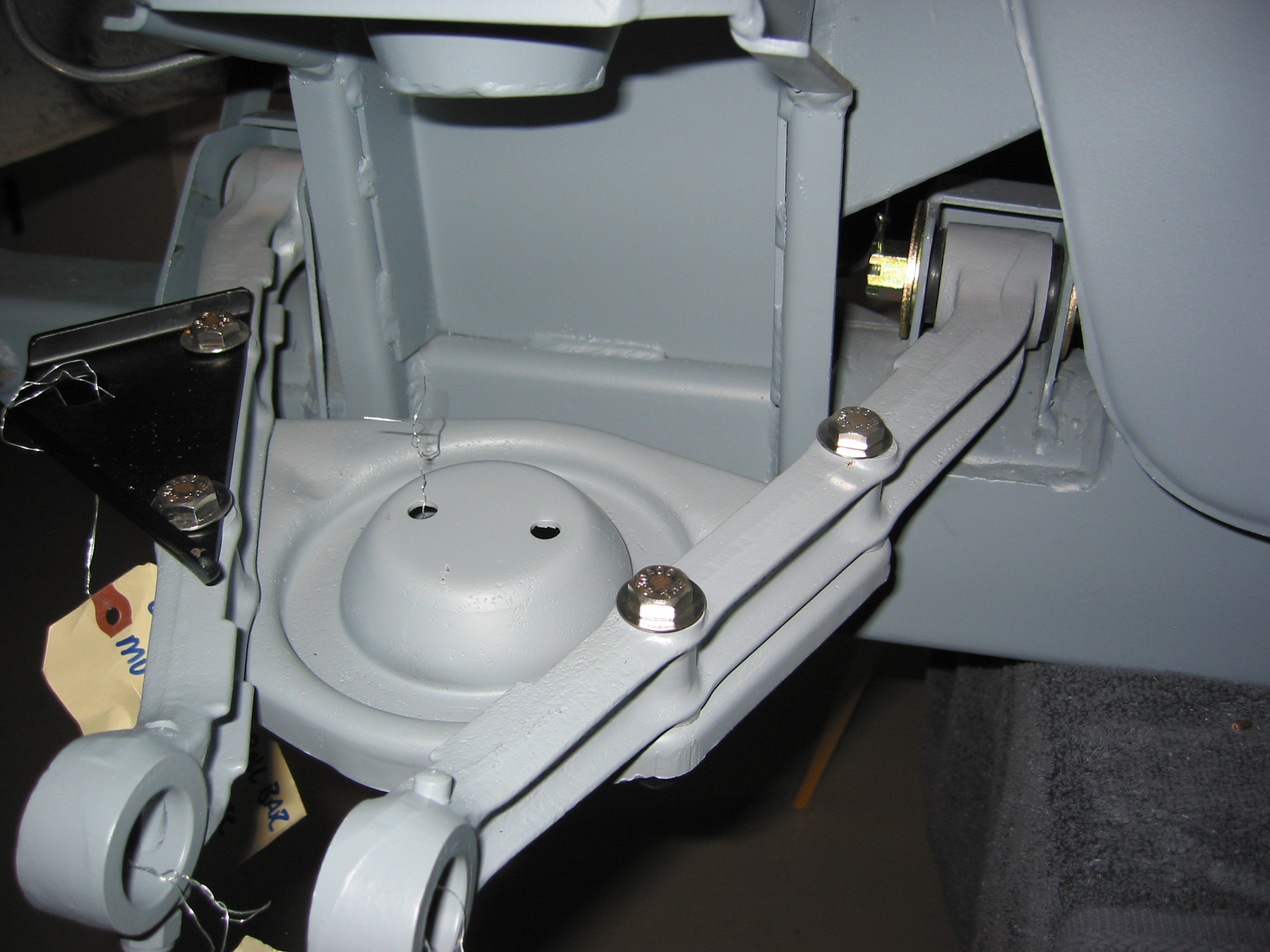
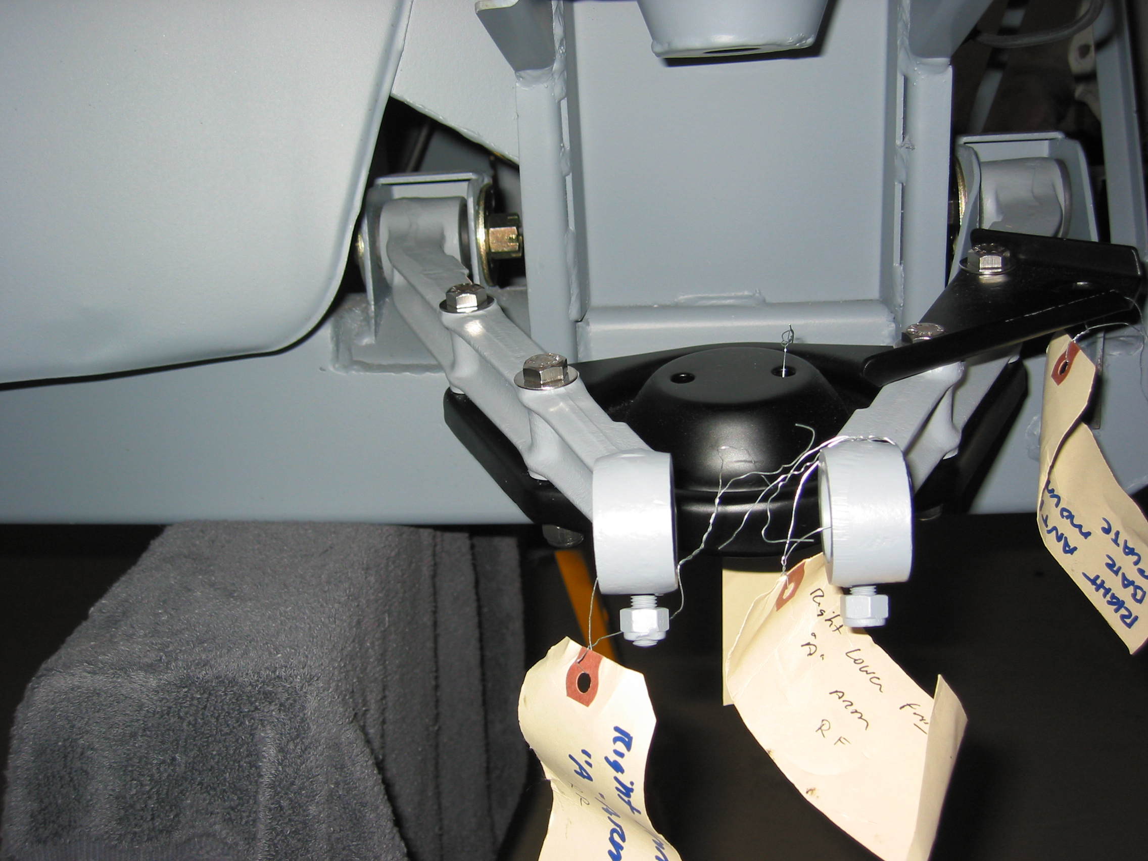
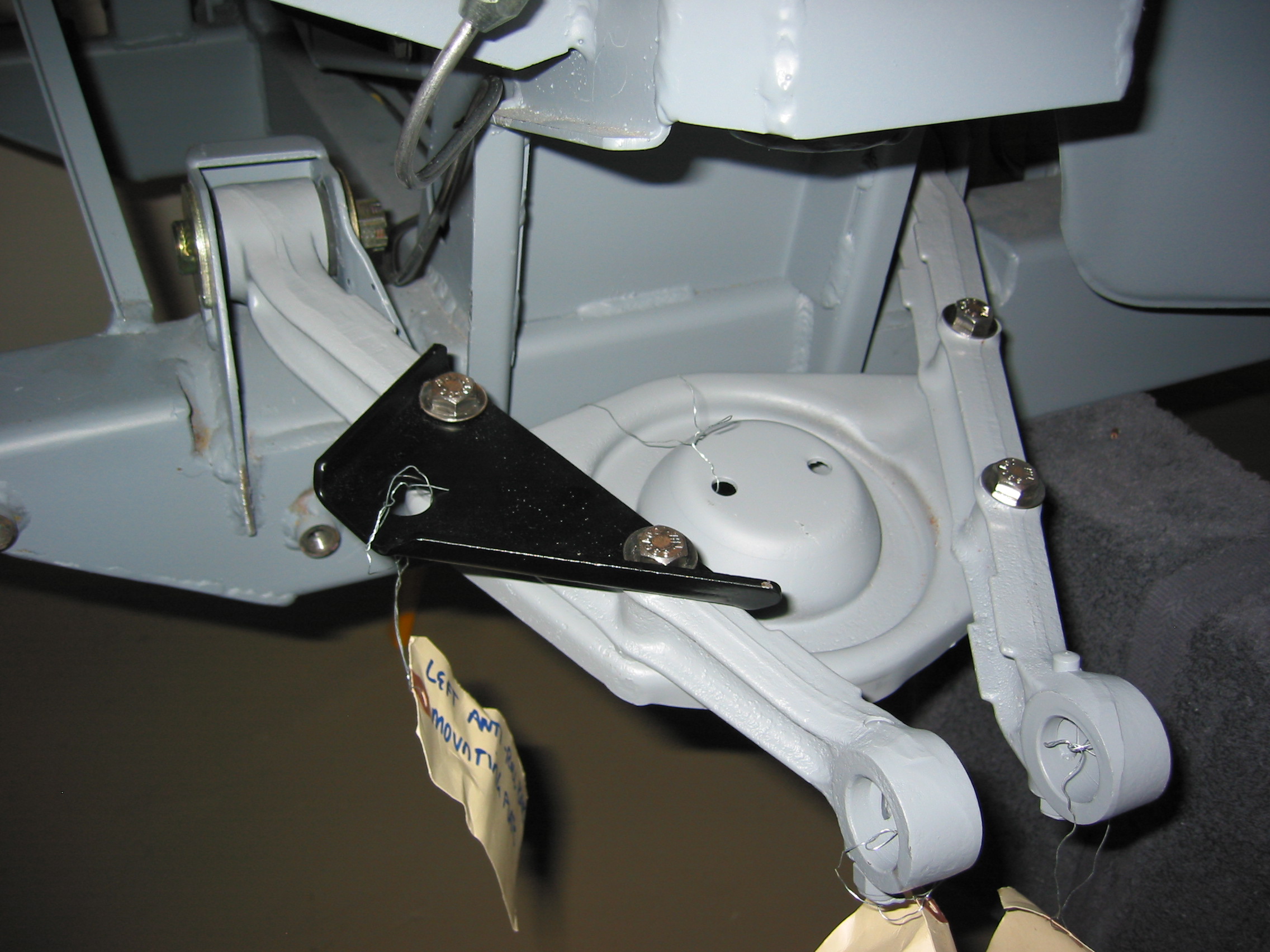
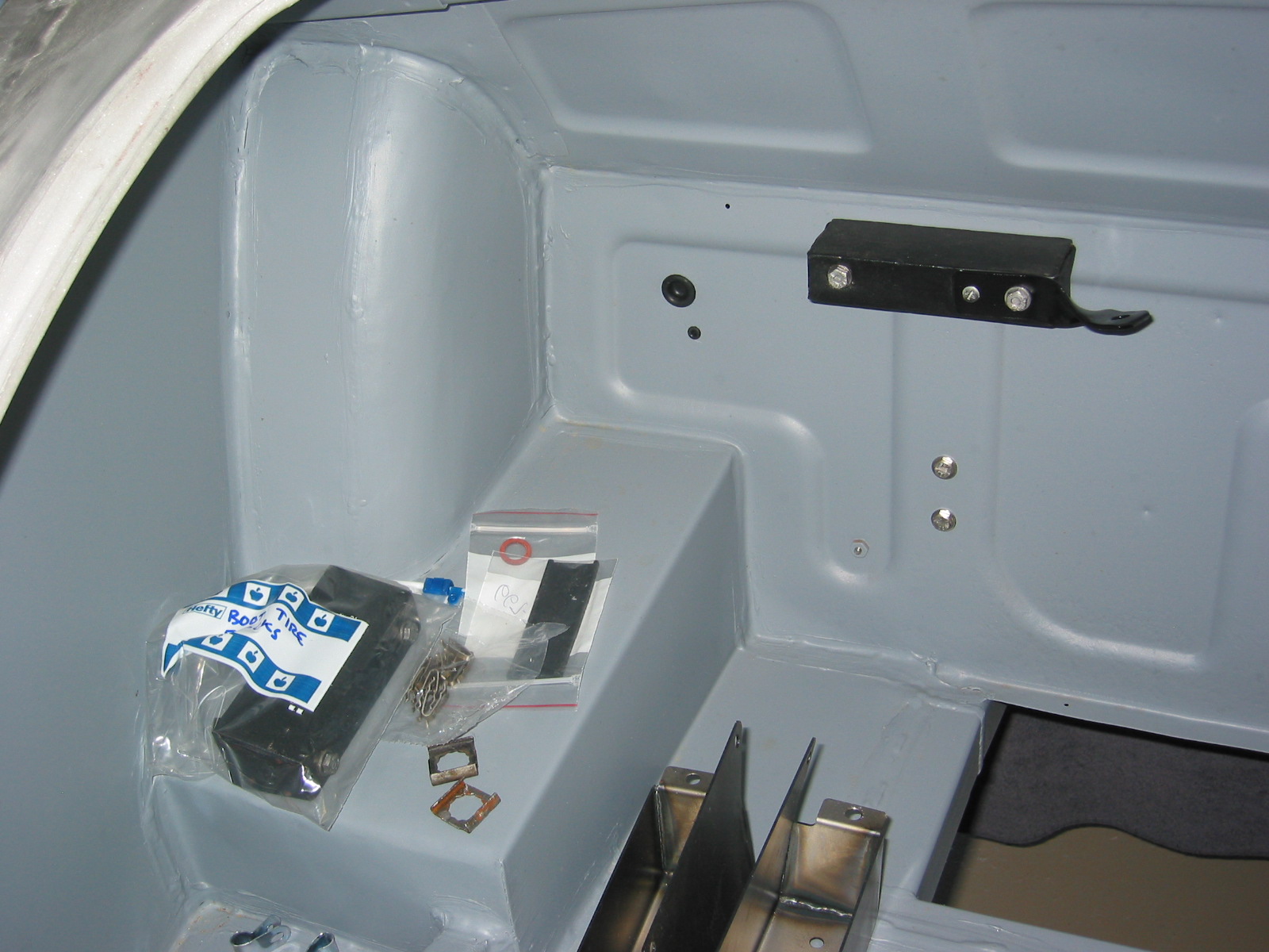
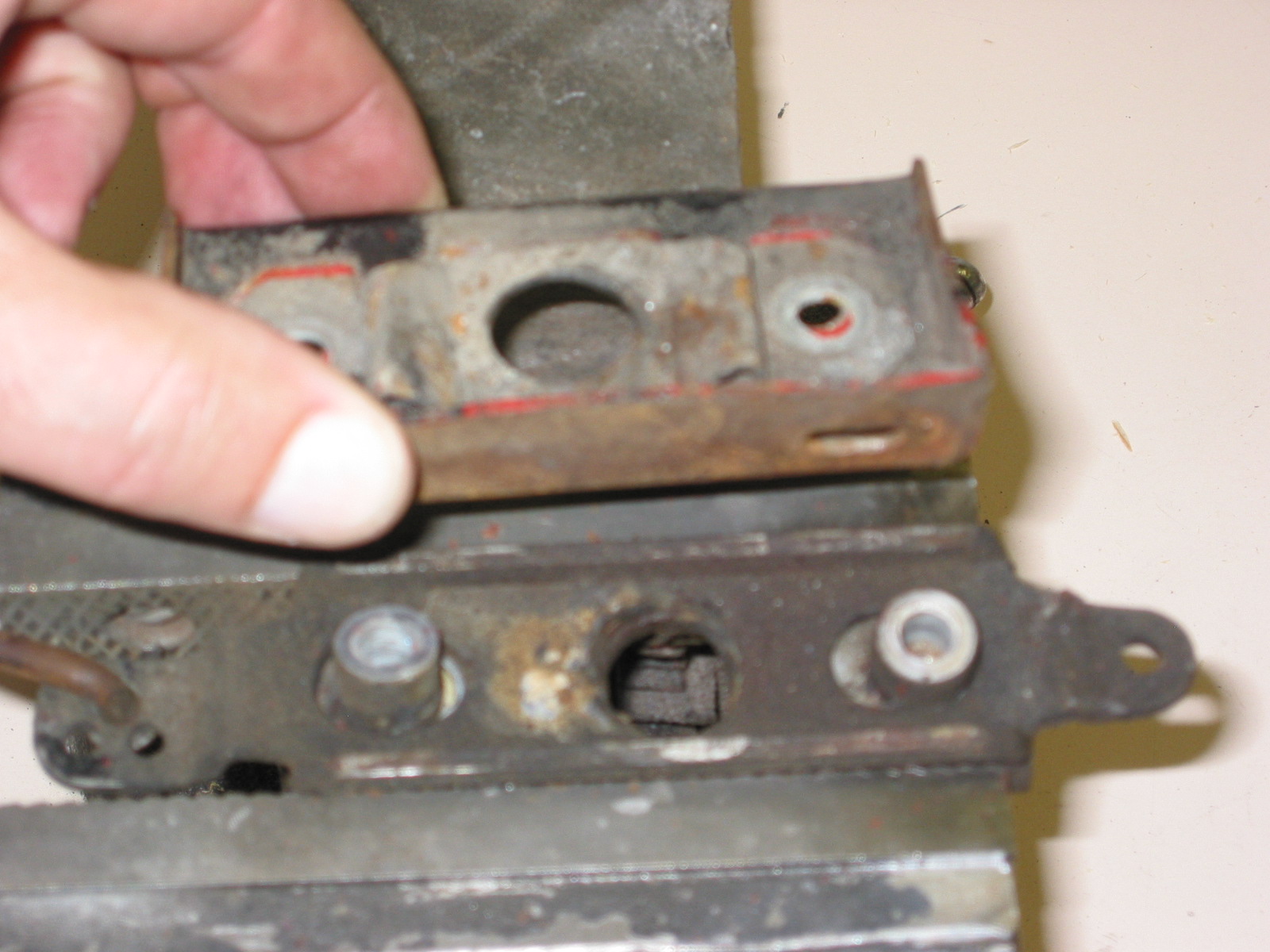
Driving Light and Tow Brackets – I received the front spotlight and tow hook brackets from Cape International and the rear bumperette (sprite) or Rally Car brackets and “bumpers.” I discovered that Martin Jansen had not included the threaded tubes for the front bumper that go through the frame. Instead Martin’s are only on the outside of the frame rails which is fine for the bumper brackets, but the spotlight tow hook brackets also have one mounting hole on the inside of the frame rails. I located the holes on the inside of the rail with 3/8” drilled hole and will get Jeremy Turner to add threaded tubes later in the restoration. I also received Kilmartin panels for the frame rails that include the welded nuts for the anti-sway bar and I will give them to Jeremy as well.
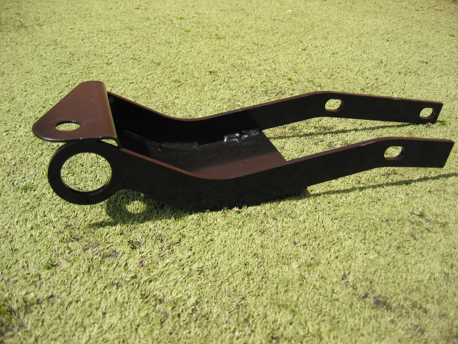
Driving light tow hook bracket
Driving Light frame Hole
anti-sway bar frame bracket
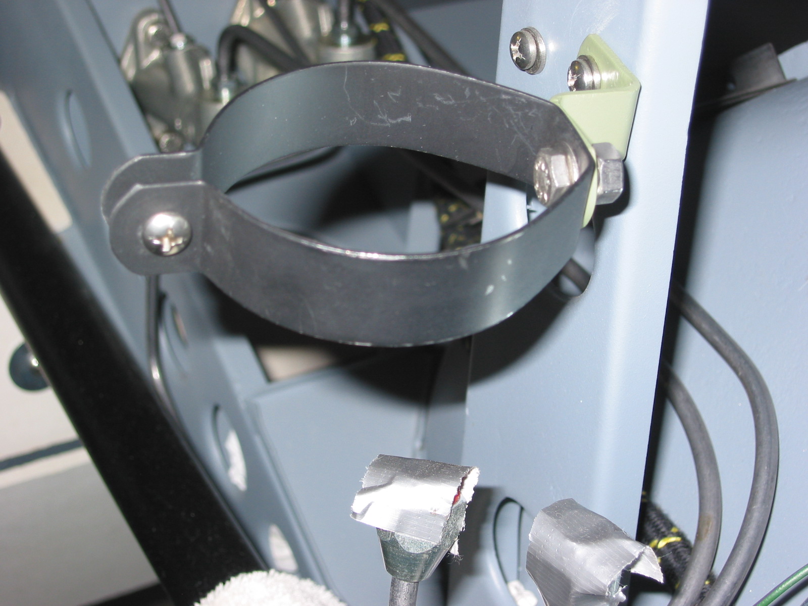
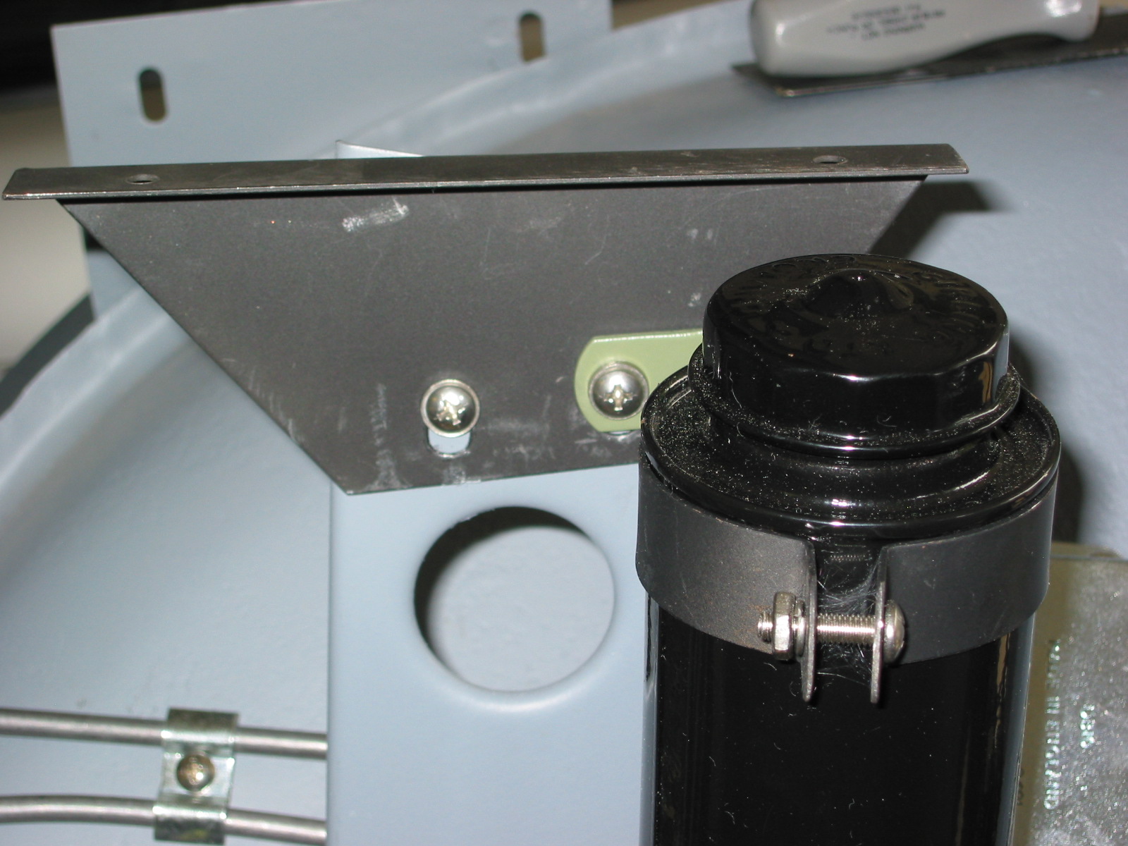
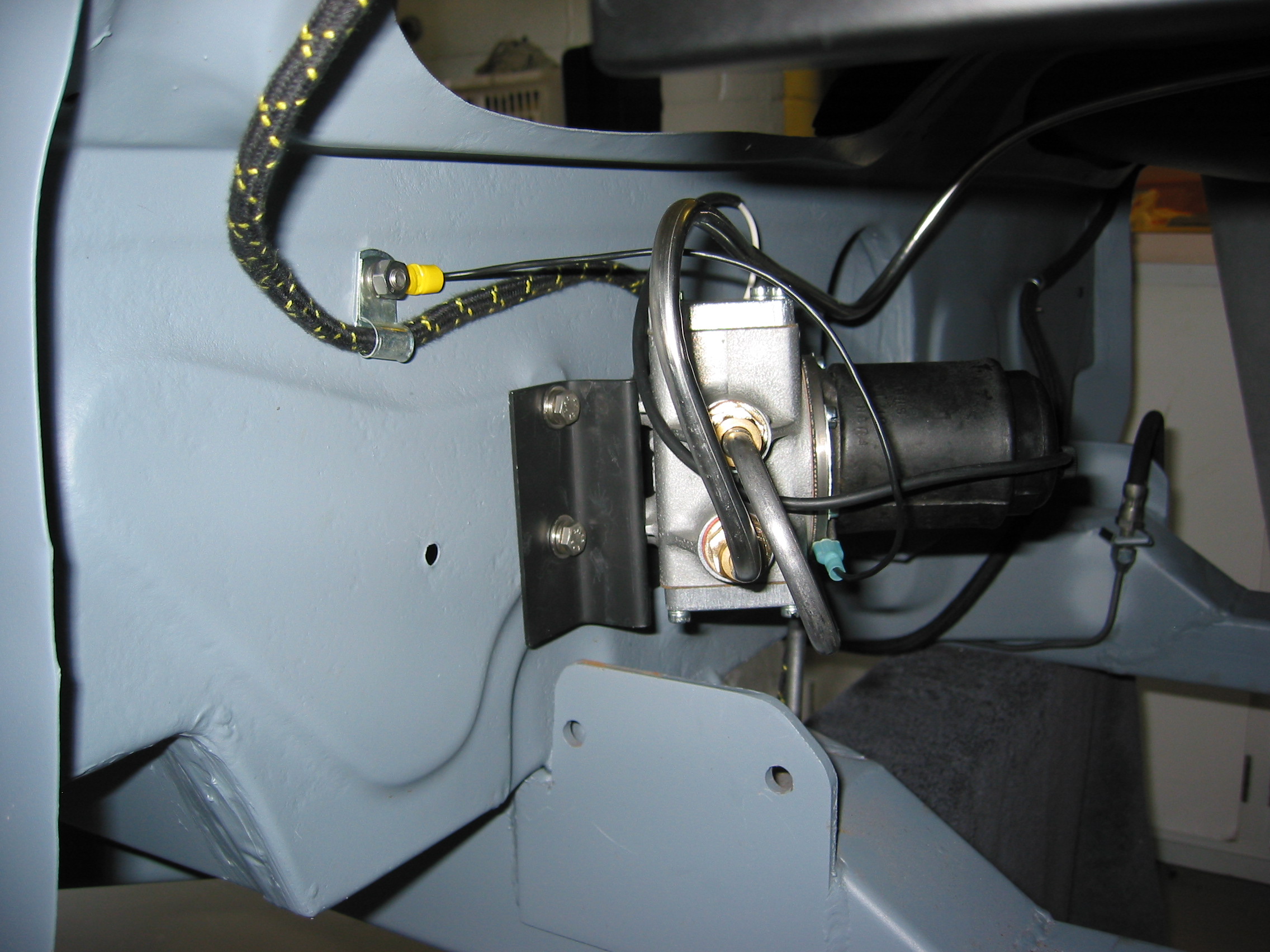
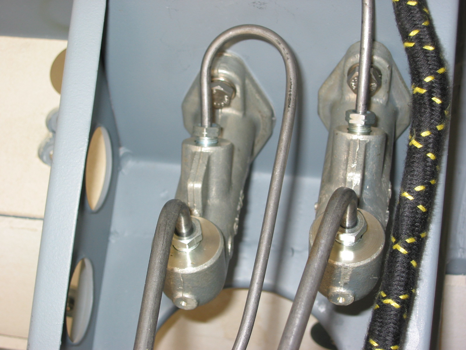
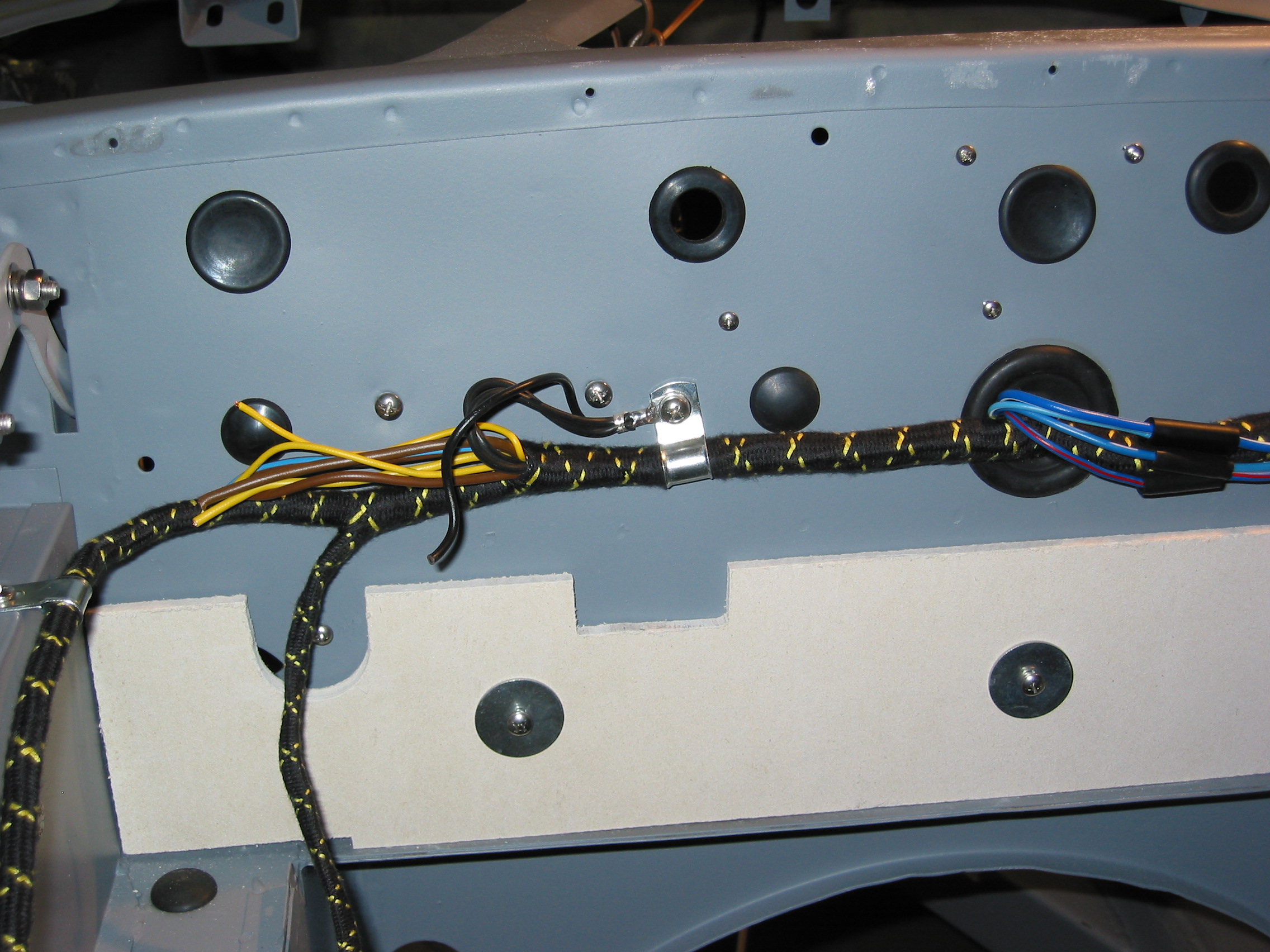
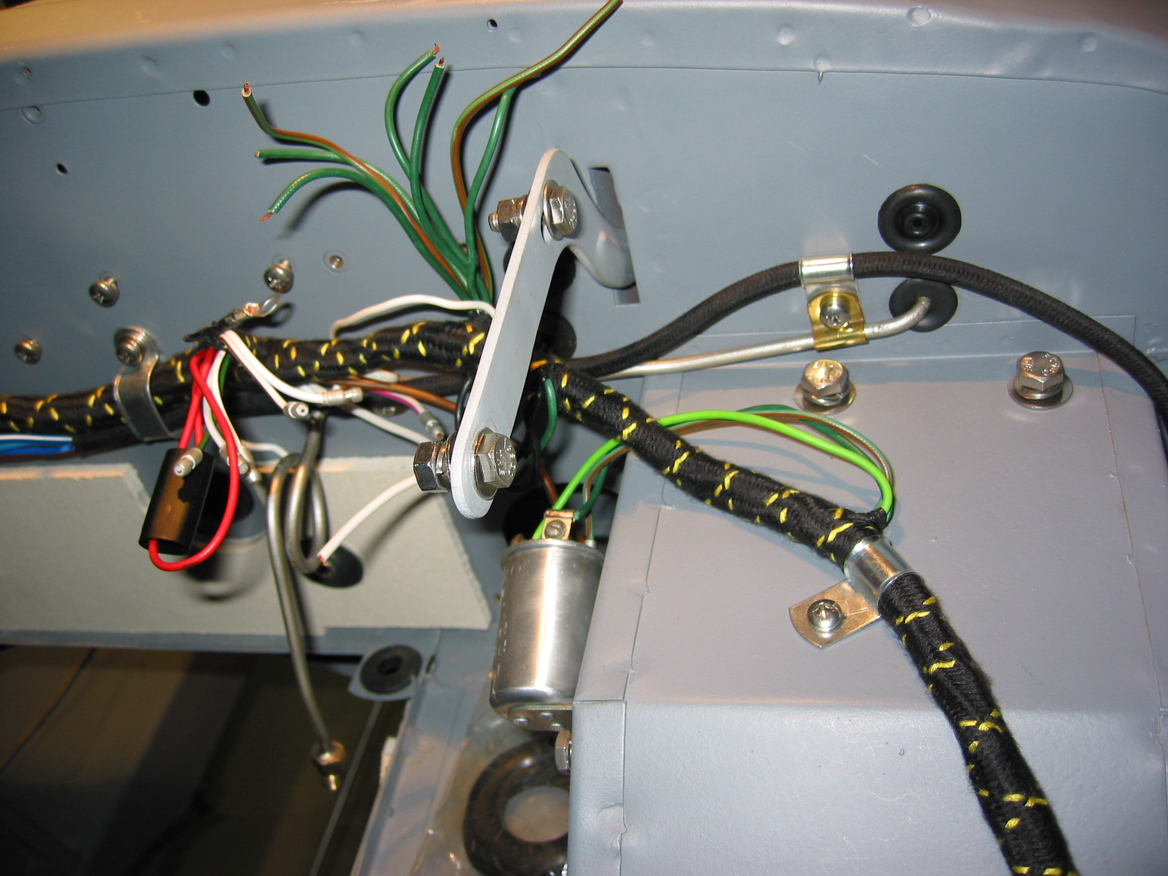
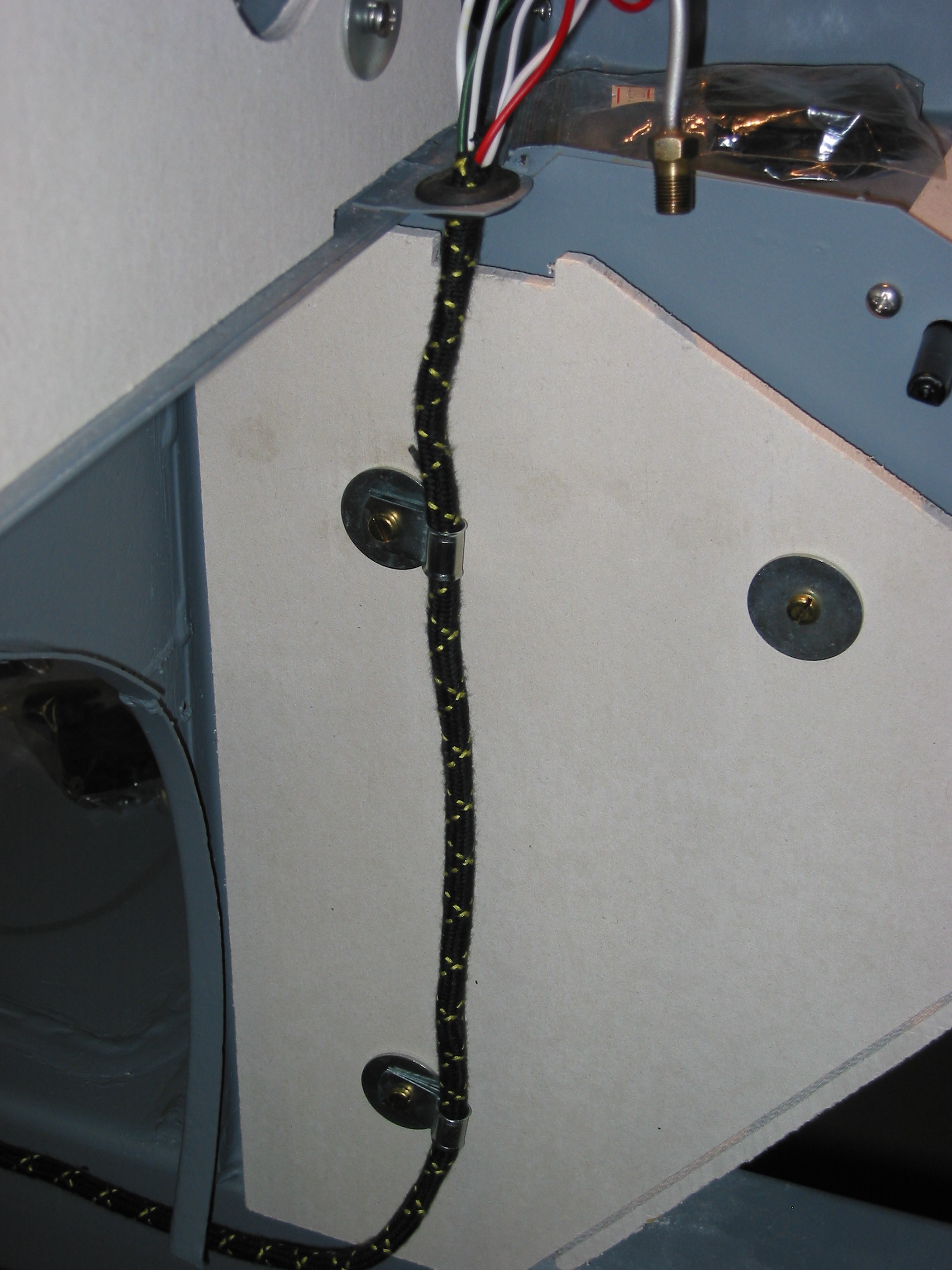
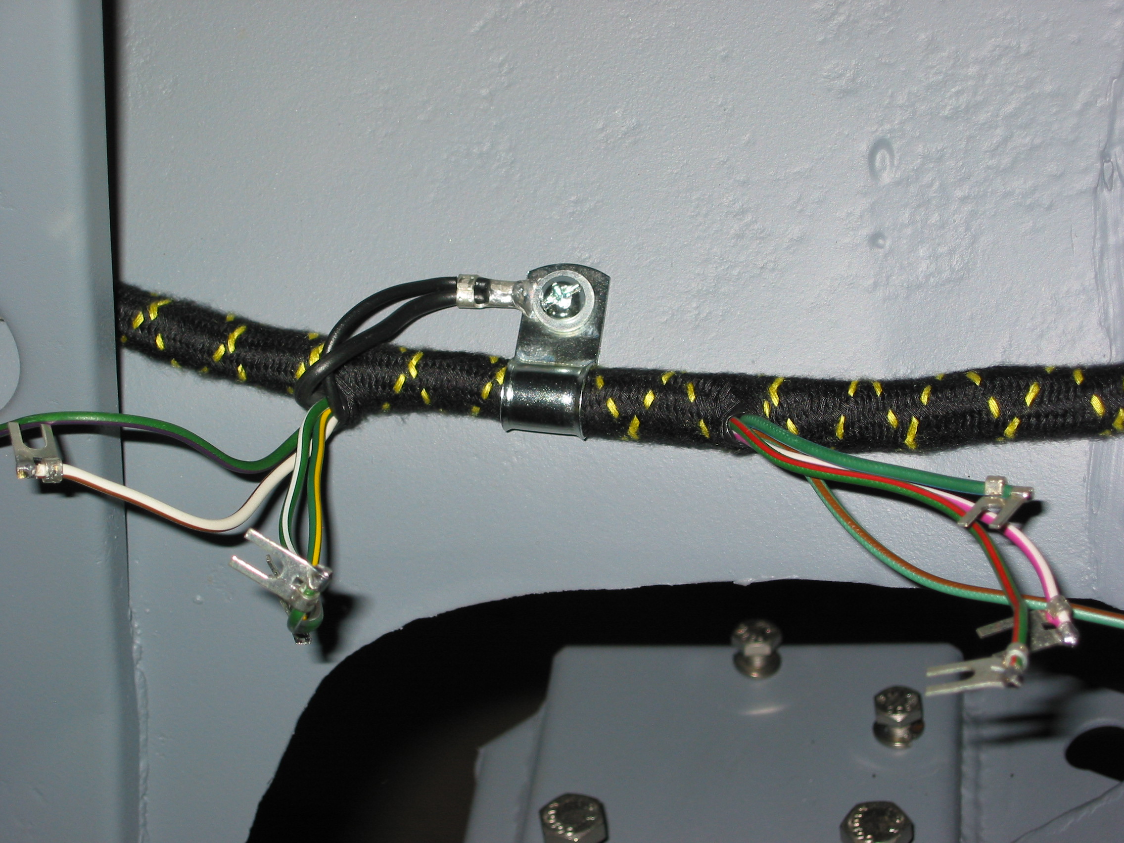
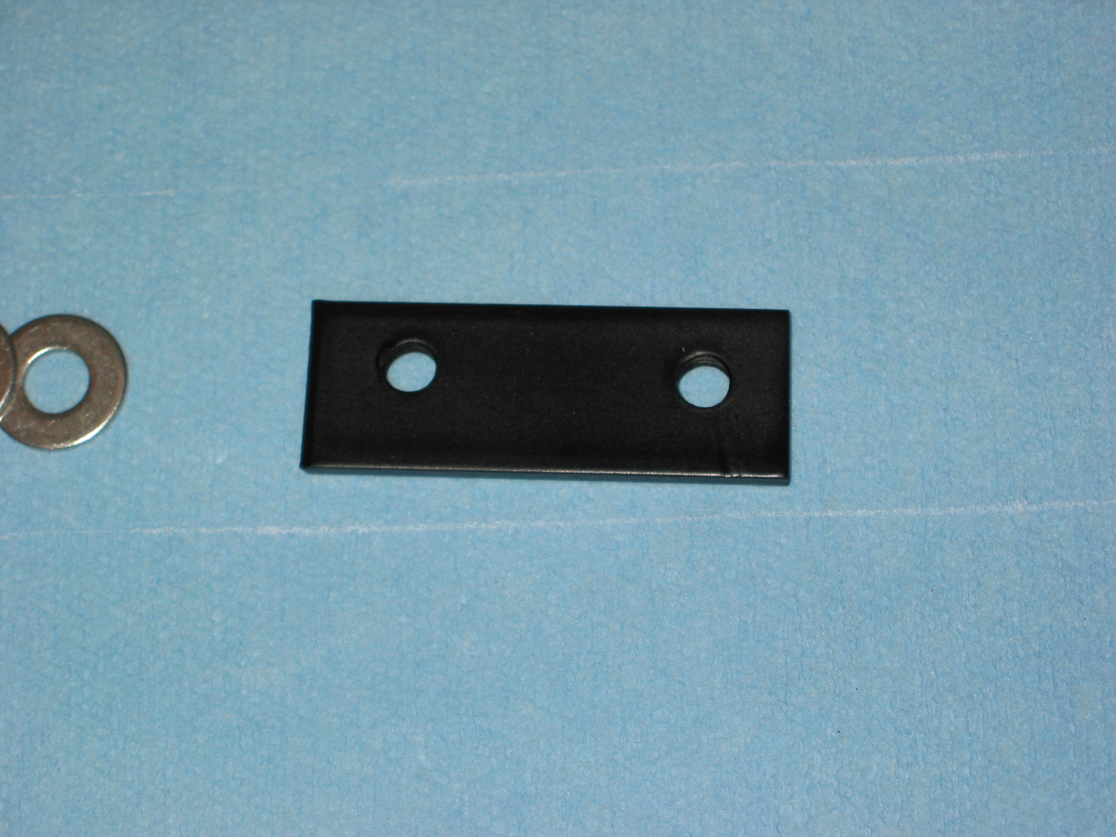
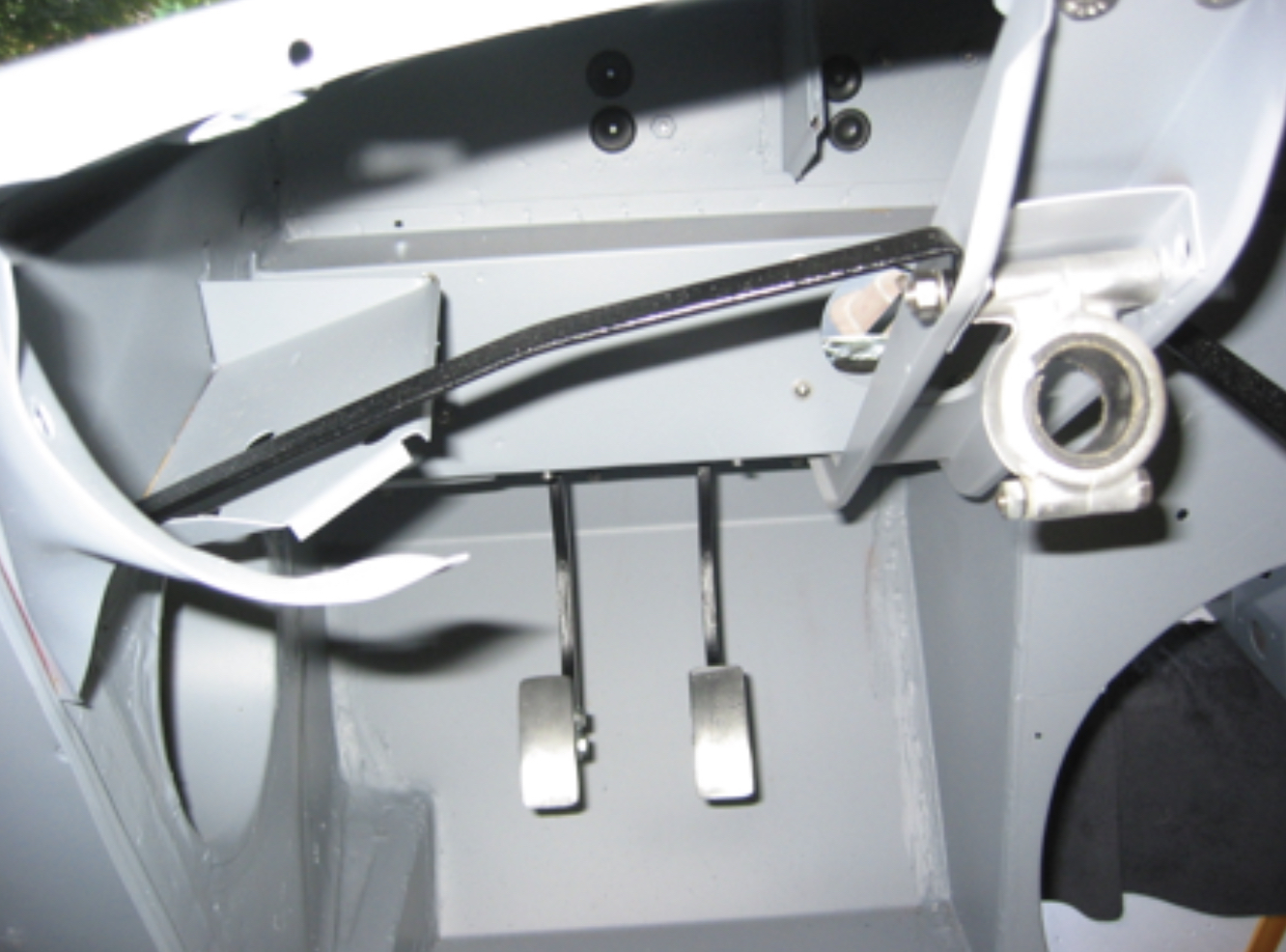
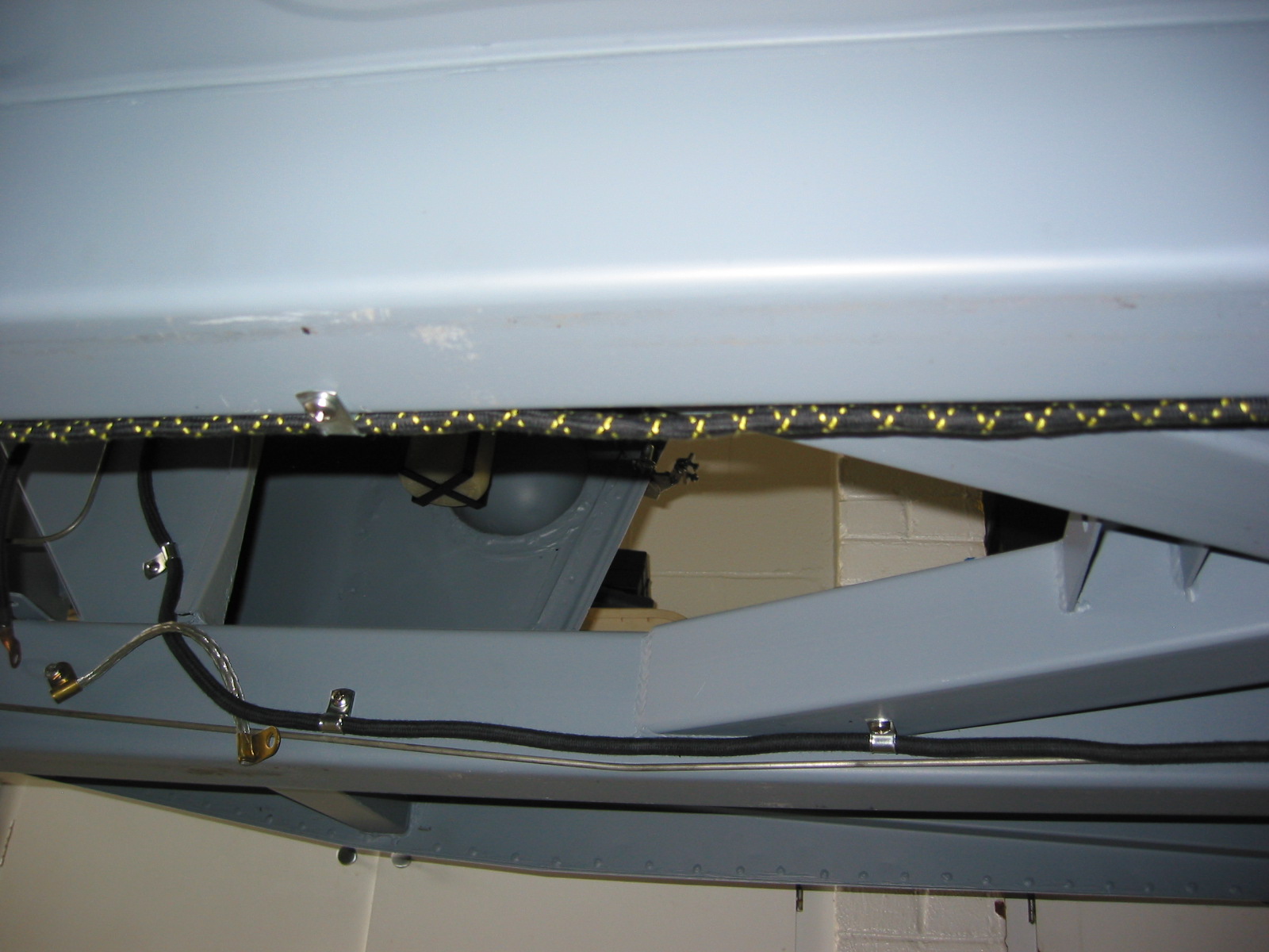
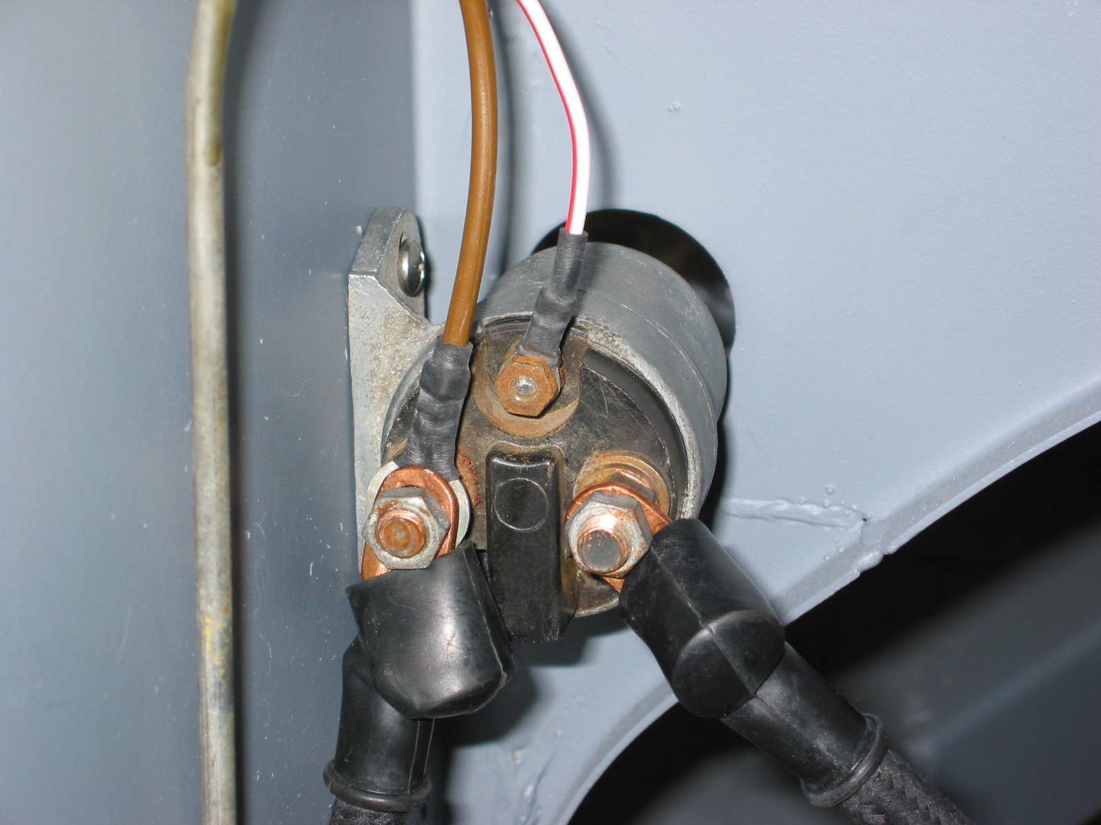
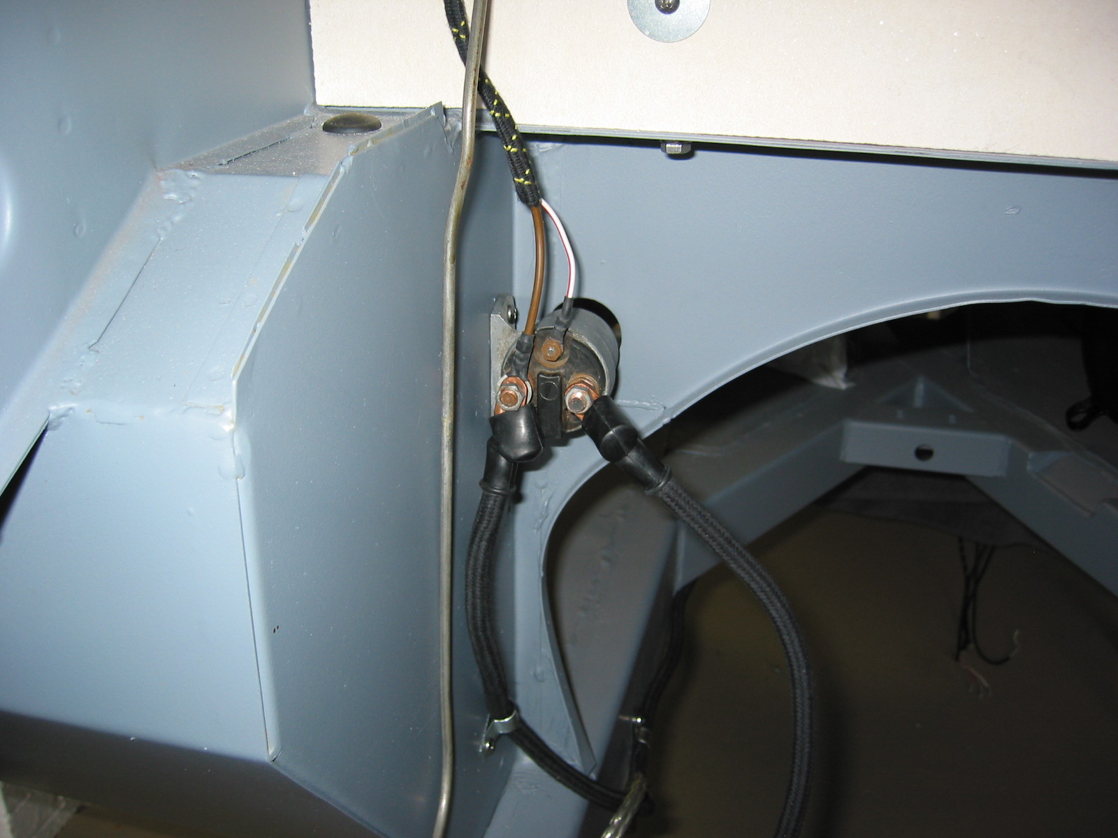
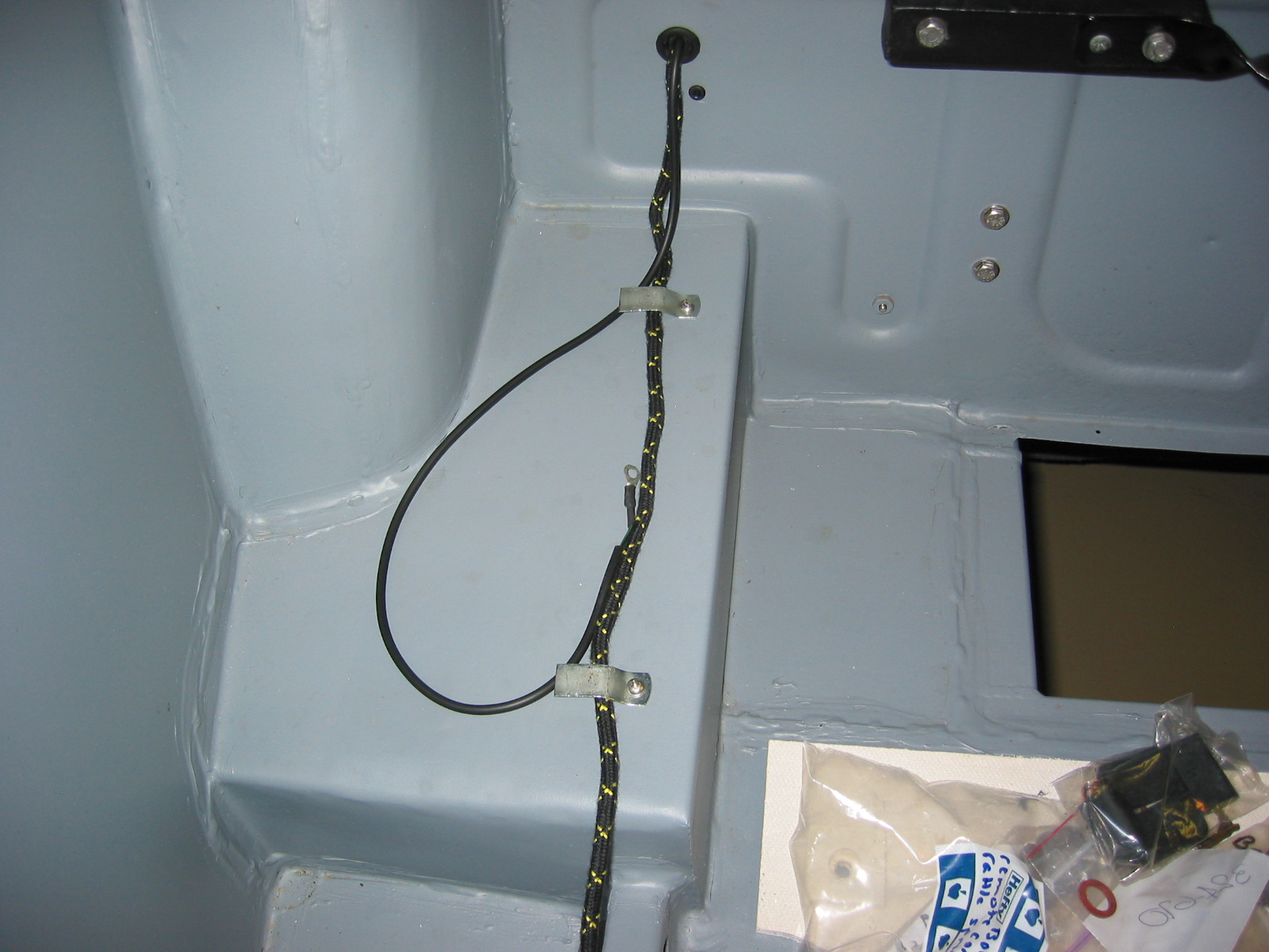
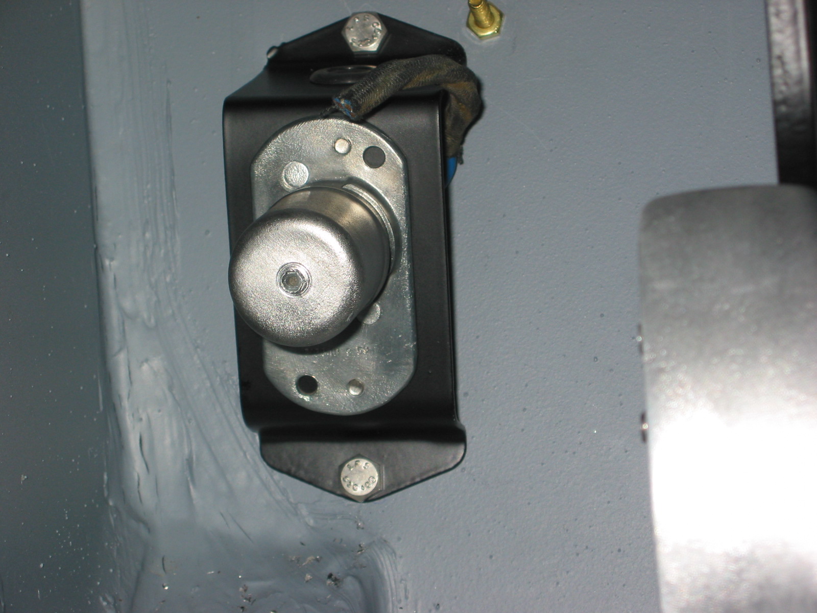
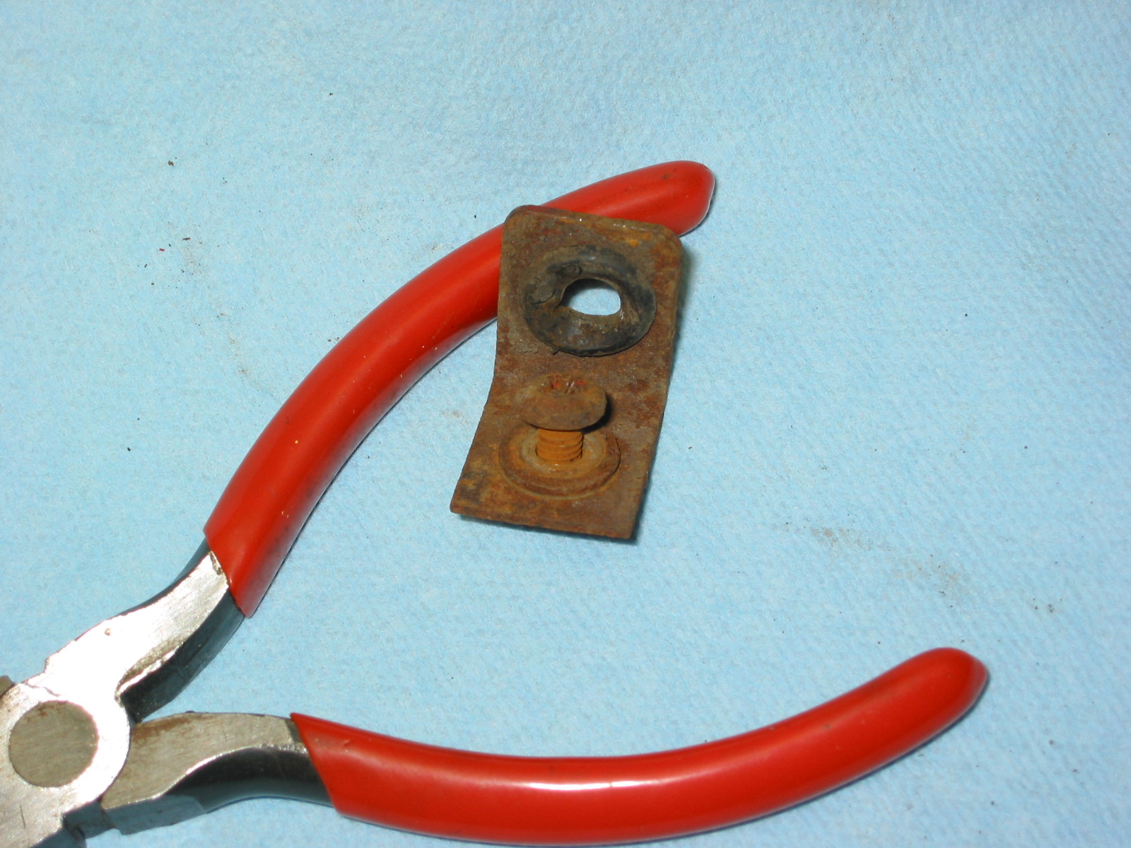
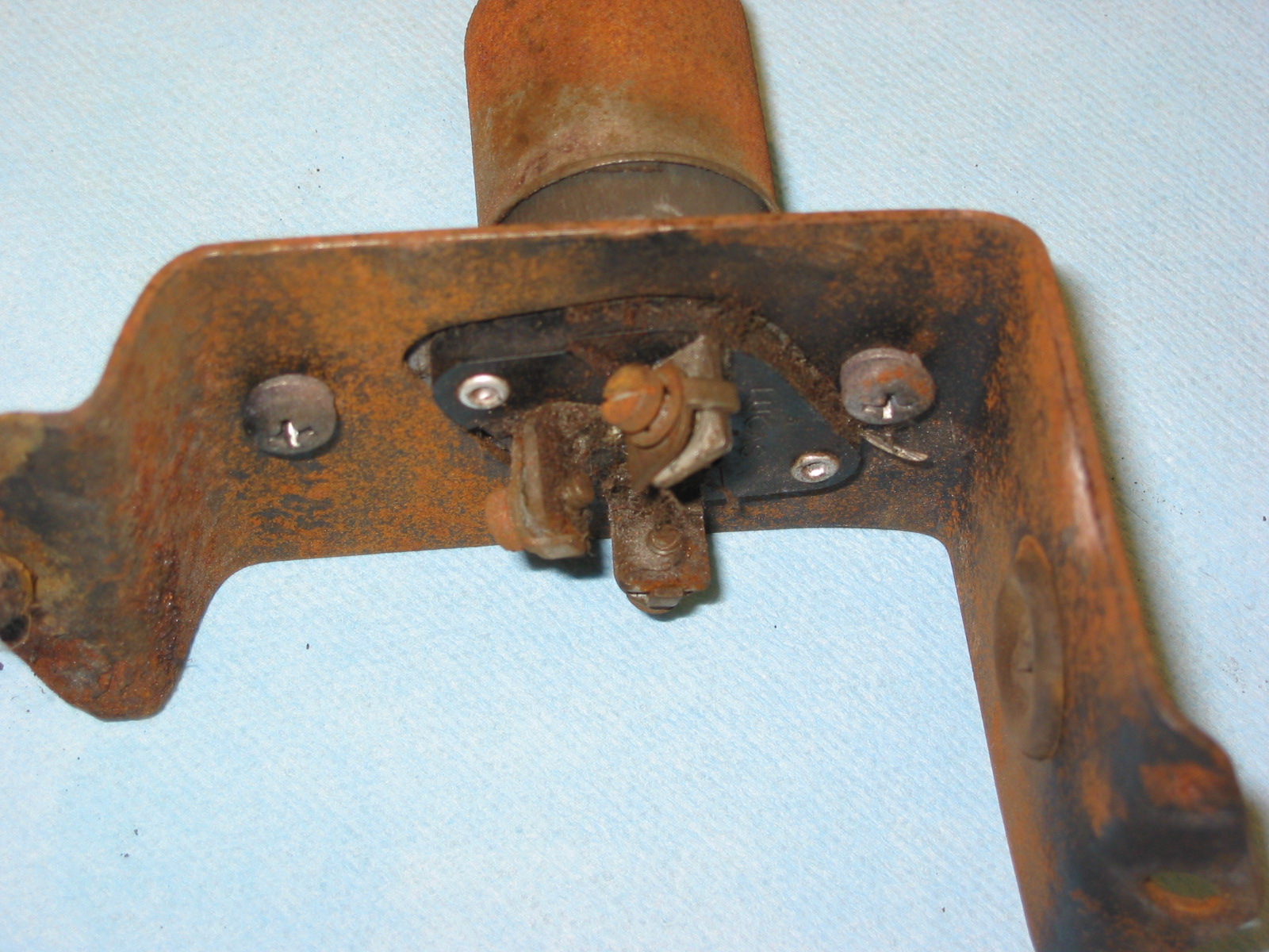
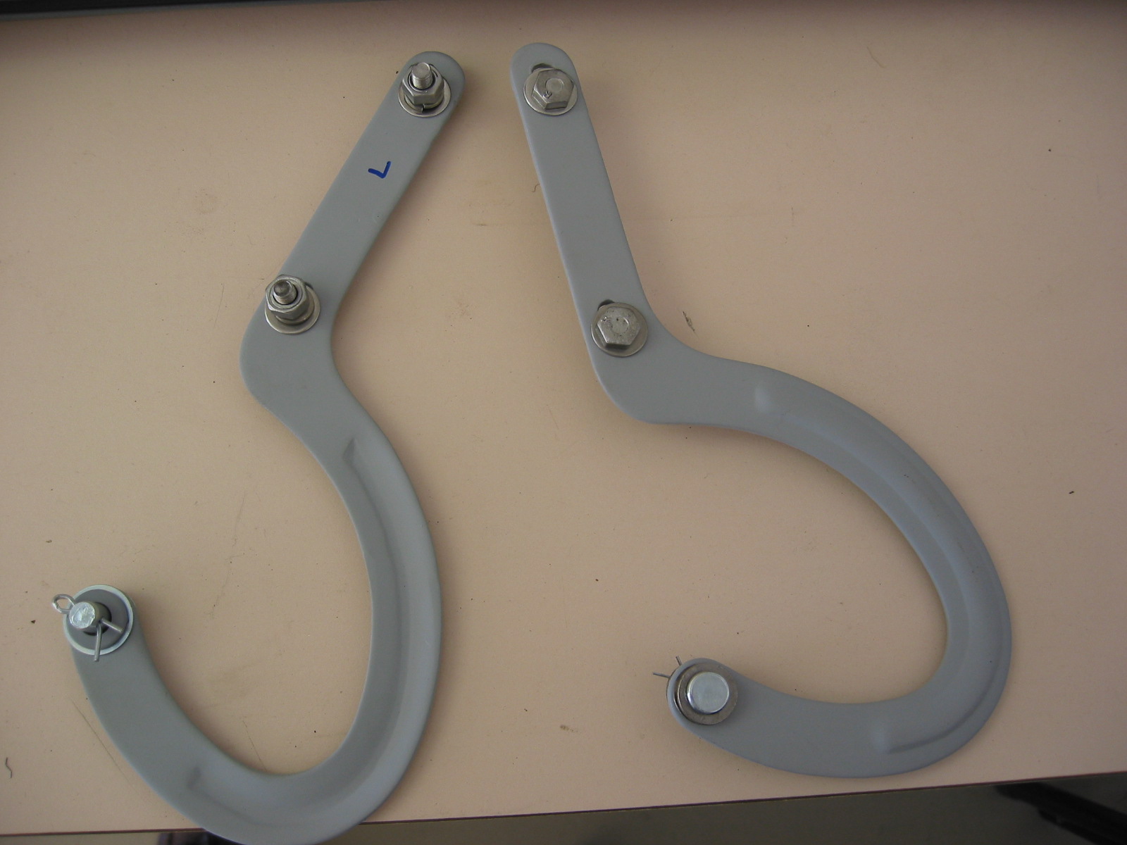
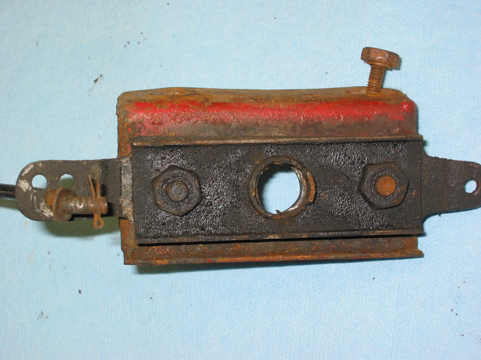
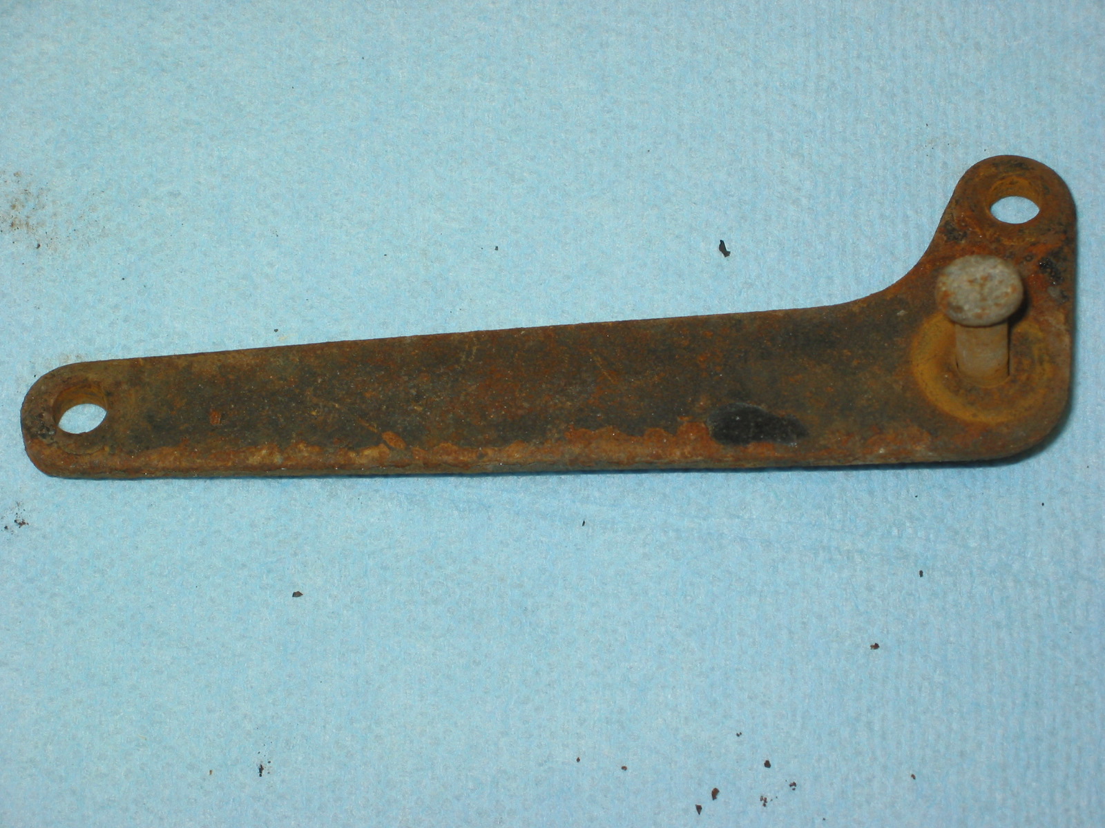
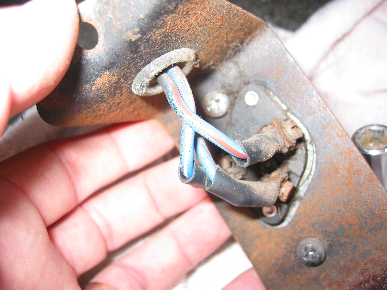
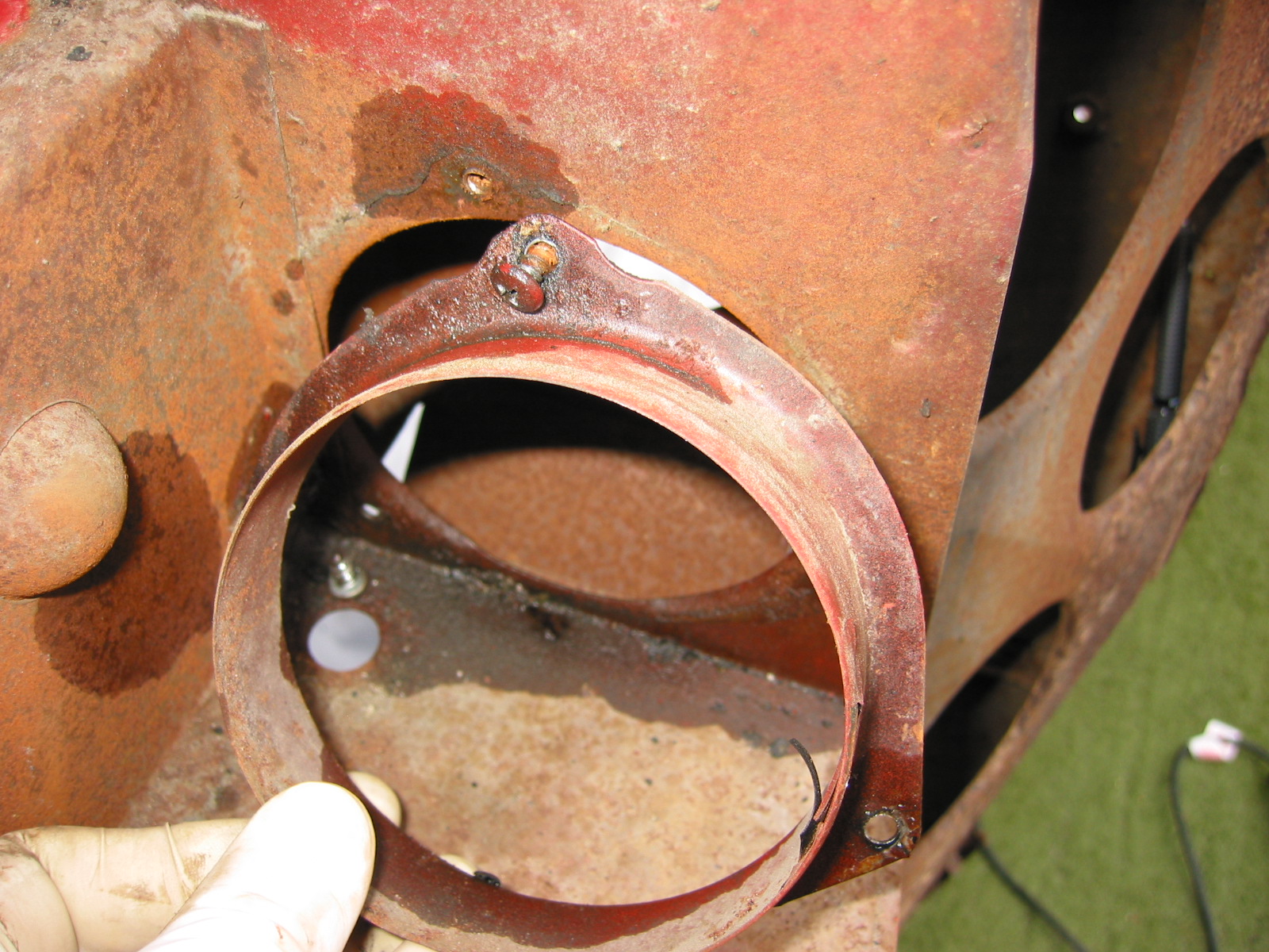
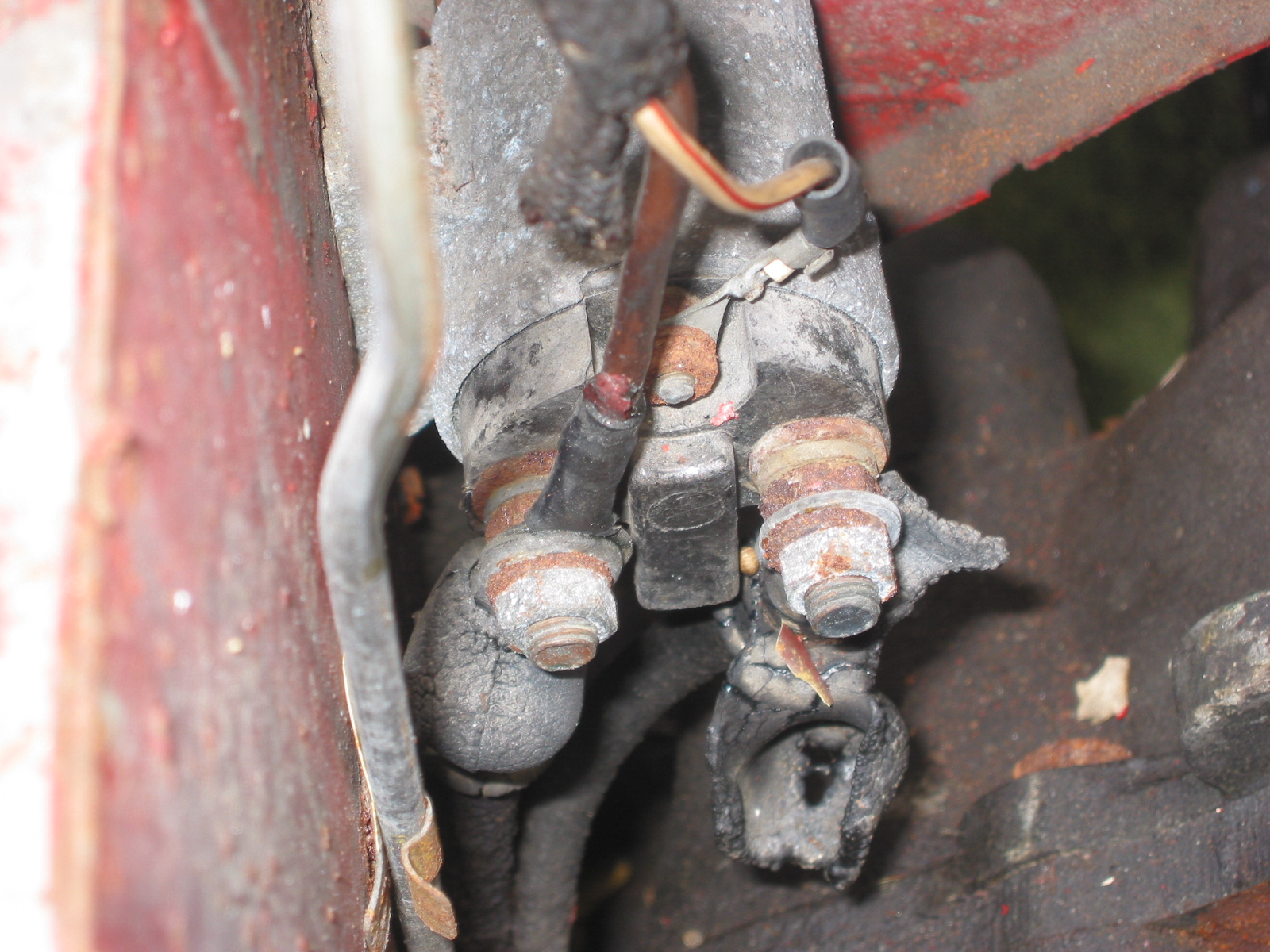
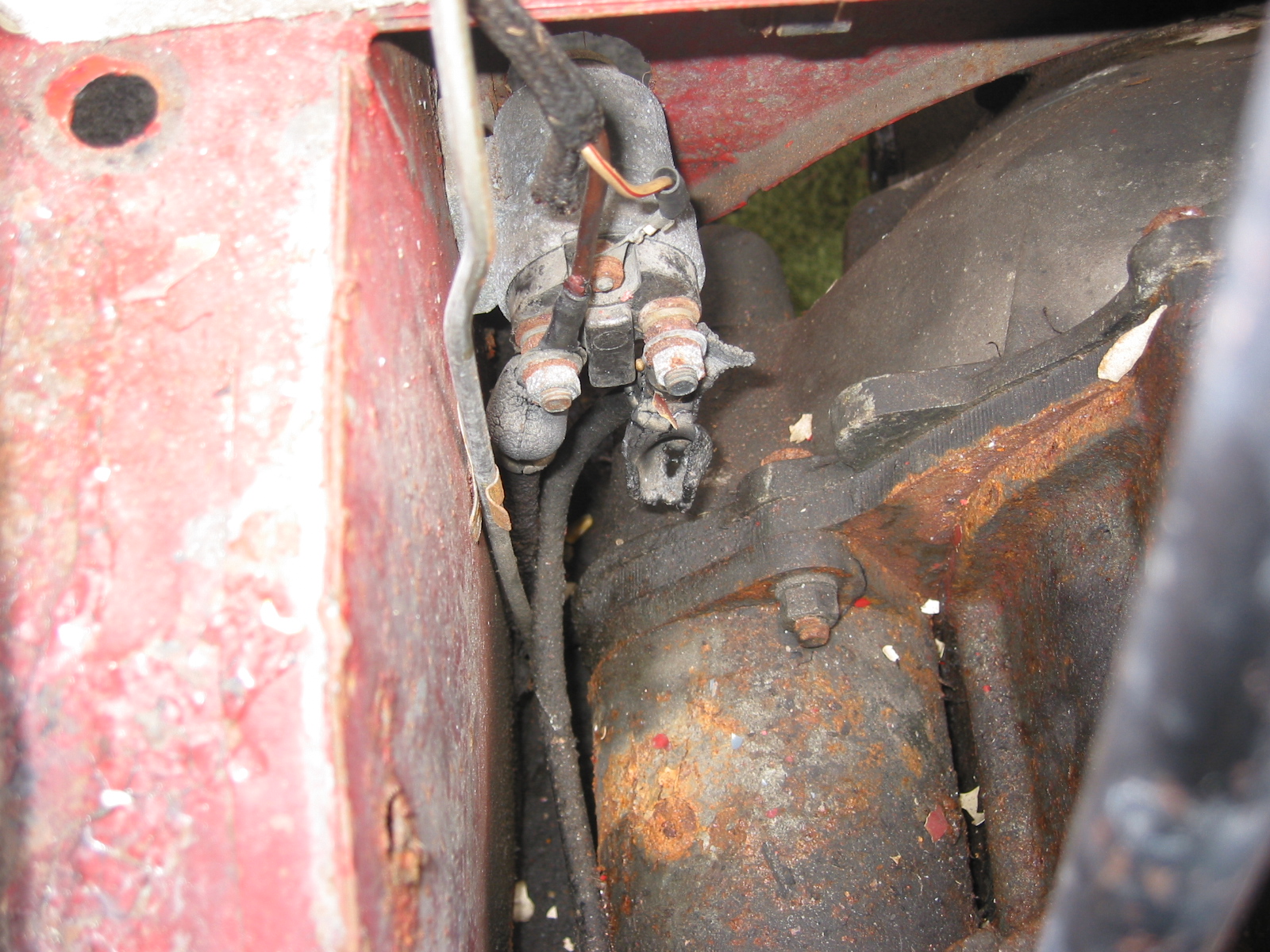
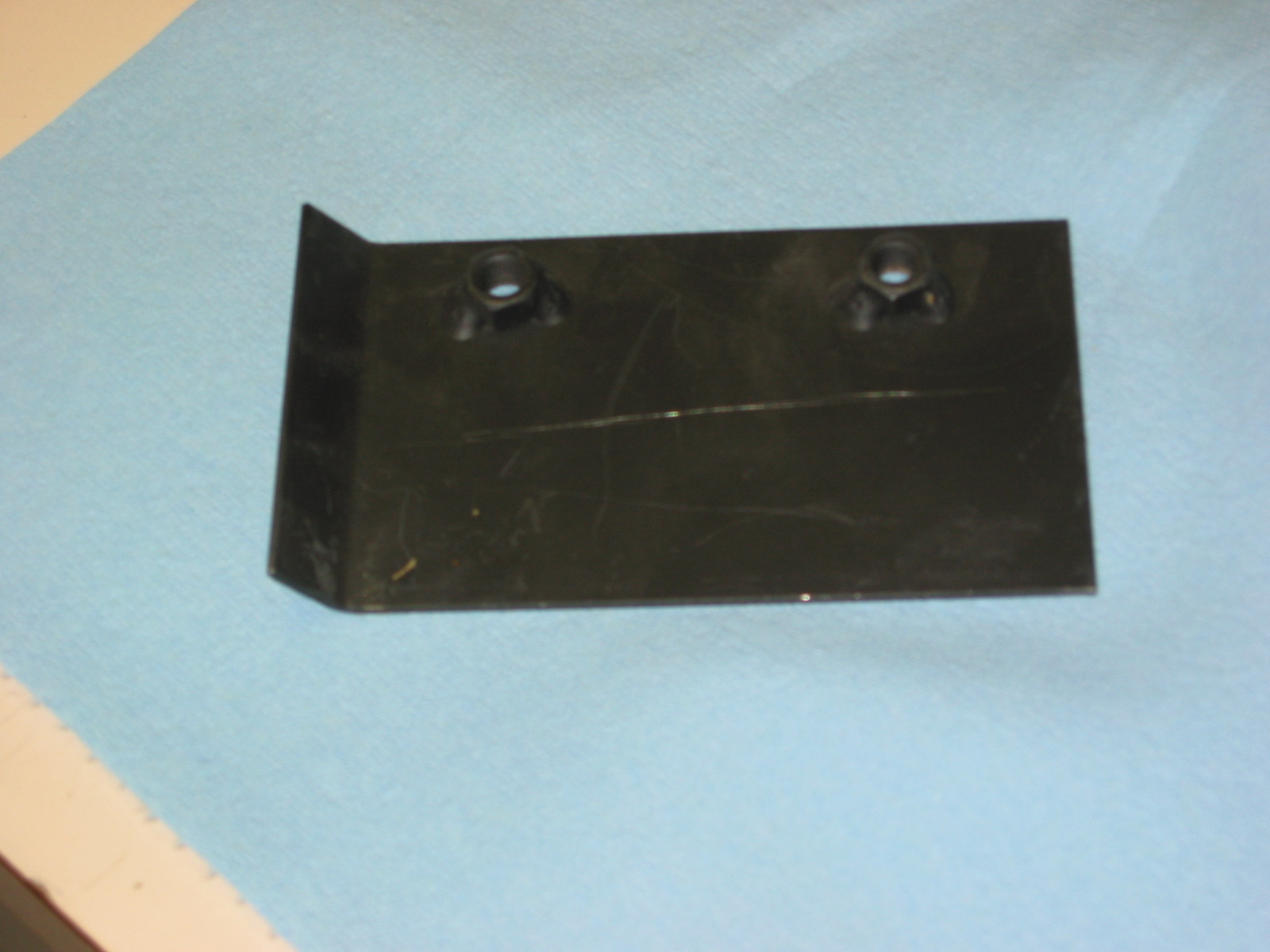
Horns – Started on the horn installation. The original horns for the Mark I are no longer available so I used the later version. The older horns must have been a little smaller in diameter, because the horns rubbed against the splash panels when connected with the brackets I had. I modified the brackets by adding a mounting hole and grinding off a bit of the bracket to “shift” the horns toward the center of the car. All of this seemed to work flawlessly, but once again I encountered a job that probably should have taken 10 minutes that ended up taking two hours. The horn wiring harness extensions provided by British Wiring were not needed so I crimped some new connectors on the wire in place of the original bullet connectors and attached them to the horns. The new horns were interesting – both brand new – one gloss black and one satin. I will have Jeremy repaint them.
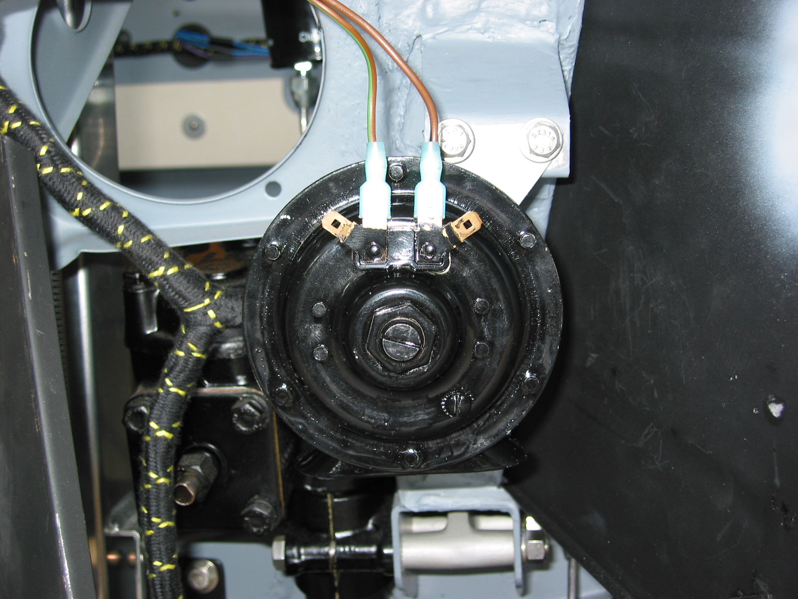
Horn install left
June 18, 2004
Fuel Sender Unit – Installed the fuel sender unit in the new aluminum fuel tank. The sender unit did not line up exactly as the original because the holes in the tank are not as they were in the steel tank. I sealed the sender unit with a new cork gasket and with Hylomar. Each of the small mounting screws received new copper washers.
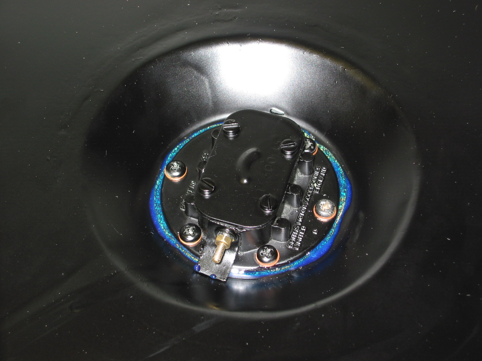
Fuel sender unit
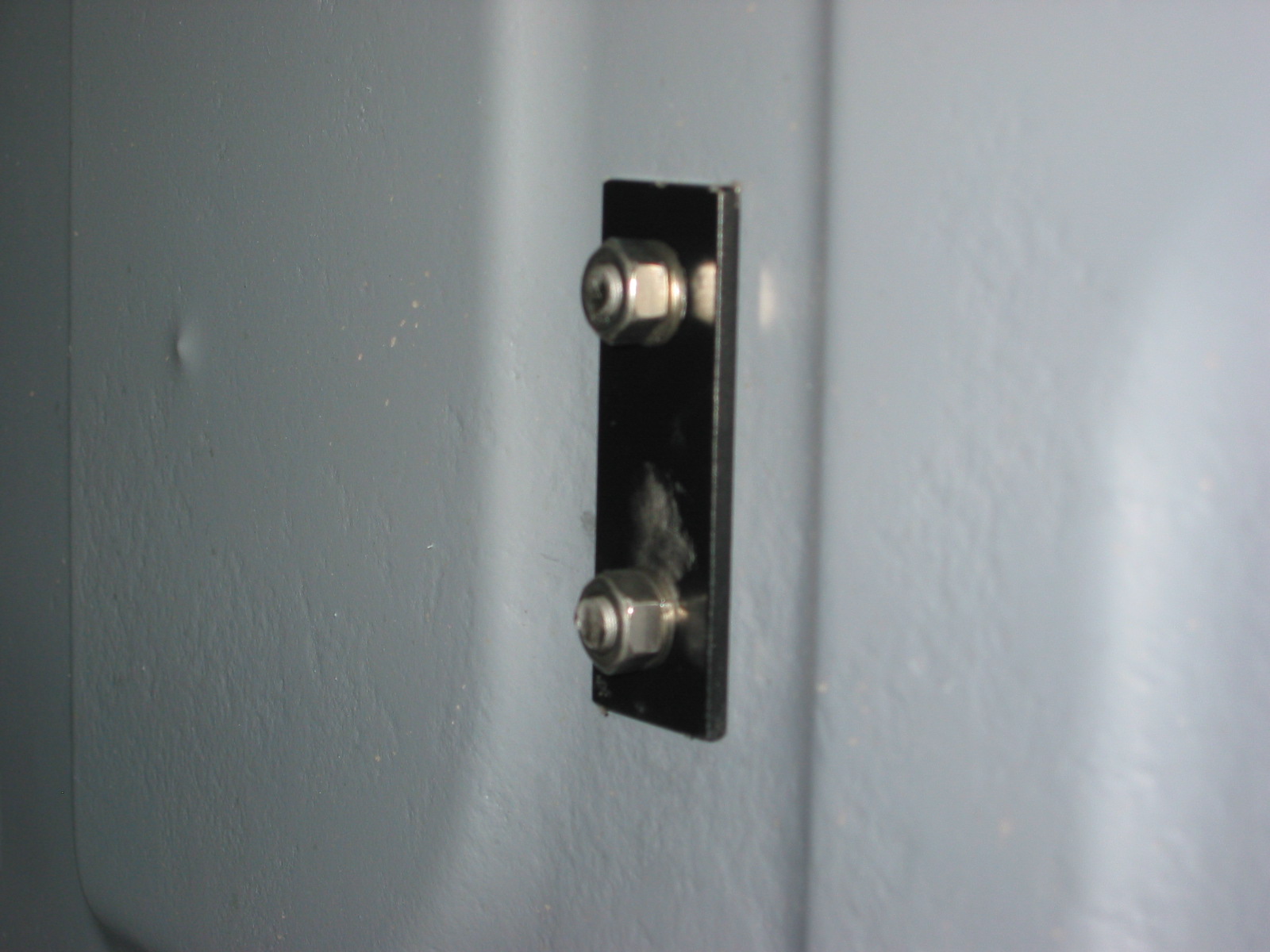
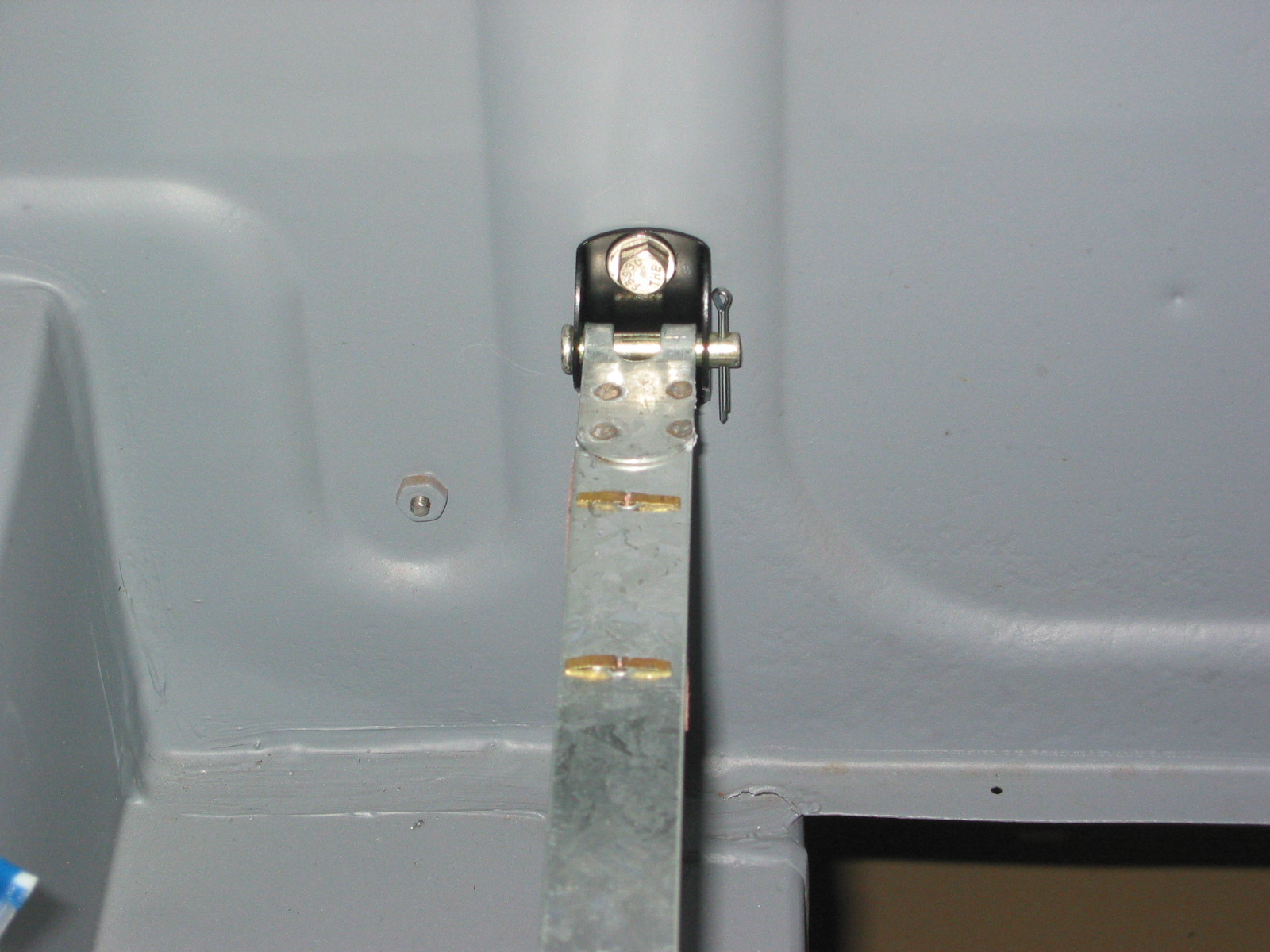
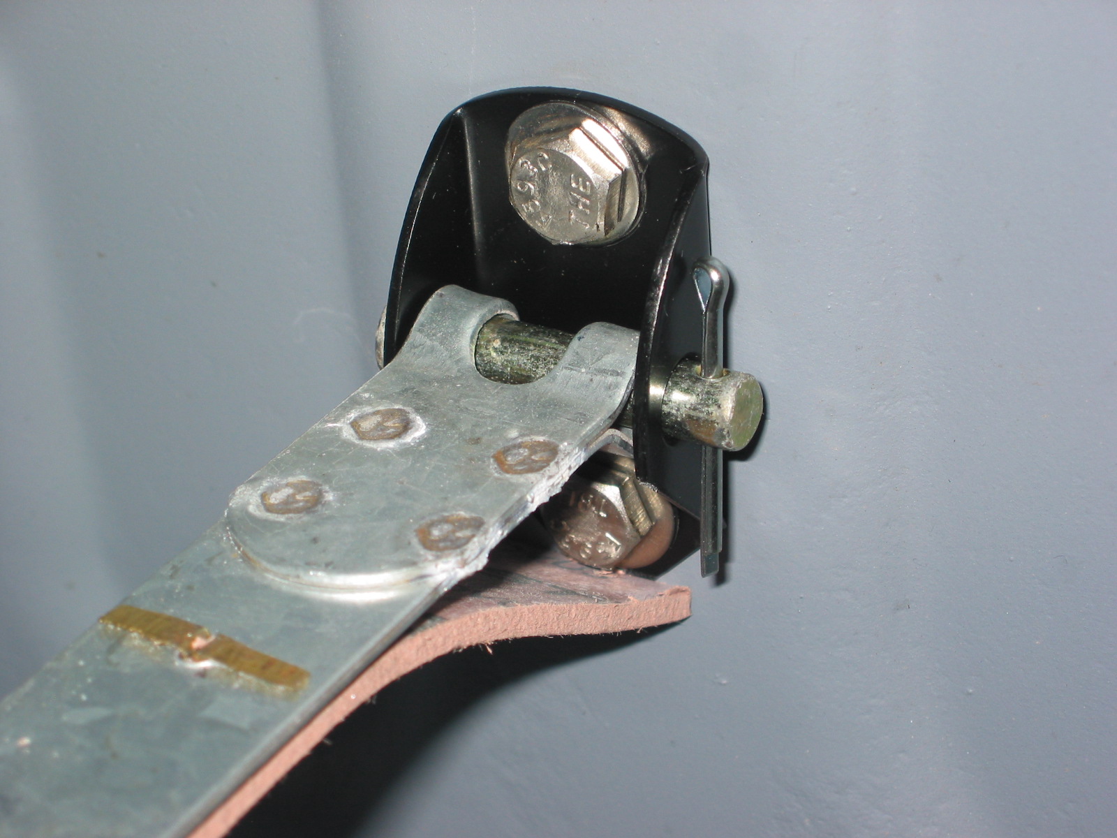
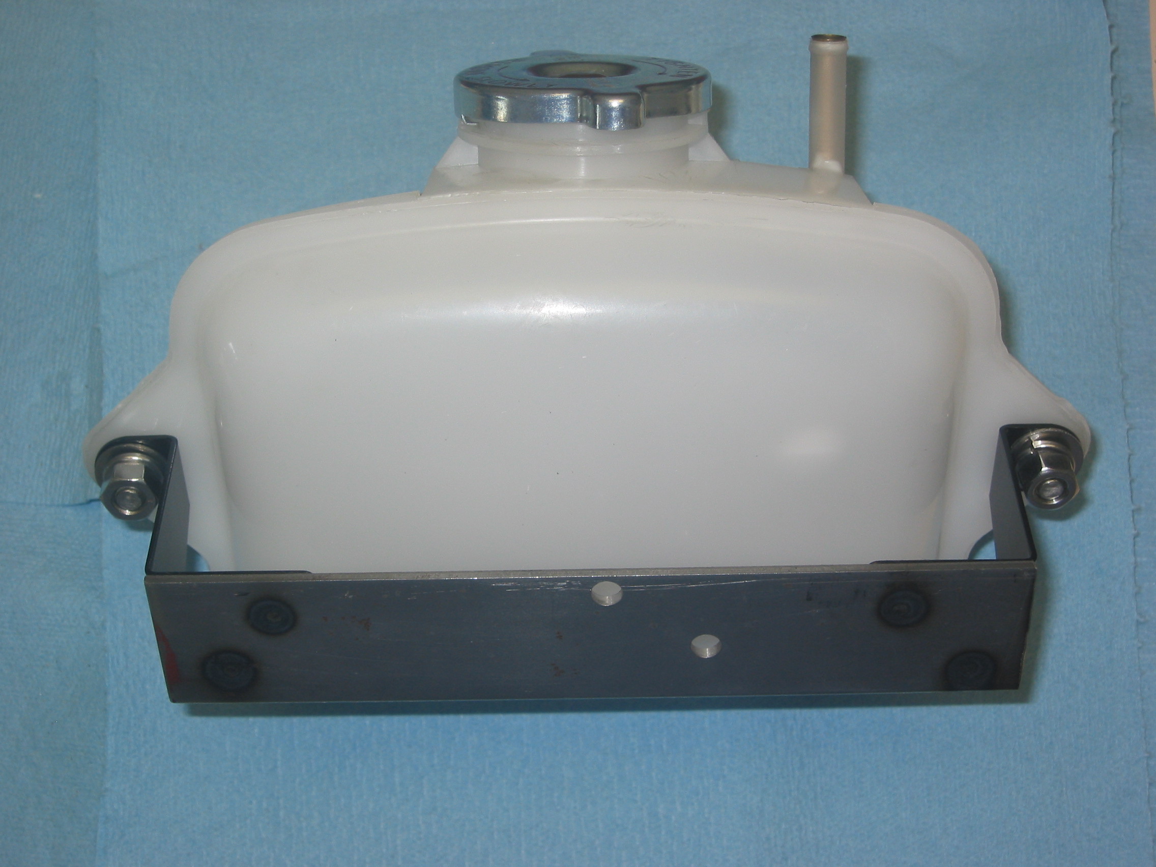
New Fuel Tank – Secured the new fuel tank with the two securing straps which I had slightly lengthened to make the fit better. The securing straps fastened to the rear boot wall with brackets and clevis pins.
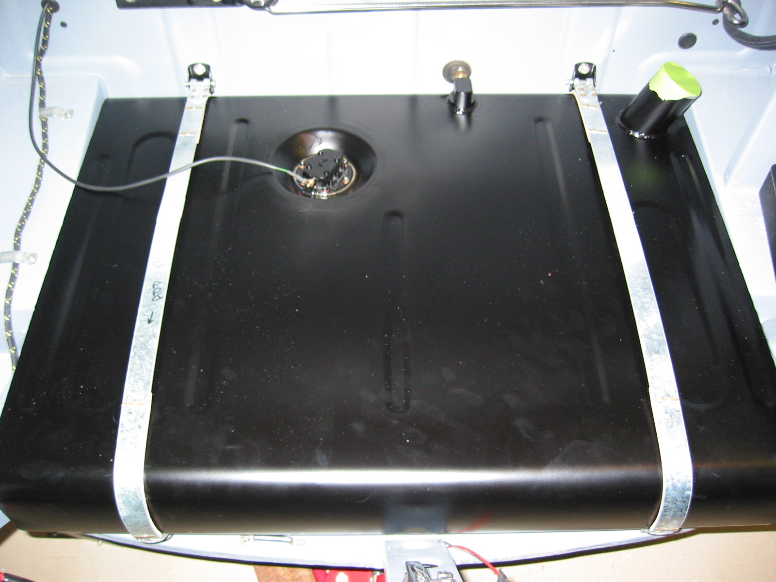
Aluminum Fuel Tank
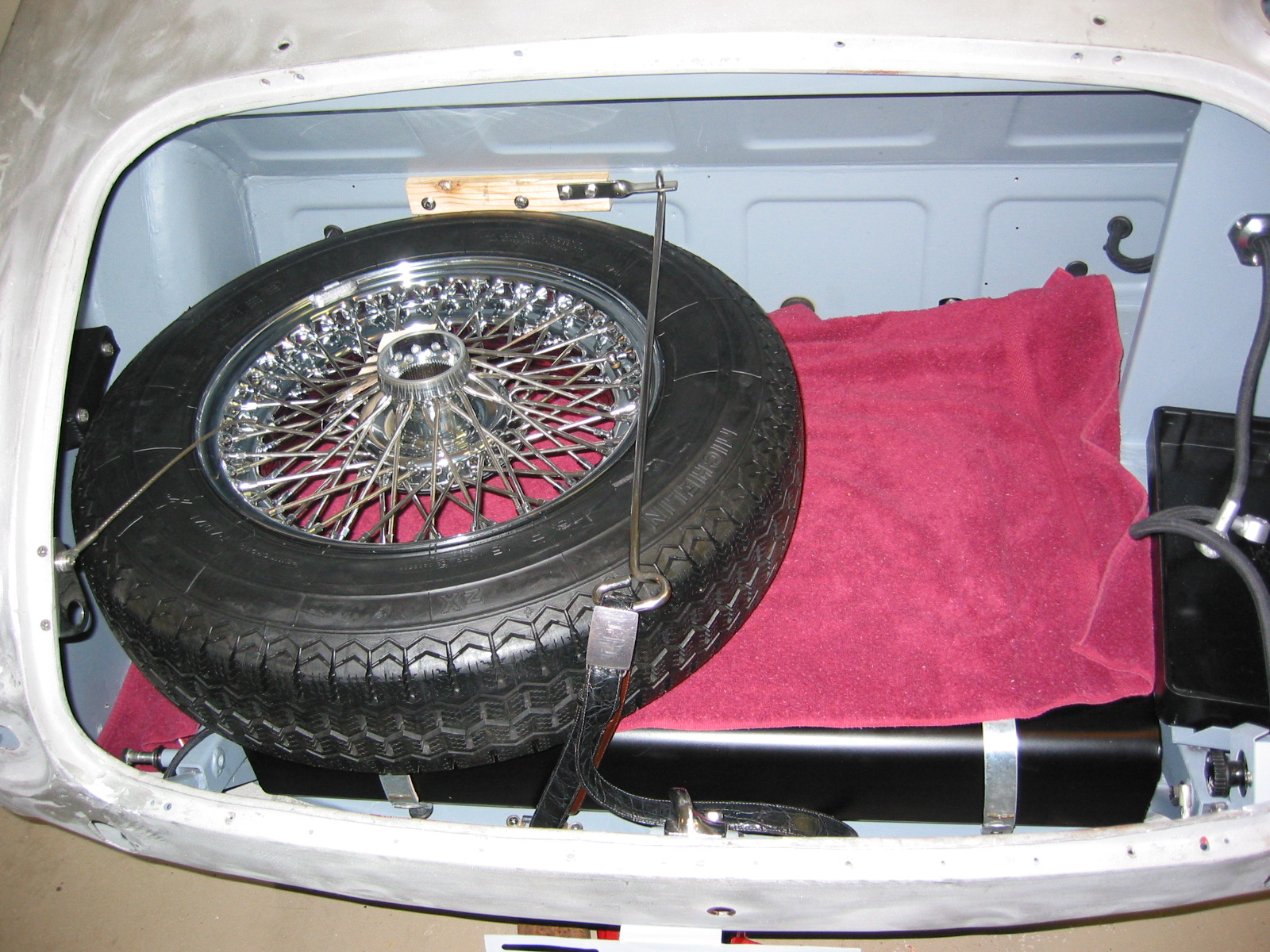
Spare tire fitment
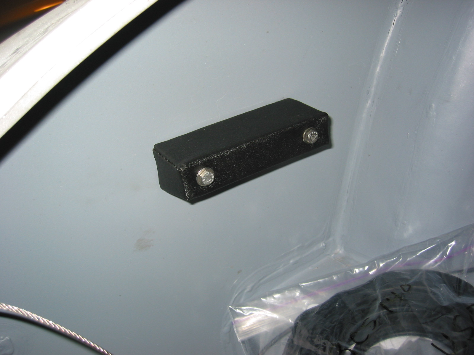
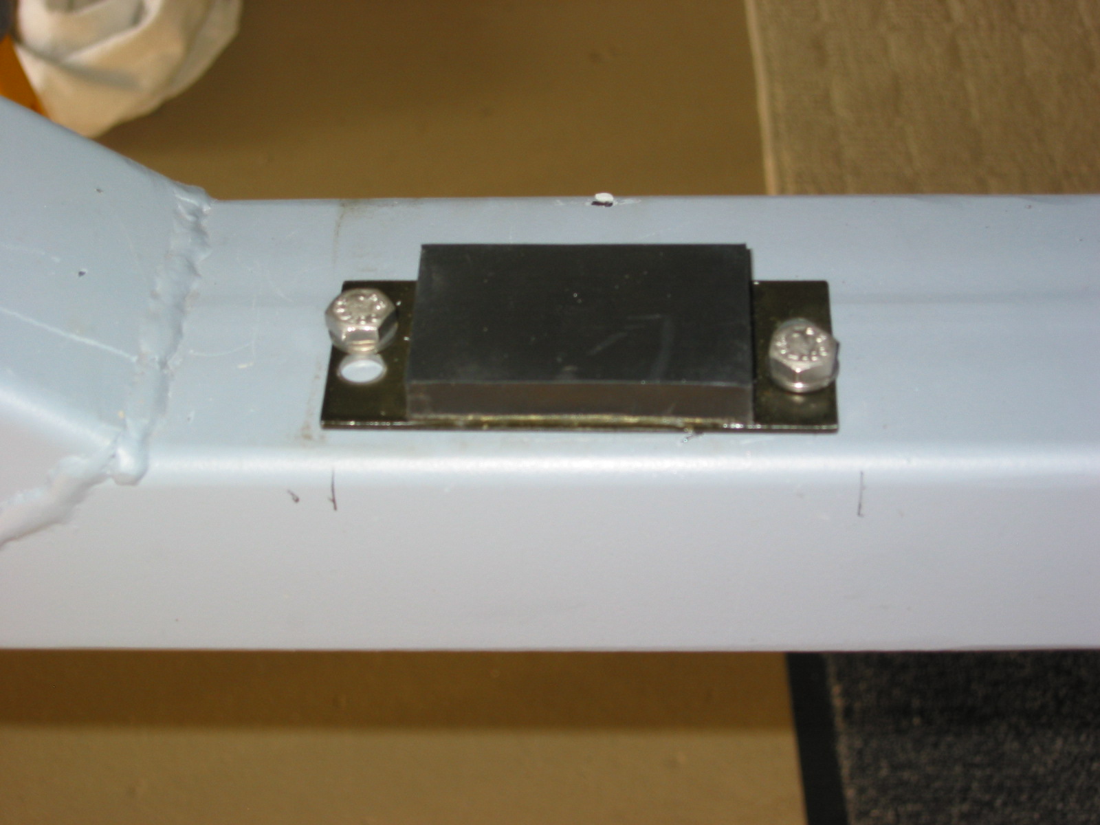
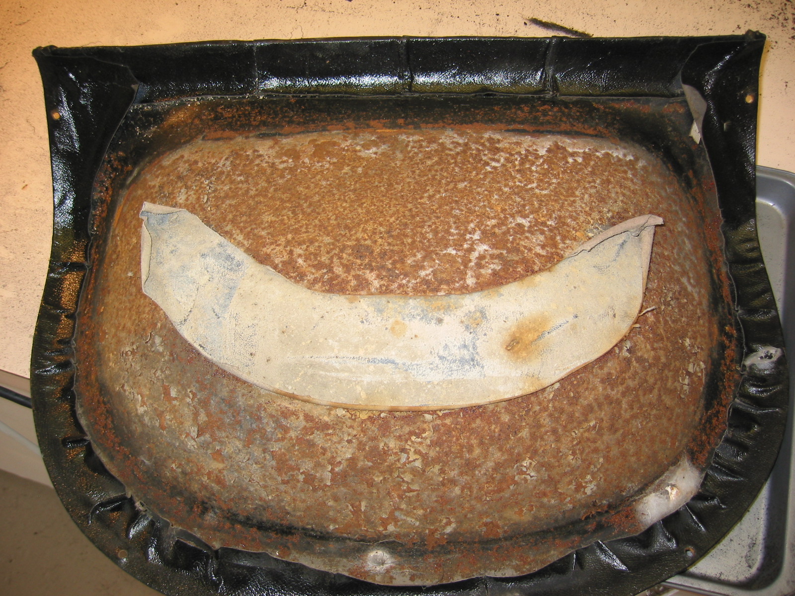
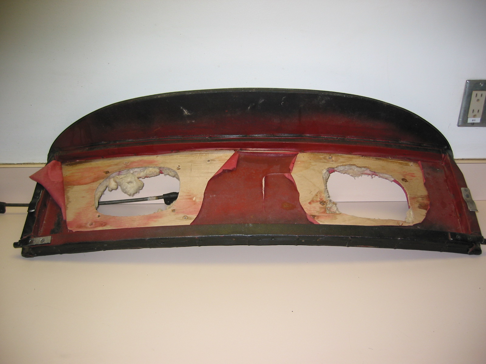
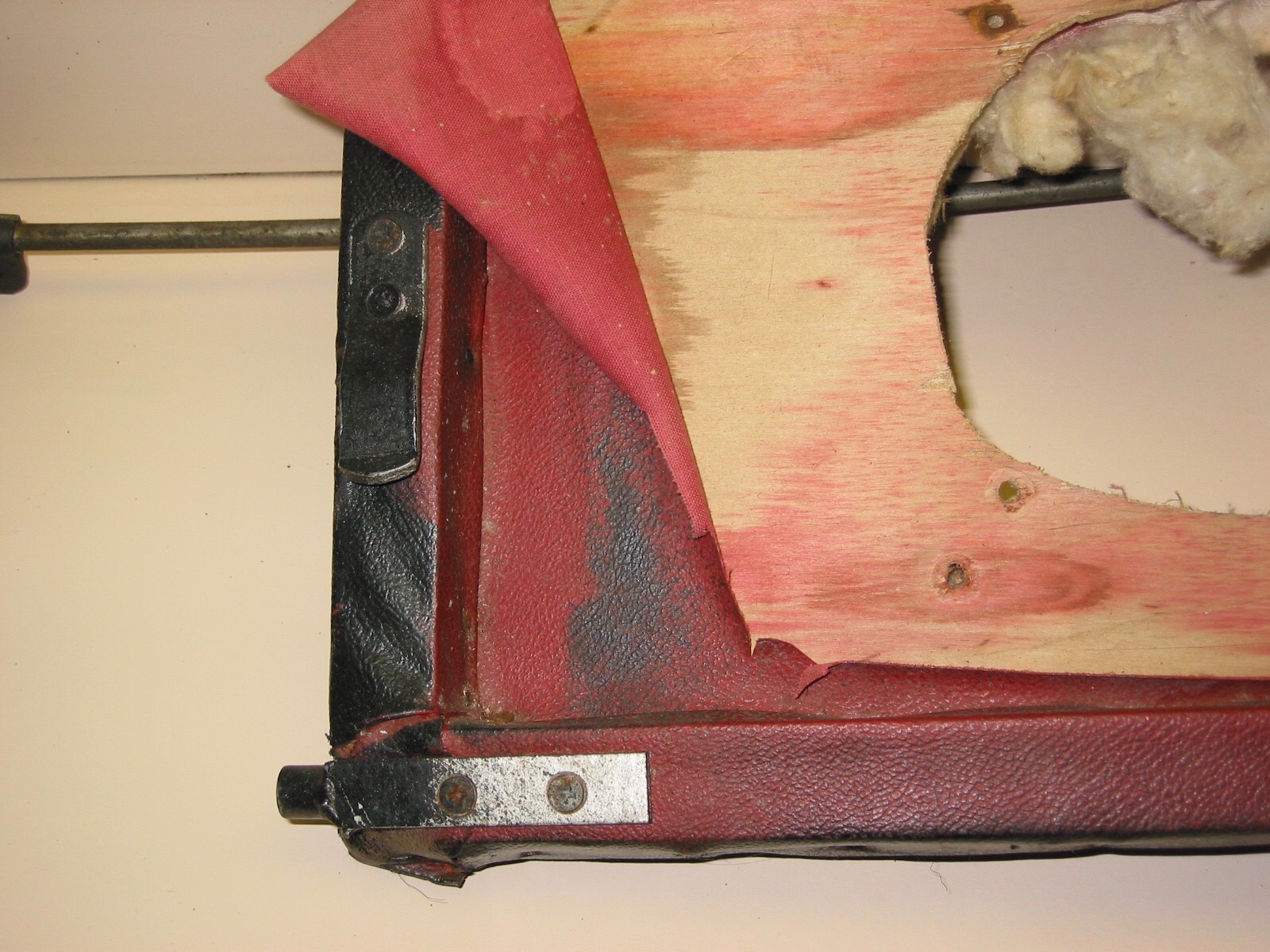
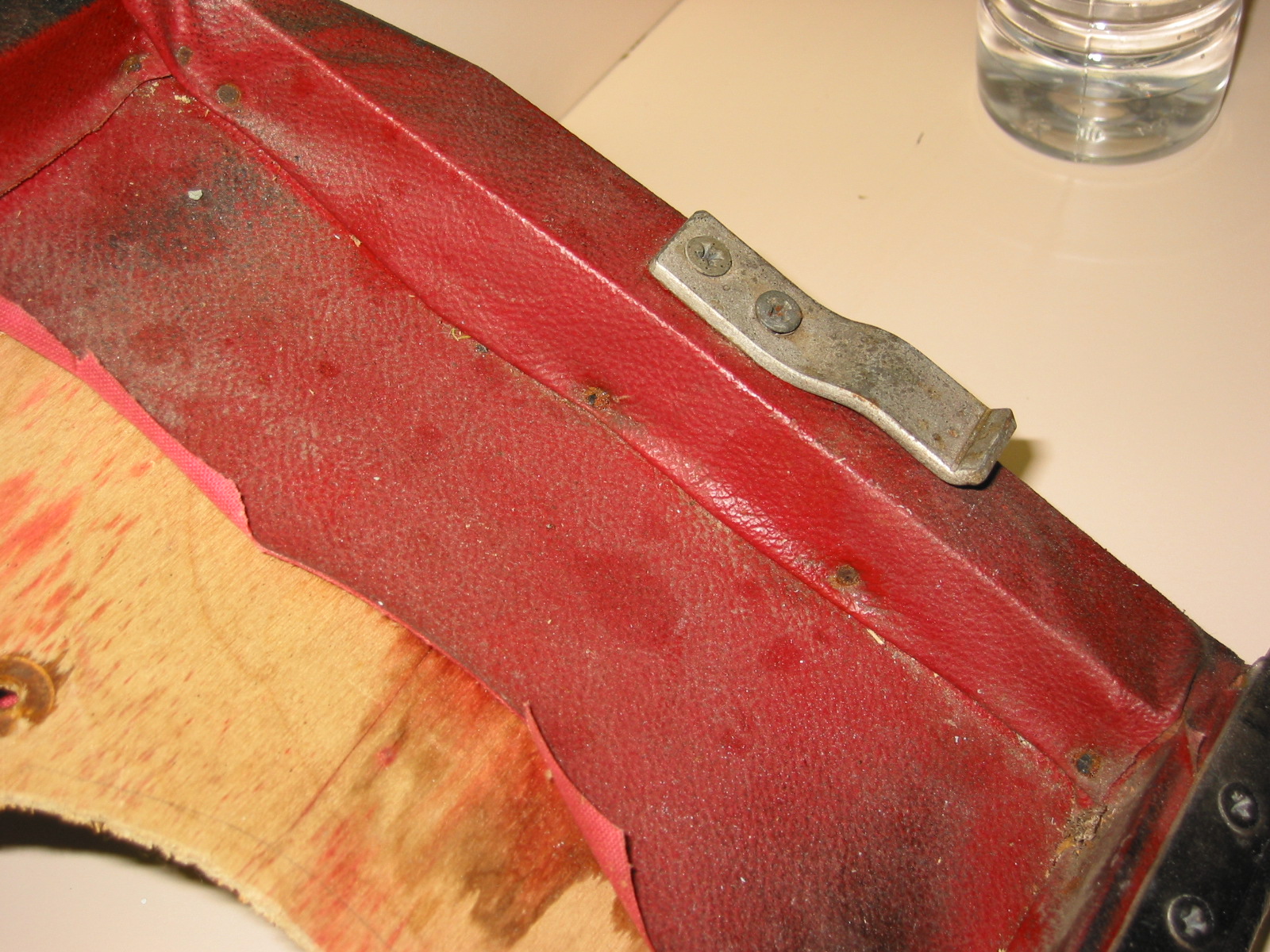
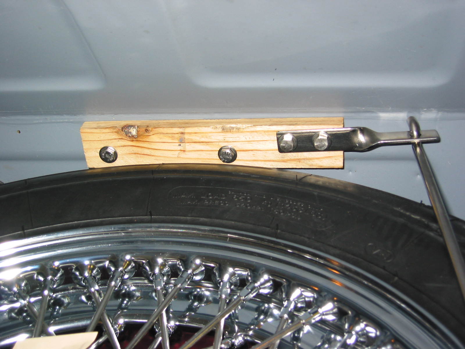
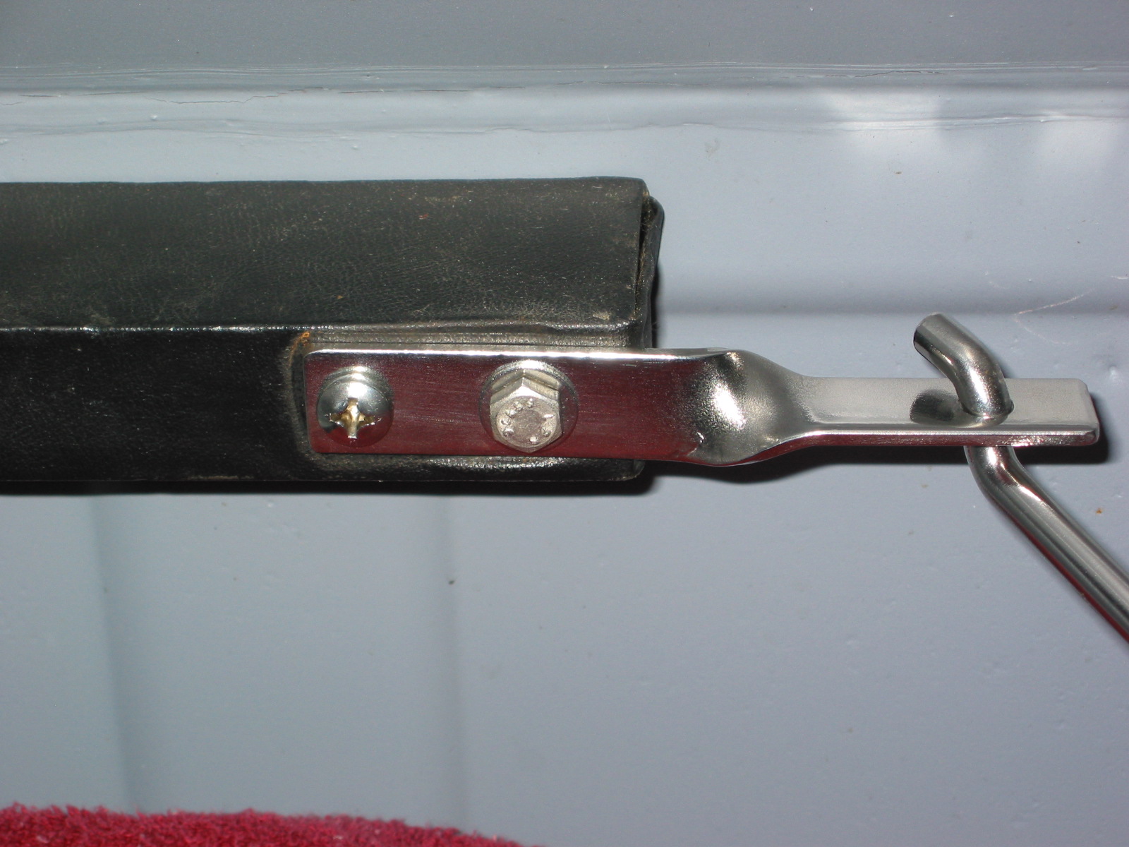
Spare Tire Block and Bracket – Installed the new stainless steel spare tire bracket and tie down bar. I had to make a new vinyl covered block to fit on the back boot wall to accommodate the higher spare tire and the slight rise that was “built in” by Martin Jansen. Turned out pretty well. I actually used old naugahyde from my original reupholstery work on the car 20+ years ago!
Spare tire bracket and block 1
spare tire bracket and block 2
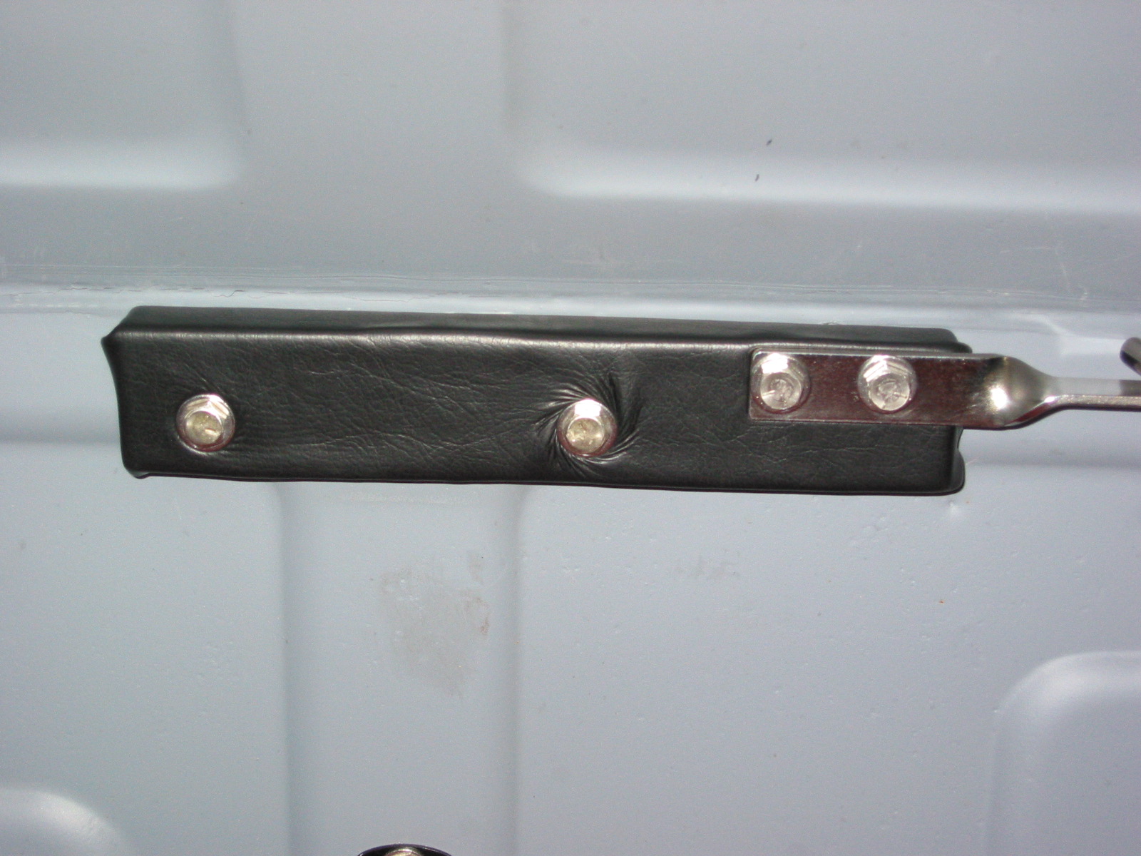
Spare Tire Block covering
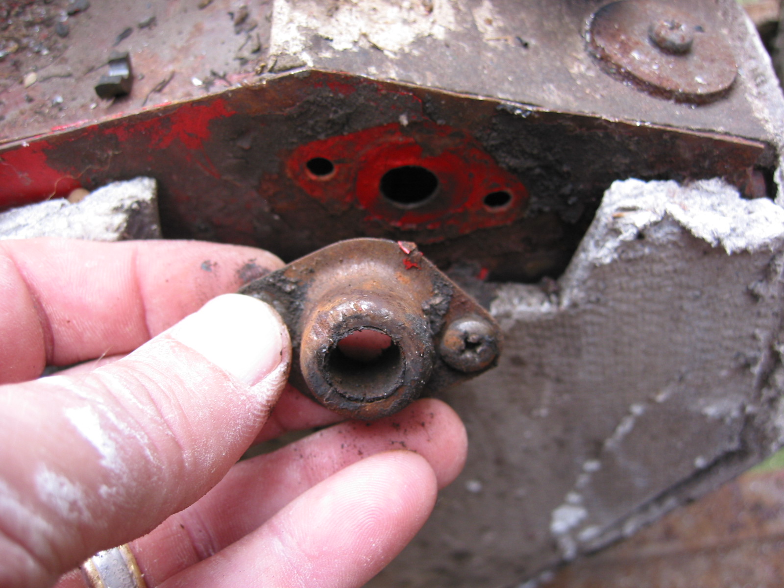
Fuel Filler Pipe – Installed the fuel pipe rubber gasket on the rear shroud. Lightly smeared Vaseline on the lower section of the fuel pipe and pushed it through the gasket into the boot. The Aston Cap is secured to the fuel tube with a threaded brass collar. David Nock advised that I should fasten the collar to the tube by reversing the ends and brazing the collar to the tube’s unfinished end. Then I cut off the old cap end to put into the rubber sleeve to connect to the tank neck.
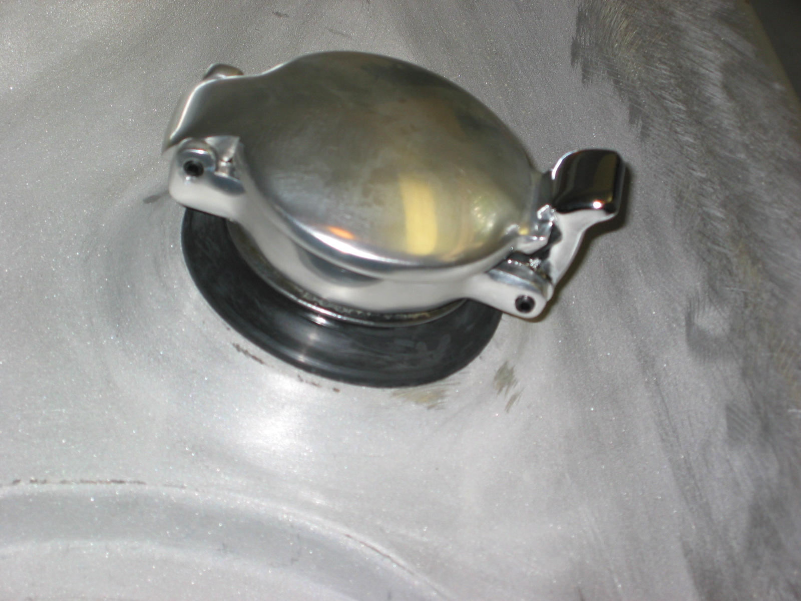
Aston filler Cap 1

Aston threaded collar

Fuel tube cut off
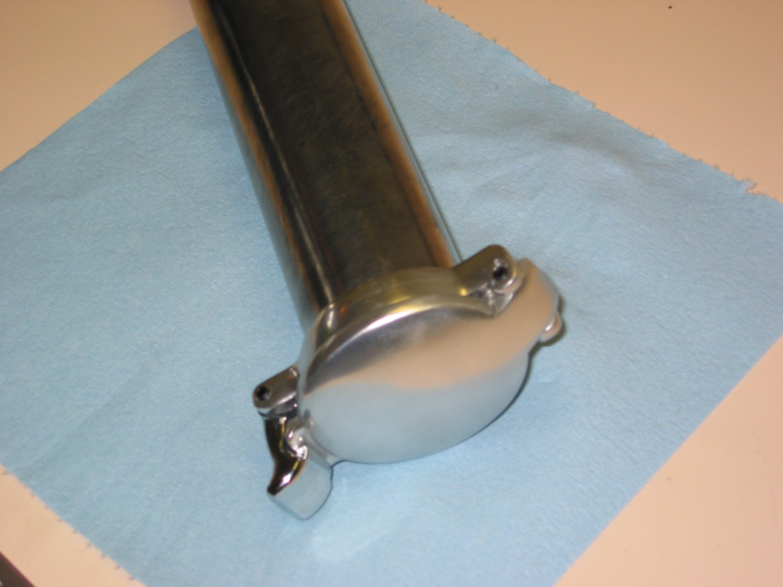
Aston fuel cap on pipe
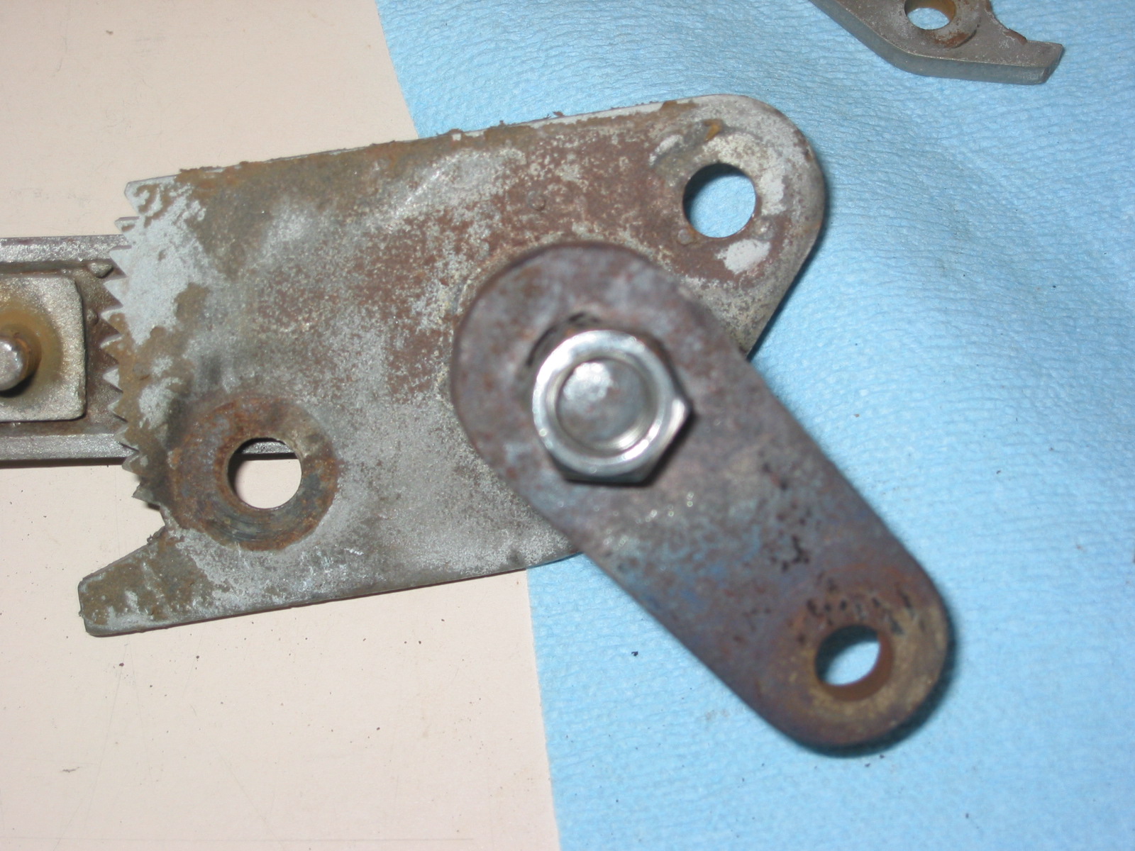
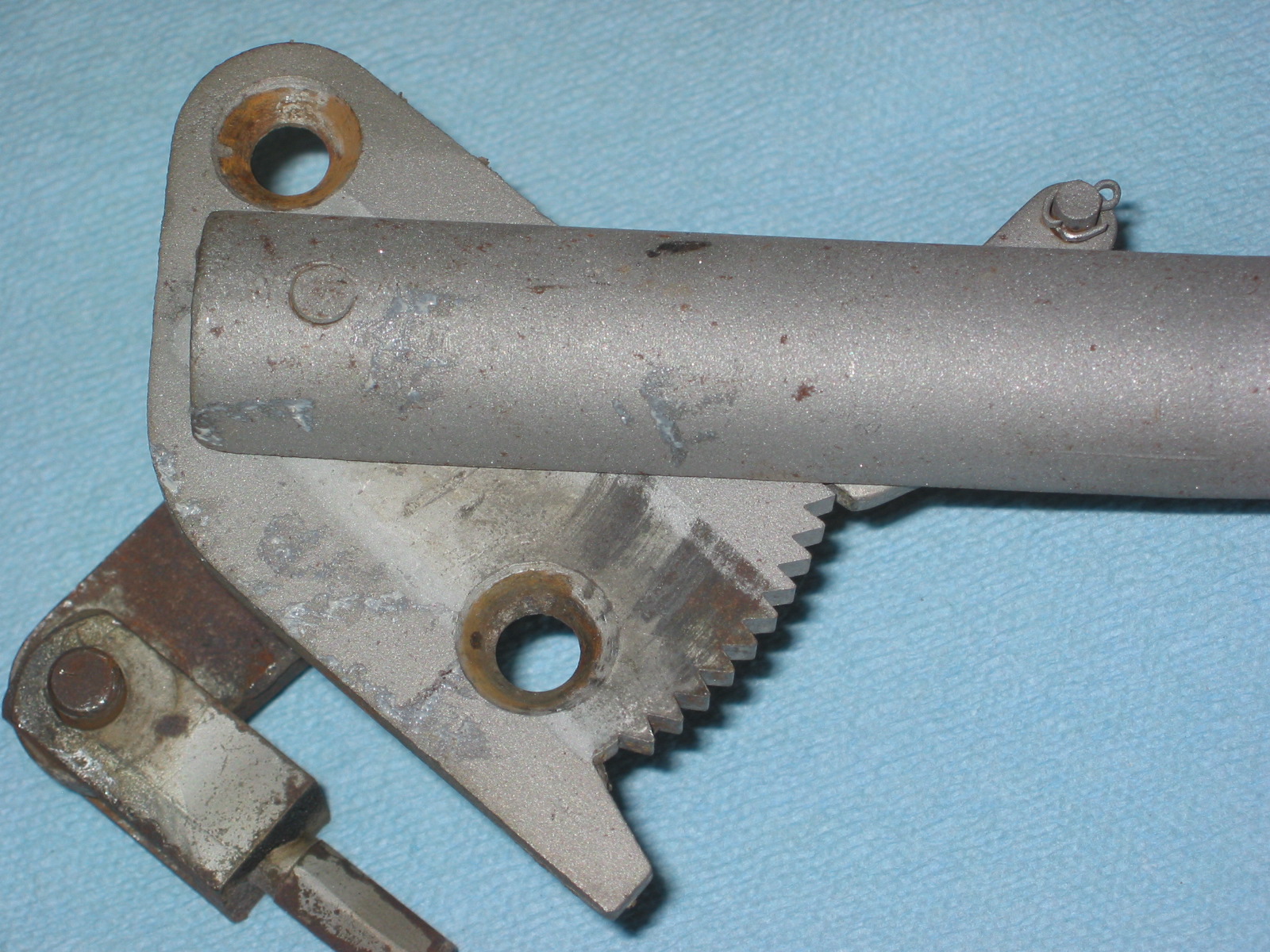
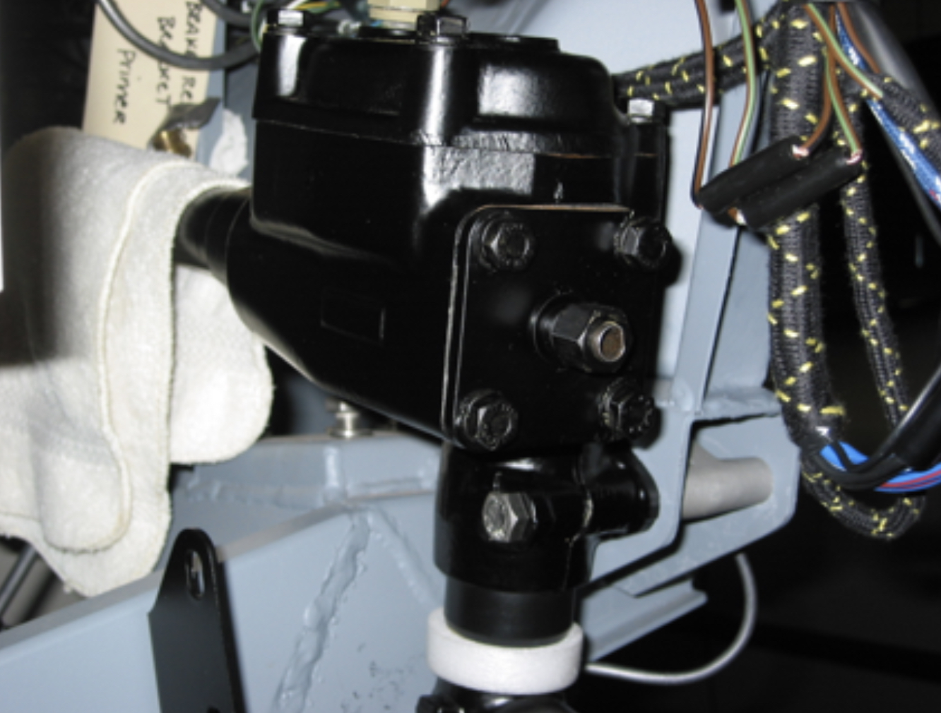
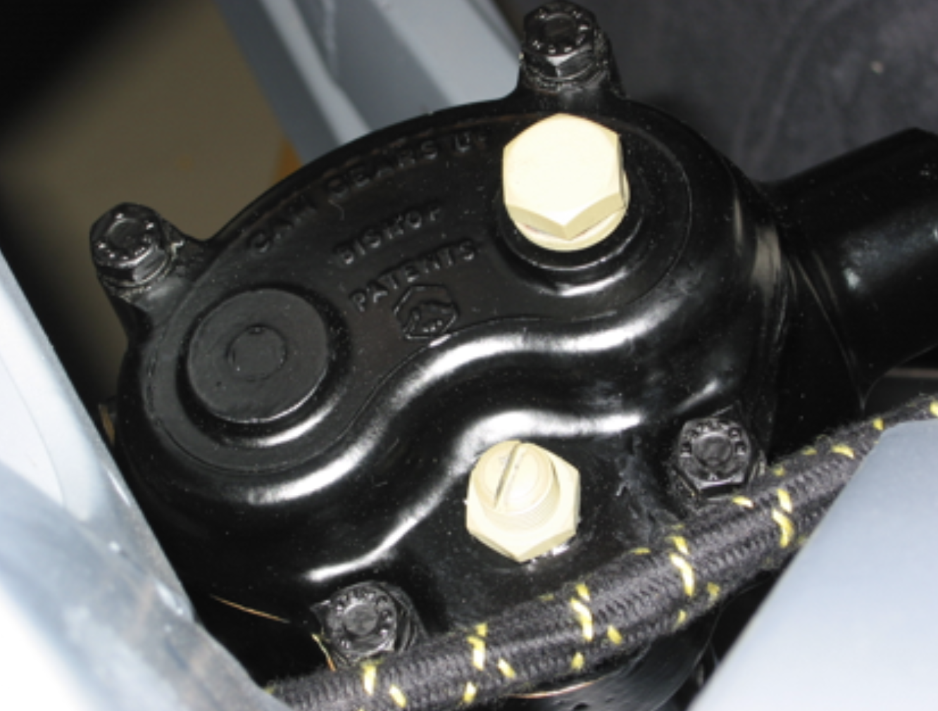
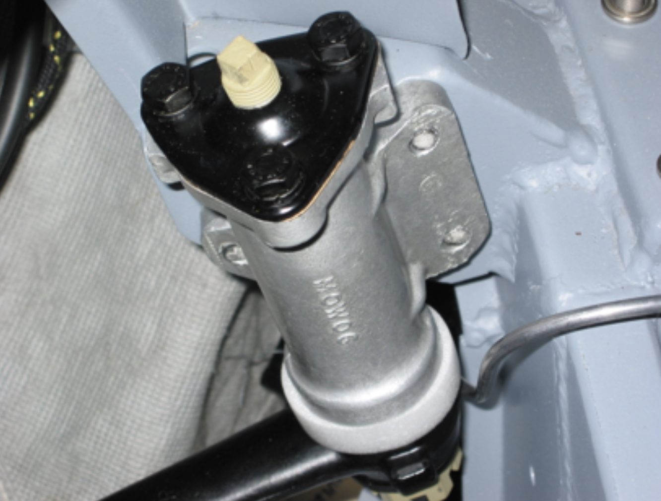
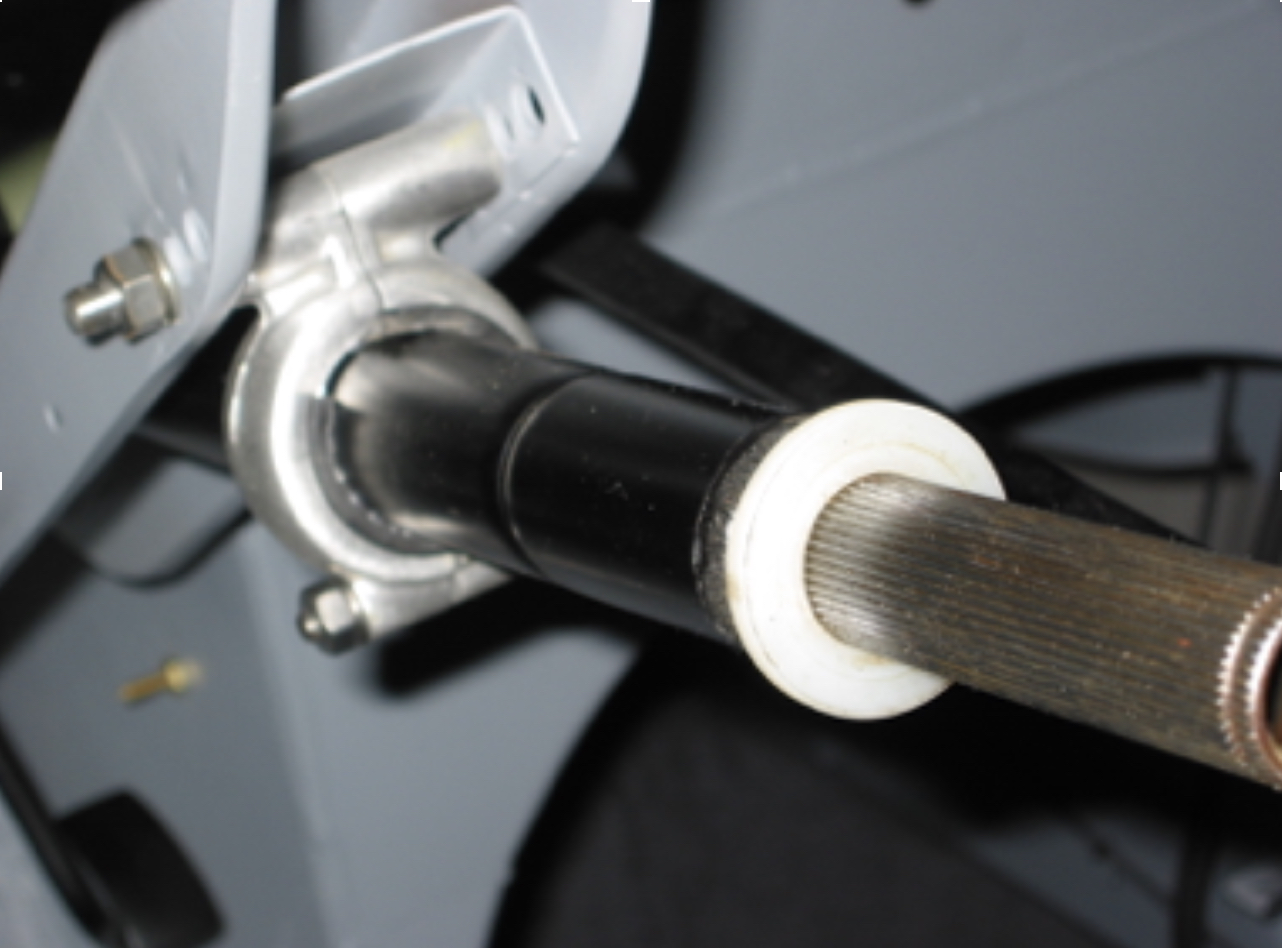
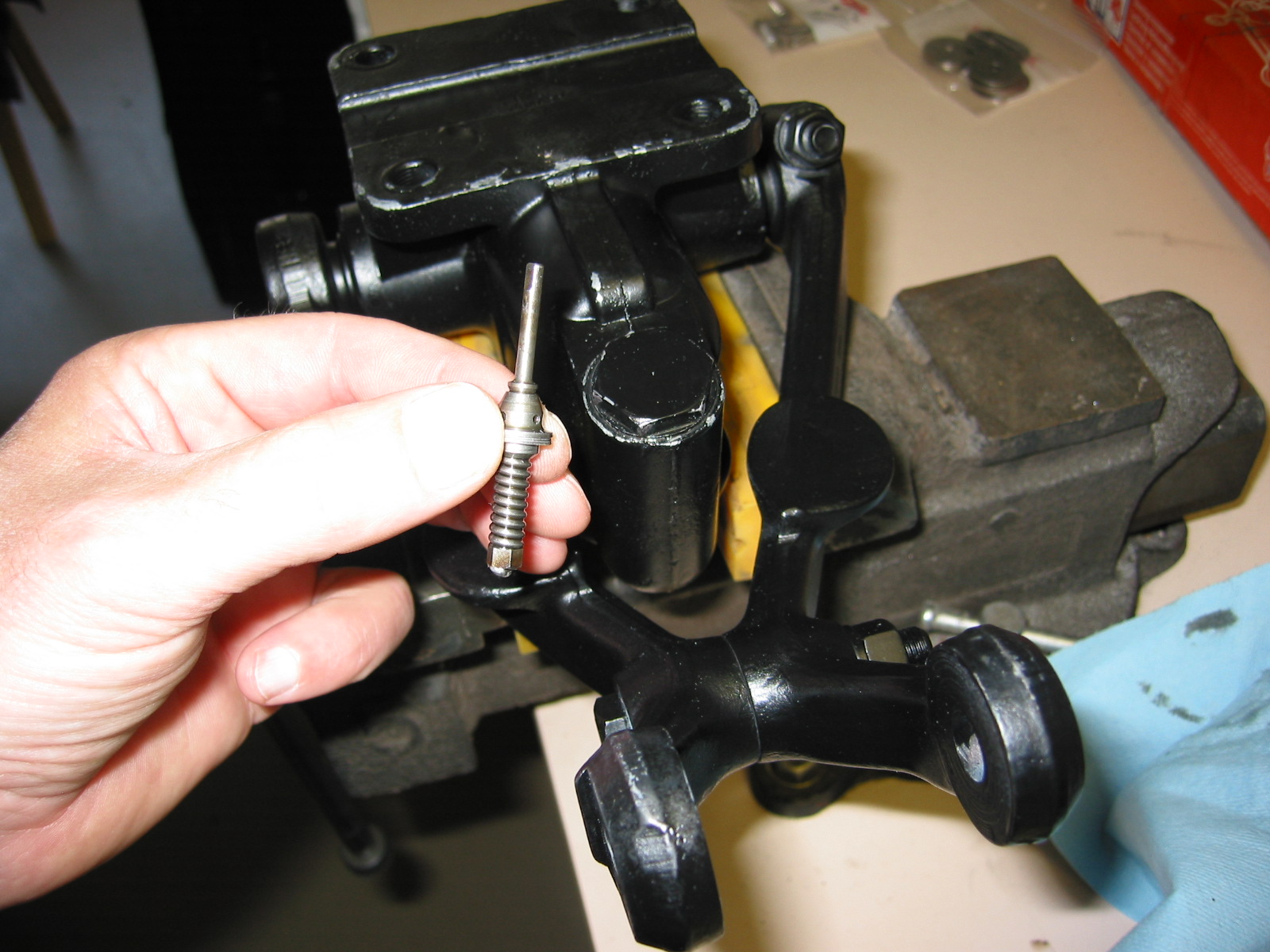
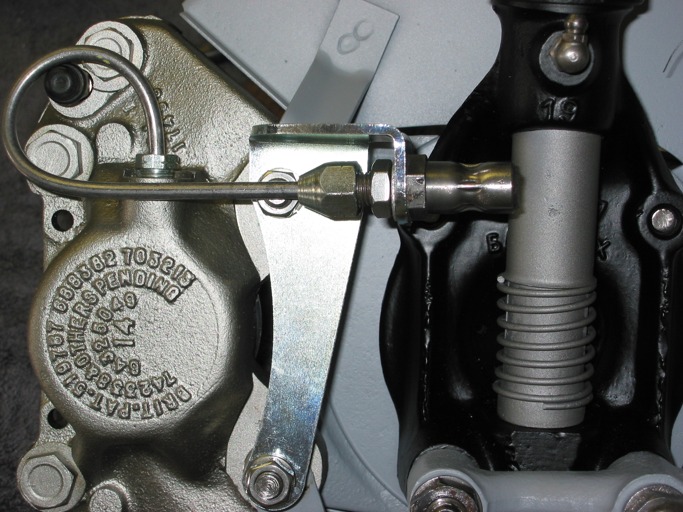
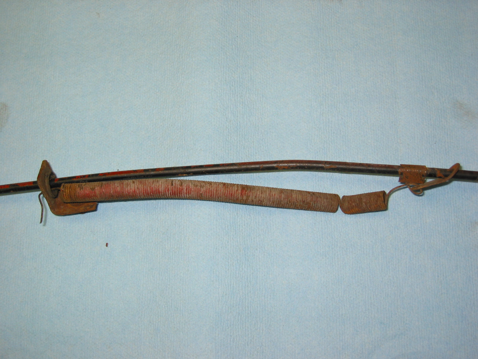
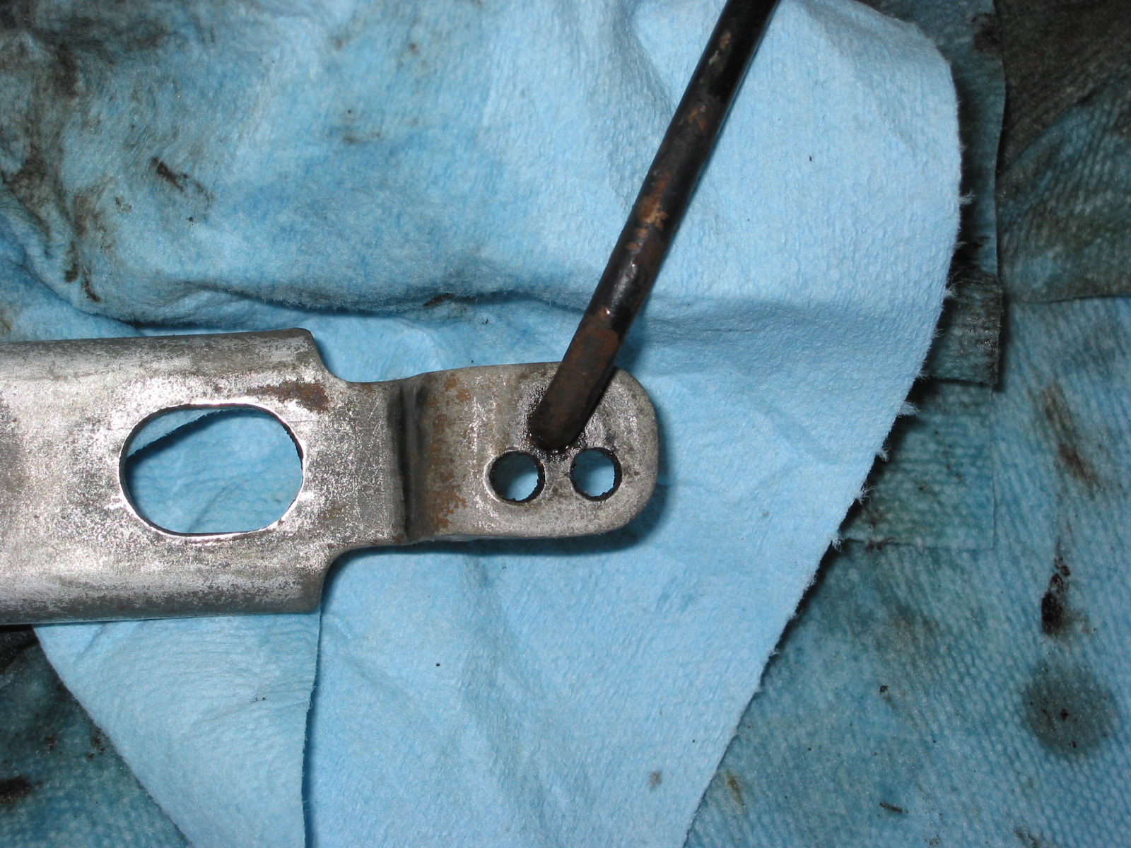
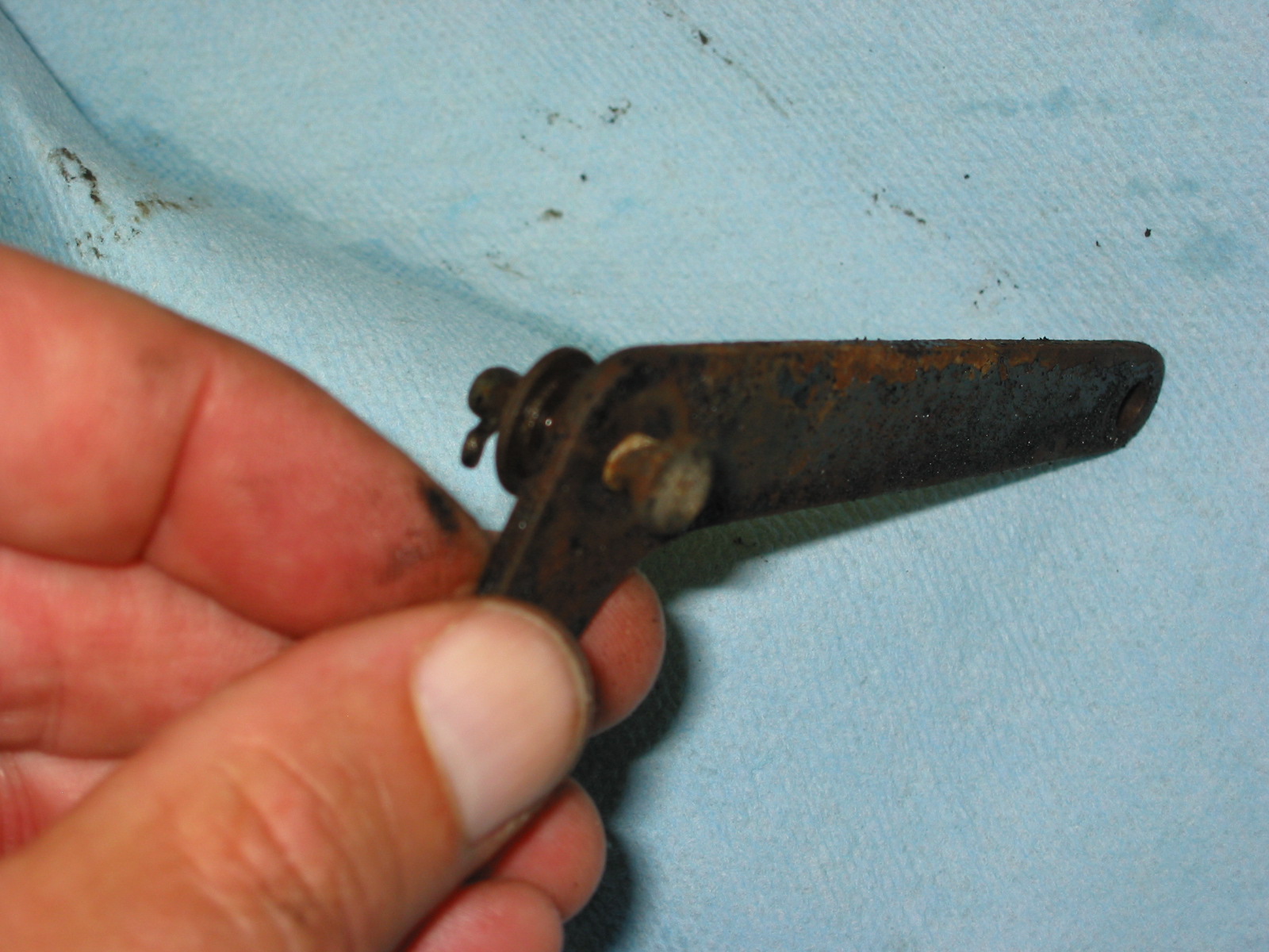
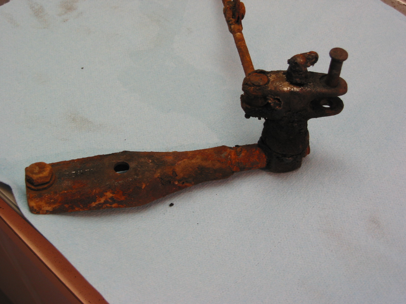
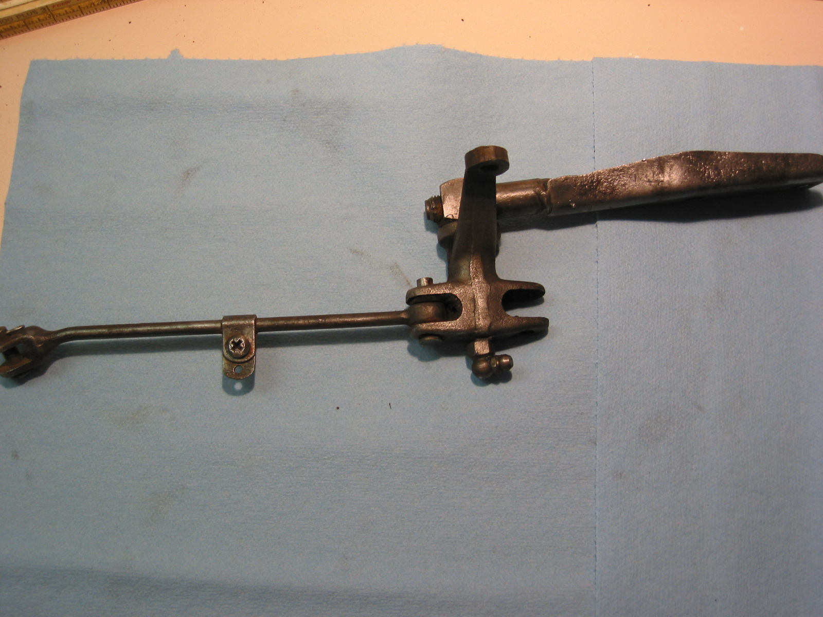
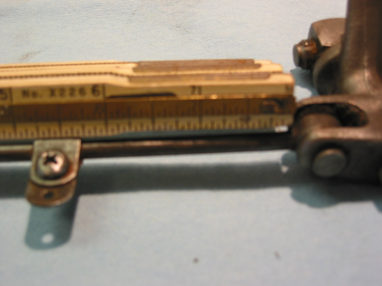
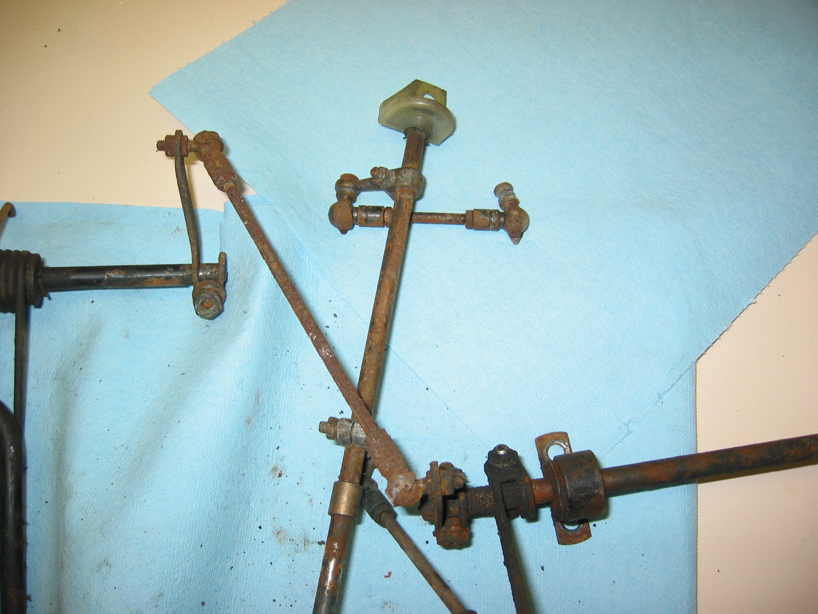
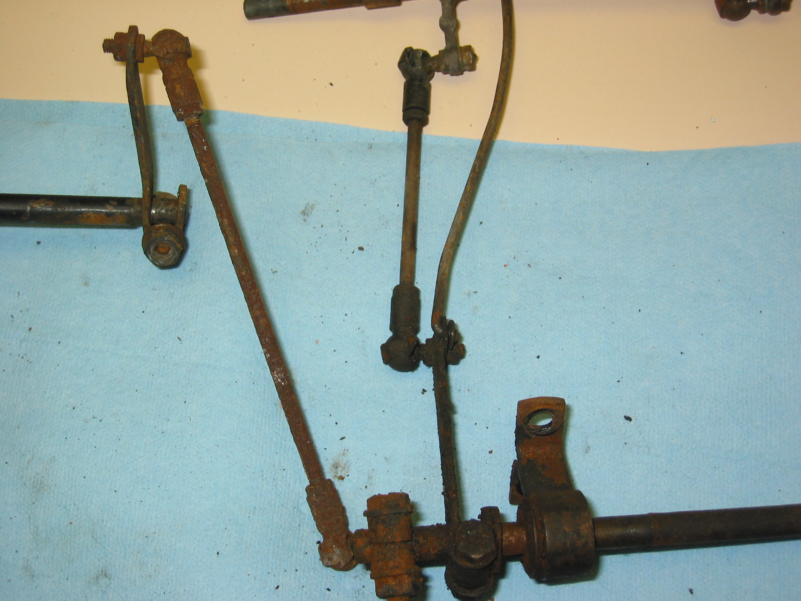
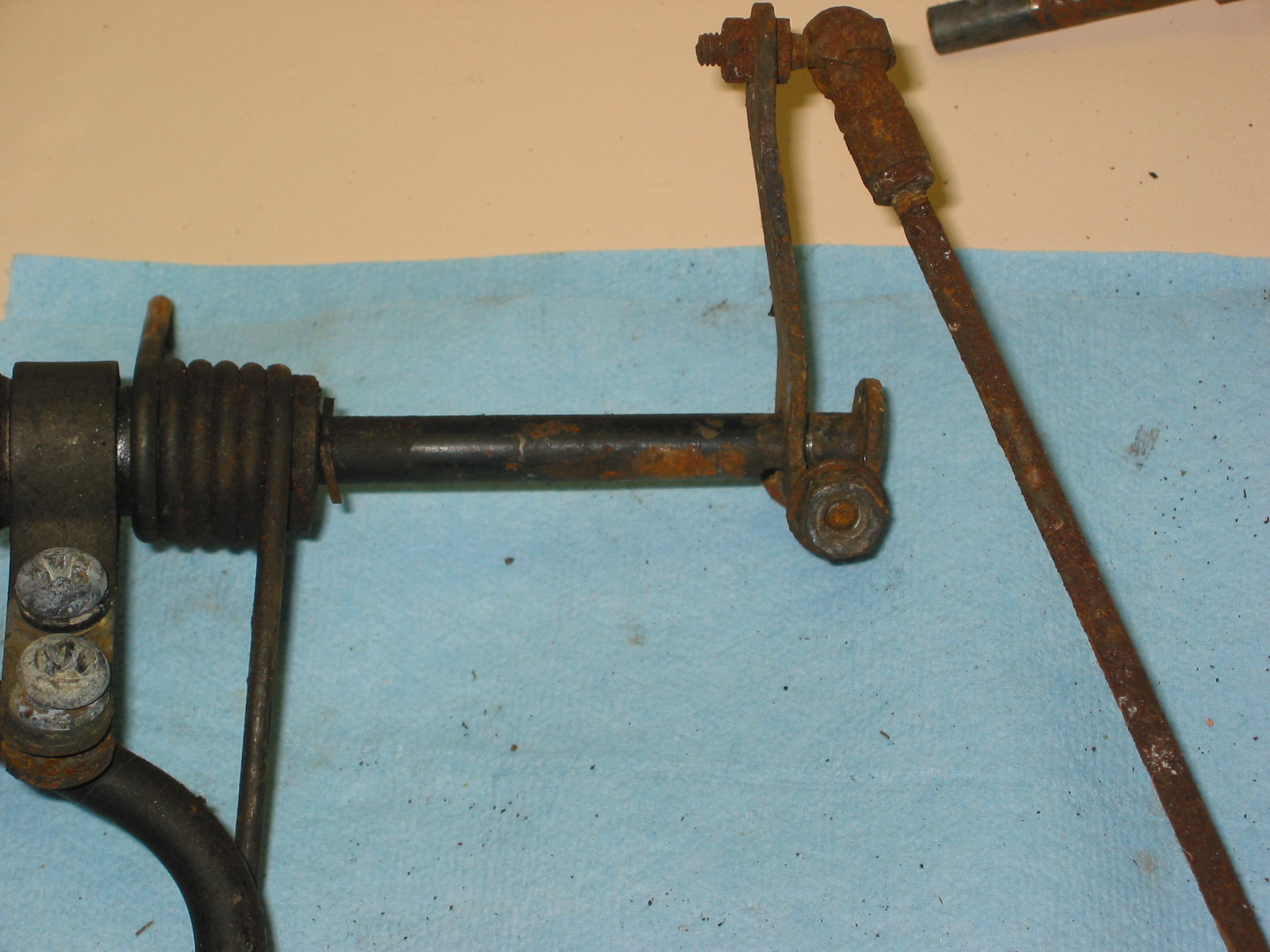
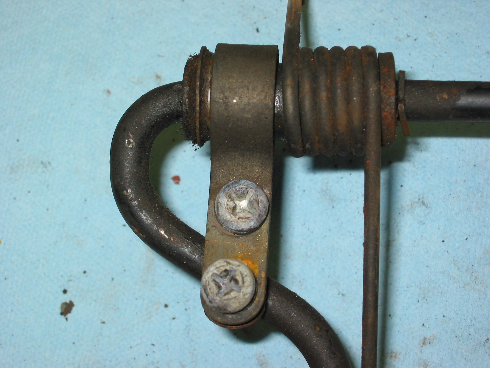
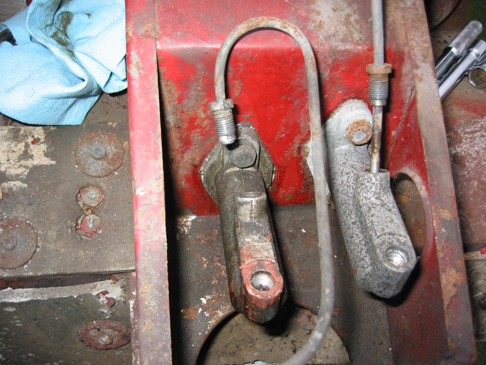
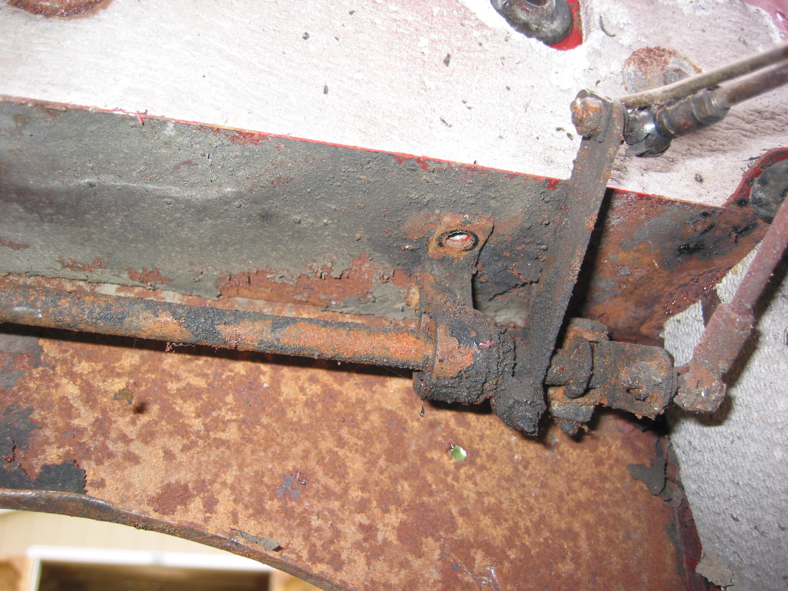
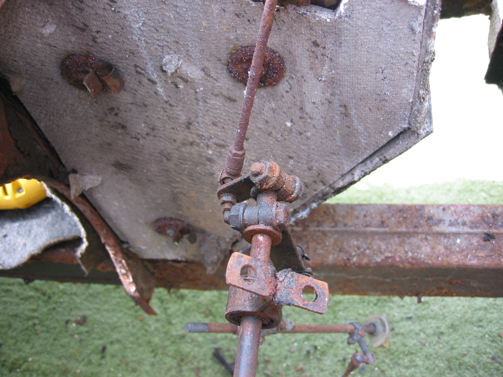
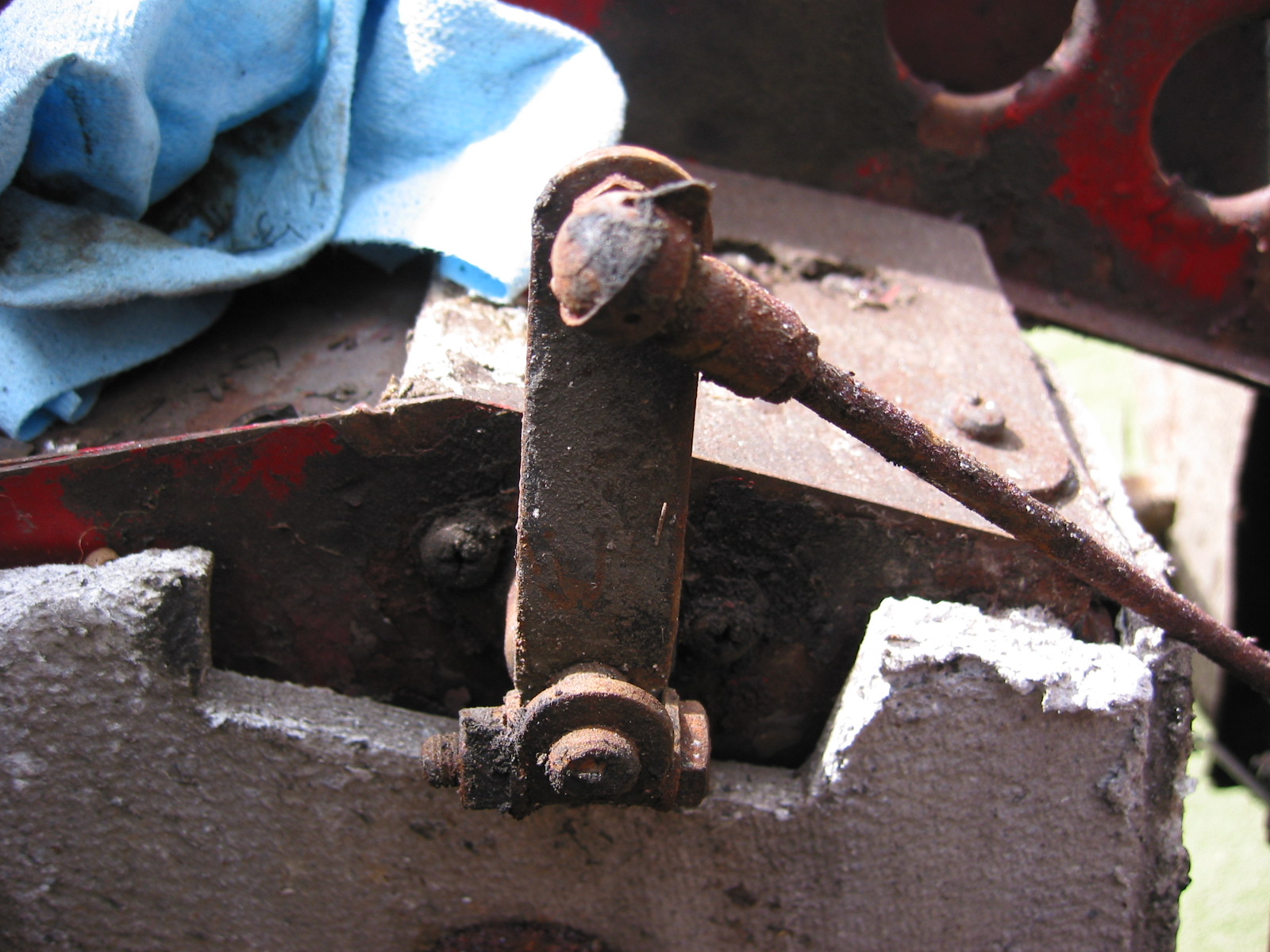
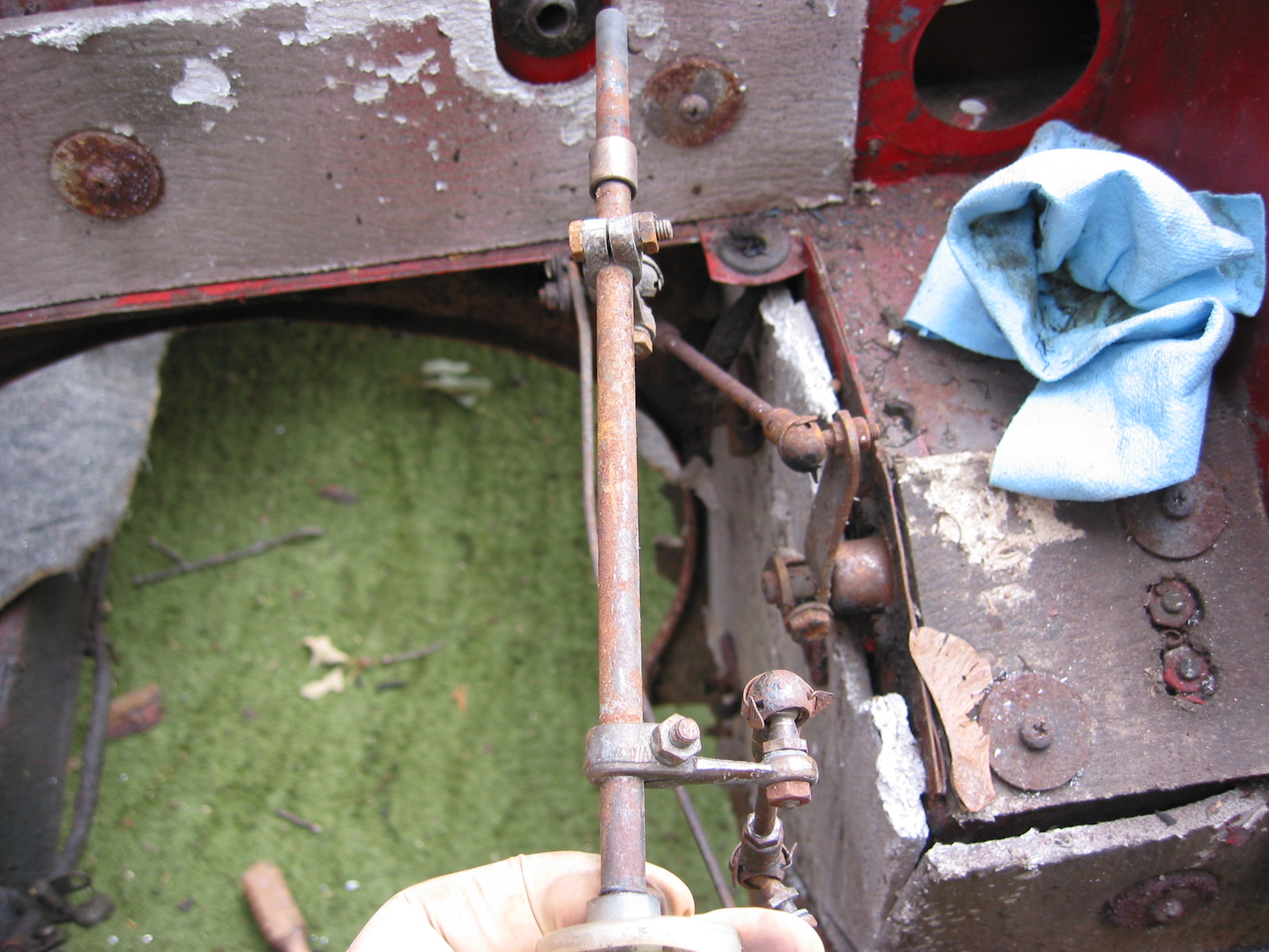
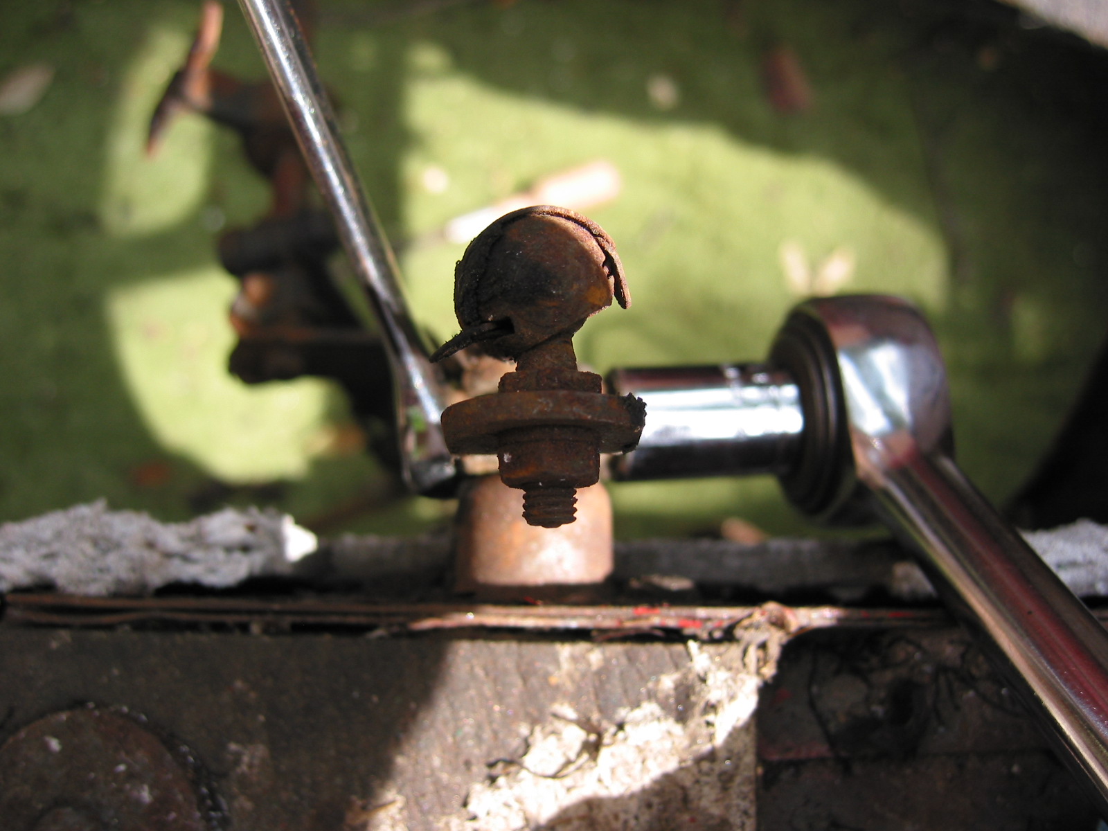
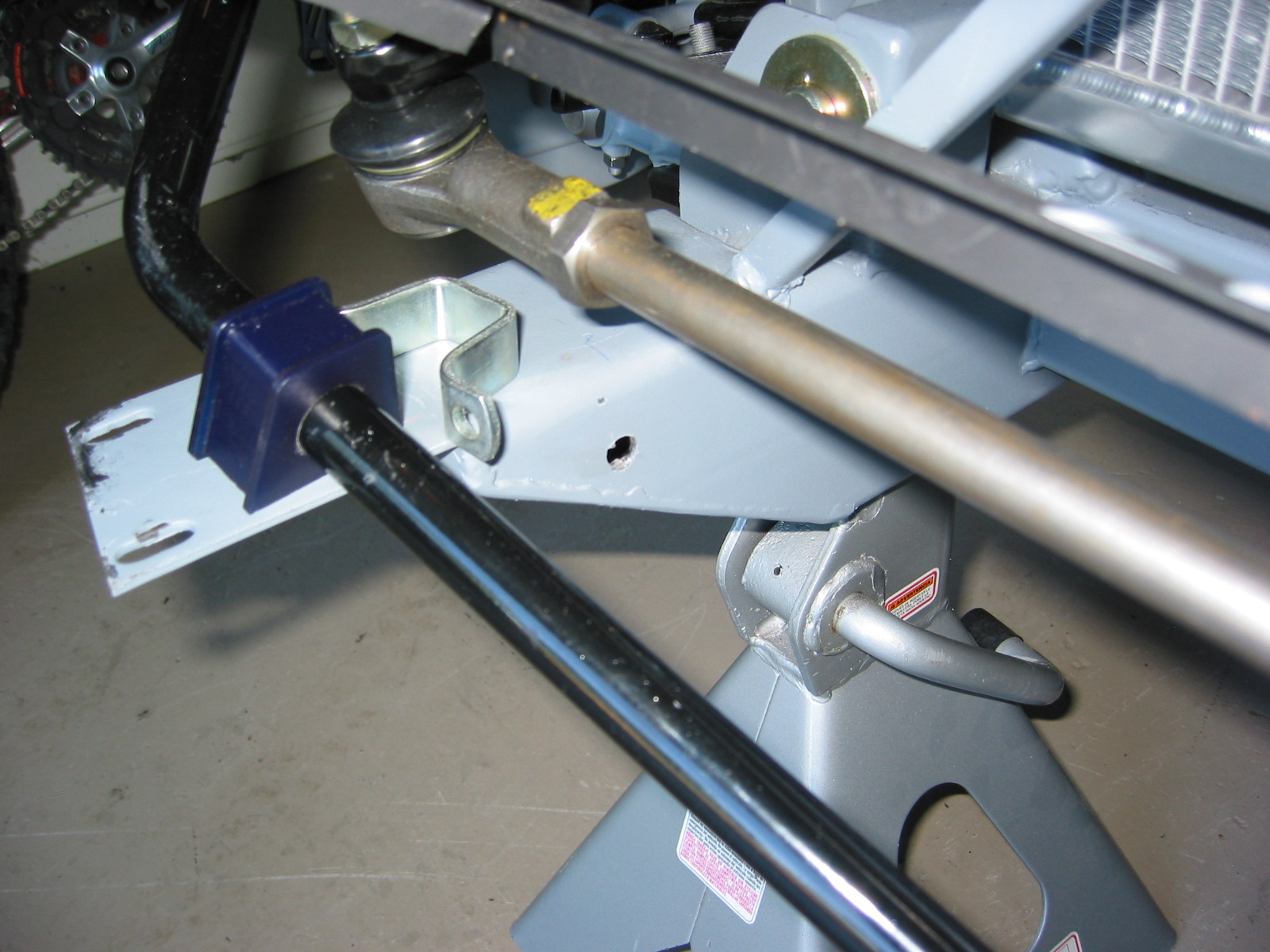
Steering Cross Bar – After discovering that the new cross bar for the steering was for a BJ8 I ordered new ends and installed the original cross rod. I probably could have used the BJ8 bar but it looked like the original provided a little more adjustment which I think I needed.
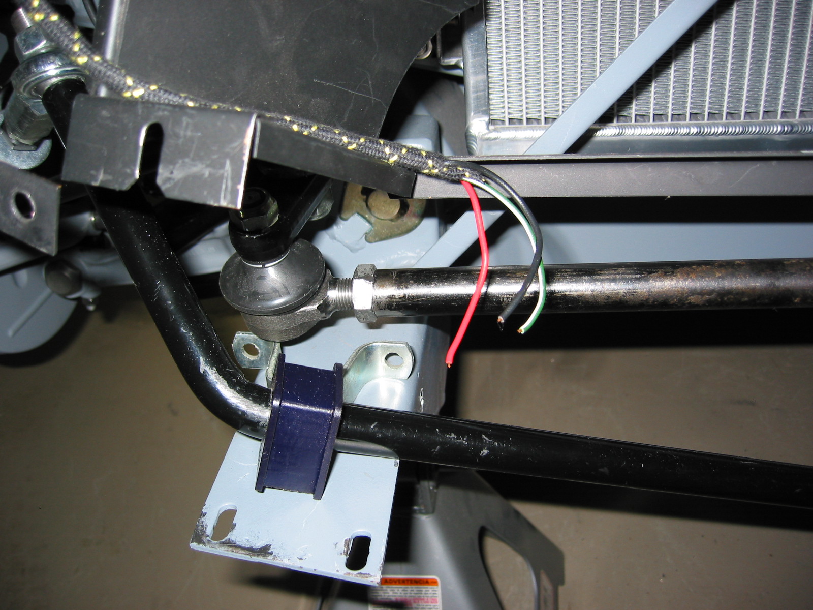
Cross rod right
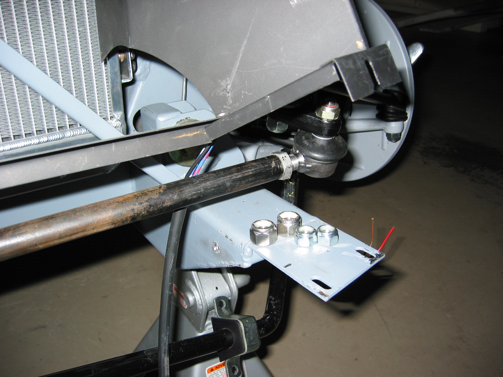
Cross rod left