About valv8988

Welcome to my website covering the history, restoration and “personalizations” to my small collection of classic cars. Feel free to email me with questions, suggestions and/or comments. I would love to have your feedback! Cheers, Lin Rose linwoodrose@me.com

Preparations for Engine Starting

Getting the engine and gearbox into the car was a big step in the restoration process, but there is still much to be done to get the engine ready to start and the car on the road.

In advance of the engine installation, we put together a check list of items associated with the engine/gearbox that needed to be accomplished. The list is in no particular order. As we completed items we gave ourselves a check mark and it was fun to see the checks start to add up as we got things done.

✅Remove Bonnet – struts and hinges.take the strut off first. before removing the bonnet hinges disconnect the Deutsch connector and the spade connector at the horn.

✅Jack Stands – place the car on jack stands.

✅Engine Hoist Leveler – Remove rocker cover and install leveler on engine.

Engine Mounts – Move rubber buffer from engine stand to the car mount.

✅Starter – Attach the power cable to the starter that will connect to the starter switch later in the process.

Battery Ground cable to firewall – disconnect during engine install.

✅Engine fan –  install six blade fan and spacer. Install fan belt and check tension.

✅Crossbar protector – put the custom-made sheet metal protector over the steering rack crossbar to avoid damaging the paint.

Remove fluids –  from engine, radiator and transmission –

✅Timing marks – make sure these are visible on the pulley before installing the engine.

Driveshaft Prop – Grease the yoke and the transmission splines.

✅Slave cylinder – check threads of the two mounting bolts, should be metric. The threads of the push rod extend beyond the arm by approximately one half inch (6-8 threads showing). The excess on the spacing shim goes to the front of the engine. Find the slightly shortened Allen key for the new cap screws.

Engine Mounts – Install the left-hand engine mount onto the chassis and leave it loose. Install the right hand engine mount onto the engine and leave it loose.

Header – Set the exhaust header in place so that it will be positioned to install once the engine is in place.

✅Engine/transmission install with engine hoist – Check to see if the heater plenum will require modification. Before the assembly is all the way home push the driveshaft yoke into the rear of the transmission.

✅Transmission mount – install the ⅜” – 24 x 3 ½” bolts through the chassis and into the mount and tighten. Next, tighten the front engine mounts.

✅Now center the transmission in the rear mount and tighten the transmission pad mounts.

✅Install the bolts in the sides of the rear mounts from the inside of the car with the self locking nuts inside the tunnel. It may be helpful to tape the nuts in the wrench to make starting the threads easier.

✅RadiatorIt is a little tricky to install. It works best to begin with the upper right (passenger side of the car) mounting point first, then the lower right, followed by the upper left mount and finally the lower left mount. 

✅Radiator hoses – connect and clamp

✅Overflow coolant tank – determine right place for the overflow tank drain line and install a fitting in hose. Connect the radiator overflow to the tank.

✅Alternator – connect the wiring for the alternator.

✅Vacuum pipe – connect the vacuum hose from the distributor to the carburetor.

✅Starter – attach the power cable from the starter to the starter switch.

✅Ignition Coil – attach the wiring to the coil and distributor. Connect the high tension line from the distributor.

✅Oil pressure gauge pipe/hose – connect to engine.

✅Water temperature gauge – connect capillary tube two cylinder head.

✅Heater hose from cylinder head water valve to heater – uses two 10-22 mm jubilee hose clips

✅Heater hose from heater box to copper pipe – 

✅Rocker Cover – install the rocker cover.

✅Breather hose – connect the hoses and clamp

✅Driveshaft – connect and tighten bolts/nuts.

✅Refill fluids in engine, radiator and transmission – transmission requires 2 ¼ pints of Redline MT-90.

✅Remote clutch bleeder valve – connect the remote bleeder stainless steel flexible hose to the bracket on the left side of the heater box.

✅Clutch – Bleed the clutch master and then the slave cylinder. To eliminate all air, the slave cylinder piston should be held in the fully retracted position while bleeding. Do this by running out the adjustable push rod until it is pushing firmly on the clutch fork. Keep the master cylinder reservoir topped up while slowly and gently pumping the clutch size cylinder Into operating position. A power bleeder works well here.

Adjust the push rod length to give some free travel at the clutch pedal. Assure clutch is releasing fully while the vehicle is still up on jack stands. Confirm free play assuring that you can move the clutch operating lever away from the clutch slave cylinder push rod. Finger pressure against the lever should be able to move it against the pressure of the spring inside the Bell housing. Generally 1/4 inch to 1/2 inch of free play measured at the fork will be adequate. Be aware that the clutch pressure plate can be over traveled. If the clutch releases when the pedal is partway down, but then seems to reengage at full pedal down. It is being over traveled. Add free play until this condition disappears.

https://youtu.be/k11eIyfErMY?si=YUO94N5qavN61VFl

✅Battery ground cable to firewall – reattach.

✅Ground Strap – Attach engine to frame

✅Electric Radiator “Pusher” Fan – see Moss Motors site for directions: https://mossmotors.com/media/instructions/231-658.pdf

✅Intake and Exhaust Manifolds with gasket 

✅Carburetor –  install heat shield, phenolic spacer, gaskets, choke and accelerator cable. Connect fuel hose from pipe to carb. Connect the float bowl overflow hose. Connect the breather hose from the timing chain cover canister to the carb. Connect vacuum hose to distributor. Put ATF in the carb piston. 

✅K&N Air Cleaner – Install and spray with special oil.

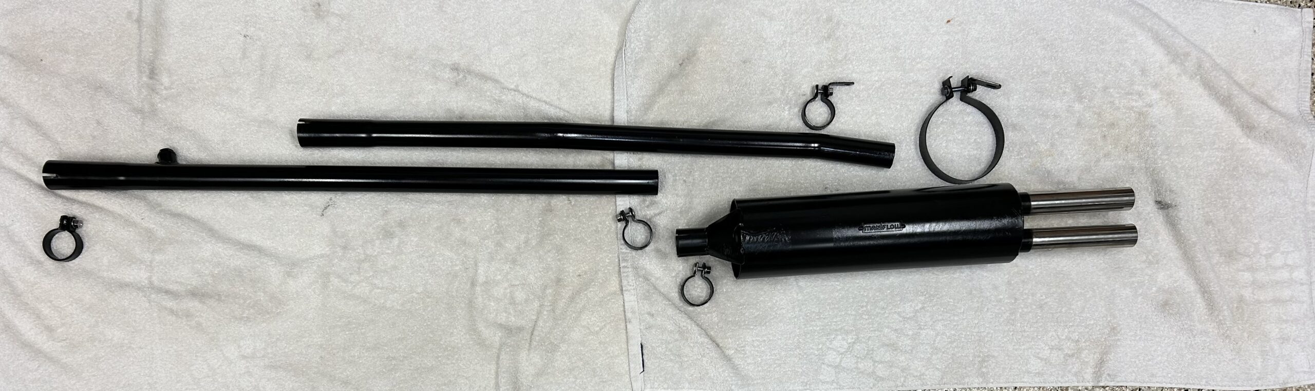
✅Exhaust system – install, exhaust header, exhaust pipes, and muffler.

✅AFR gauge – connect gauge to the O2 sensor and power.

✅Gasoline – partially fill fuel tank with gasoline.

Start engine!

Our first step was to install the ground strap that connects the chassis to the engine/gearbox. The strap we used was sourced from Moss Motors. We actually connected the strap to the starter motor bolt that secures the starter to the engine backplate as it is important to have a strong ground connection for the electrical draw of the starter. As with most things in this post, the details are in the Bugeye Restoration Video Episode One Hundred-three.

Ground Strap from chassis to Engine

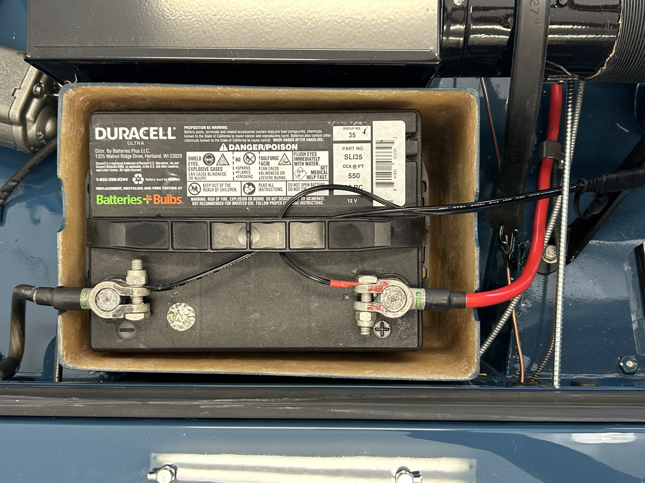
Our next item was to install the starter motor power cable from the battery post of the starter switch to the starter motor terminal.

We then installed the oil pressure gauge pipe and hose from the gauge to the fitting on the right side of the engine block. Originally this arrangement was just copper pipe but we used a copper fitting and hose supplied by Bugeyeguys. Copper, when it gets old, also becomes brittle and can be subject to breaking and leaking. The rubber hose used in the kit helps to absorb vibration.

Oil Pressure Gauge Pipe and hose fitting kit

Oil Pressure Pipe and Hose

Next, we connected the distributor to the coil wiring. Red wire to the positive terminal on the coil (it is marked) and the black wire to the negative terminal.

Distributor to Coil Wiring

The capillary cable from the water temperature/oil pressure gauge was then connected through several clamps on the right hand engine bay valance to the cylinder head. We believe that fitting to be a 5/8″-18 thread.

Capillary Tube to Cylinder Head

The alternator wiring was then connected. The large red 8AWG wire from the starter switch is connected to one of the large terminals on the alternator. The smaller 18 gauge brown/yellow wire connects the charging warning light in the alternator to the small spade terminal on the alternator.

Alternator Wiring Connections

The heater hose from the water valve on the cylinder head was then installed and connected to the heater box matrix. This hose is pre-bent and in our case was sourced from Bugeyeguys.

Heater hose from water valve

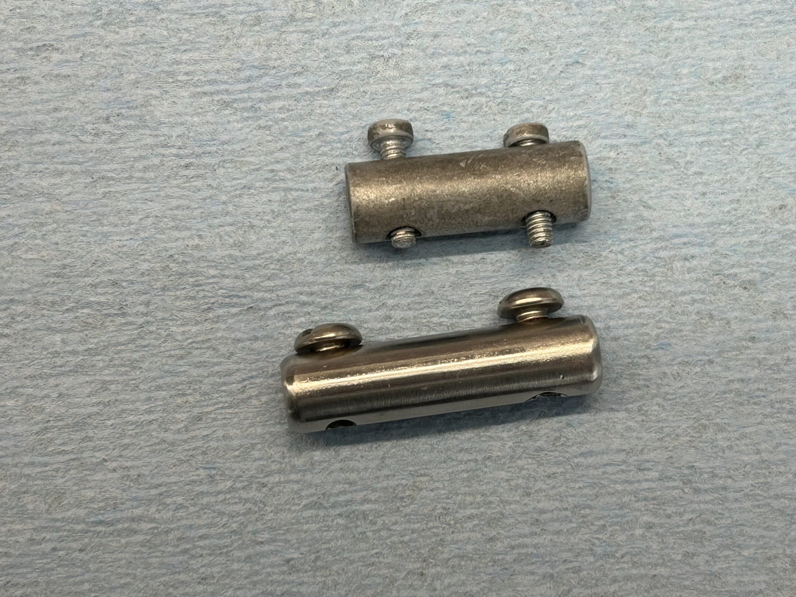
We then moved to the clutch slave cylinder and the installation of the remote bleeder kit purchased from Rivergate Restorations. We did need to add an extra “spacer” fitting (circled in red below) at the master cylinder so that braided hose would clear the edge of the “Sebring” foot box.

Modified Clutch Fitting Assembly

The slave cylinder mounted easy enough but the upper bolt is a real pain to get to once the gearbox is in the car. We used cap screws to make the job a bit easier. A cut-off (shortened) Allen key does the trick.

We fabricated a little bracket to hold the remote bleeder and used the two LH heater box mounting screws to hold it in place. In doing so, we avoided having to make any extra holes in the chassis.

Clutch Remote Bleeder Mounting Bracket

I installed a stainless bleeder valve in the fitting that Rivergate supplied. That was wrong and it leaked! We went back to the two-piece bleeder that Rivergate had supplied and everything was fine. We were able to successfully bleed the clutch system and we had no leaks. Again, this is detailed in the accompanying video.

Correct Bleeder Assembly for Remote Clutch Bleeder

We then mounted the radiator and the 10″ electric fan to the car. This also involved completing the wiring to the fan from the toggle switch below the dashboard. Instructions for wiring and mounting the fan are provided by Moss Motors. Contrary to what we typically see, the black wire from the fan is for power and the blue wire is for ground. Hayden Fan Instructions

The radiator mounts with four 1/4″ hex bolts. It is definitely easier to mount he RH side of the radiator first as seen in the video.

Radiator and Electric Fan Installation

It was then time to mount the gasket and the intake manifold and header to the cylinder head. We also added a new polished stainless steel carb heat shield. The order or sequence of the gaskets between the intake, the heat shield, the phenolic spacer block, the carb and the air cleaner is important. The K&N air filter will be added later after initial tuning of the engine. Lastly, the HIF44 carb was added.

Intake Manifold, Header and HIF44 Installed

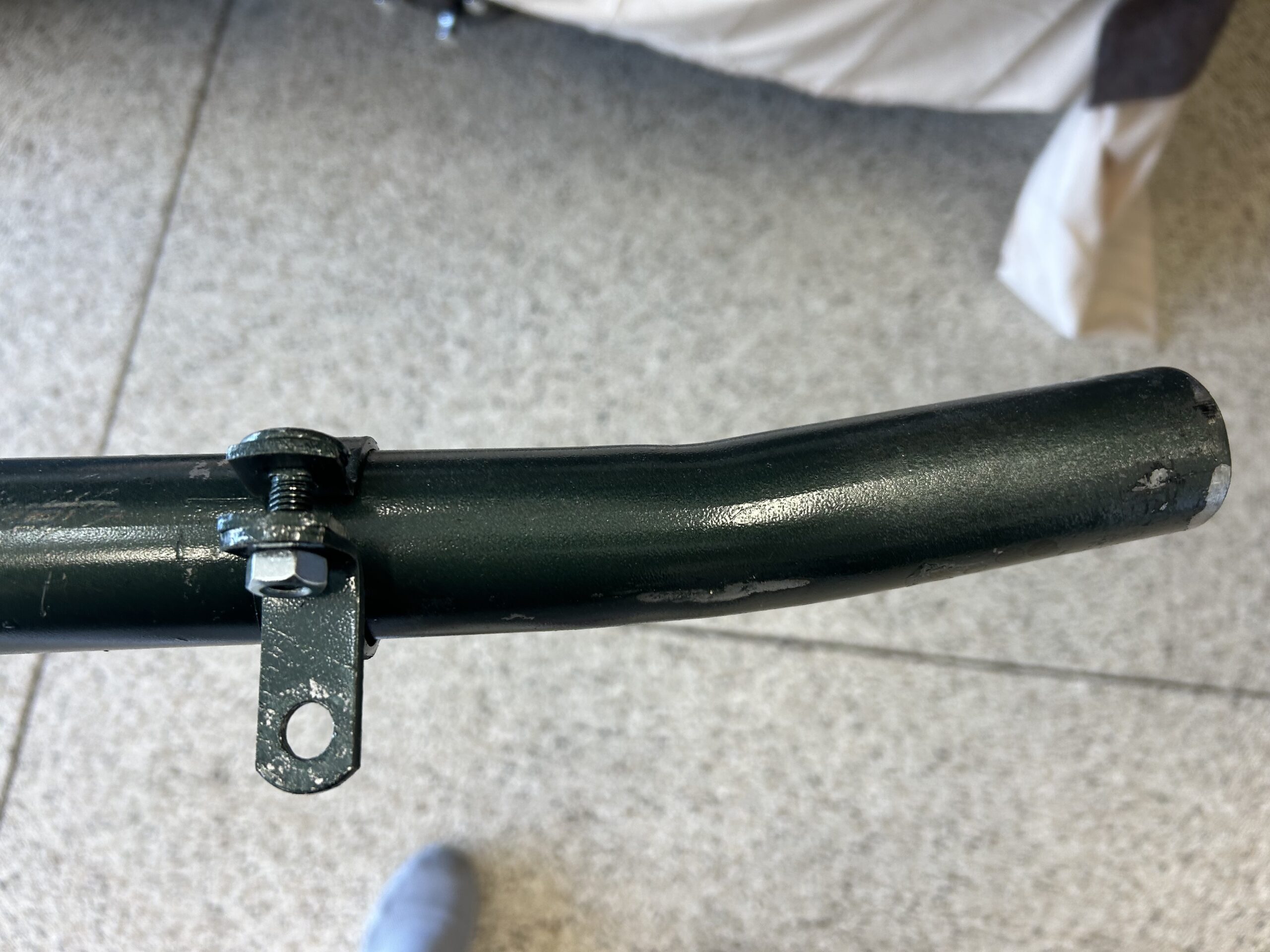
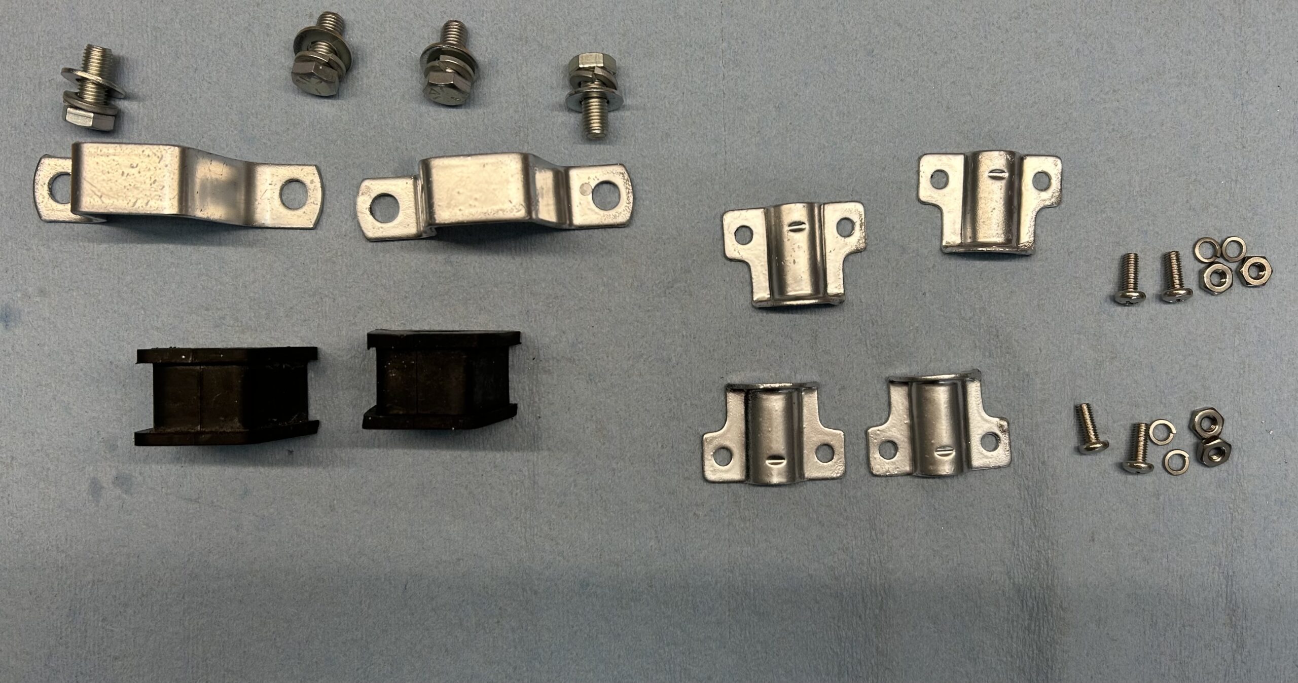
We made some stainless steel brackets sourced from McMaster-Carr and added a nut-sert fitting in each to hold the stainless clamps used to support the heater pipe. The original intake manifold had cast fitting for the heater pipe mounting but hose were forfeited with the new Maniflow intake.

Heater Pipe Installed

We then connected the fuel delivery hose, the carb float bowl overflow hose, the breather hose from the timing cover canister, and the vacuum hose from the carb to the distributor.

Hose connections to the HIF44 Carb

HIF 44 Carburetor (RH Side)

We added a little heat protection to the fuel delivery hose with a heat shield wrap from Techflex Thermoshield https://www.cabletiesandmore.com/thermashield-t6-wrap and secured it with four stainless steel zip ties.

Thermotec Hose Covering and Stainless Zip-ties

The coolant recovery bottle we had selected did not have an overflow port. We added one by drilling a hole in the top side of the tank with an “R” drill bit. We then tapped the hole with a 1/8″-27 NPT tap and thread in a straight brass fitting and painted it black. We used some clear silicone (opaque) tubing from the radiator to the tank so that we could visually inspect coolant flow and we used some black silicone hose for the overflow.

Coolant Bottle Hoses

Next, it was time to put fluids into the Bugeye!

Fluids into the Bugeye

We then installed the wiring for the AFR gauge from the interior to the oxygen sensor. We will only be using the AFR gauge for tuning and therefore it does not require a permanent wiring routing nor a placement of the gauge on or below the the dash.

Details on the forgoing are shown in this video: Bugeye Restoration Video Episode One Hundred-Three.

https://vimeo.com/1088106527/9f6138ea7f?share=copy

The following content is included:

0:00 – Engine ground strap to chassis

1:44 – Starter cable 

2:12 – Oil pressure gauge pipe

2:31 – Distributor and coil wiring

2:46 – Water temperature capillary tube

3:27 – Alternator, wiring connections

4:26 – Heater hose from water valve to heater box

4:44 – Clutch slave cylinder, remote bleeder

5:53 – Clutch bleeding

6:07 – Clutch slave cylinder

7:00 – Radiator

7:50 – Radiator hoses

7:53 – Electrical radiator fan installation

8:40 – Radiator fan wiring

9:50 – Intake manifold and header with gasket

11:05 – HIF44 carburetor

12:25 – Stainless steel carburetor heat shield

12:40 – Copper heater pipe and hose

13:25 – Breather hose from timing chain cover canister to carb

13:50 – Fuel delivery hose and float bowl overflow hose

15:30 – Techflex fuel hose insulation

16:23 – Vacuum hose from carburetor to distributor

16:40 -Coolant recovery tank relief port installation

18:45 – Fluids into the car for the radiator, engine, differential, and gearbox

20:38 – Temporary wiring for the AFR gauge


New Rubber for the Panasports

We decided on a vintage look in tires for the Bugeye. We ordered the tires from Longstone Tyres in the UK. https://www.longstonetyres.co.uk/155r13-pirelli-cinturato-ca67.html  They are 155 Pirelli Cinturato CA67 tires and have an aggressive-looking tread pattern. It took less than a week to have the tires shipped to us.

Pirelli Cinturato

We are mounting the tires on the 5.5″ Panasport wheels that were on the car previously. We didn’t want to take the tires and wheels to an “everyday” tire store for mounting and we were able to find a local custom shop to do the job for us. All Road Automotive in Sarasota was very accommodating and had the job done the same day we took the tires and wheels to them.

Rear Disc Brakes!

One could say that the rear brakes on the bugeye have been a journey. We began with the original drum brakes that were on the 948 bugeye, and then upgraded to later MG Midget rear drum brakes with the dual piston brake cylinders. That upgrade involved, new back plates, new cylinders, new adjusters, in new springs. If you read our earlier post regarding the upgrade to the later drum brakes, you know that it wasn’t an easy job as we ended up, having to modify the back plate and the drums to avoid rubbing.

Late in the game, after expense and considerable effort, we made the decision to upgrade yet again to rear disc brakes. In researching the topic, we discovered there were several vendors selling conversion kits. Frontline in England, https://shop.frontline-cars.co.uk/parts-and-upgrades/product/17 the Bugeyeguy in Connecticut, https://bugeyeguyparts.com/products/rear-disc-brake-kit and Ol Phartz Parts in California, https://www.olphartz.com/rear-disc-brake-conversion-kits.html

After some head scratching and deliberation we decided on the kit from Steve Christensen at Ol Fartz Parts. Steve’s kit is nicely put together and uses modern brake calipers sourced from a Nissan Sentra. Considerable documentation with photographs is supplied in the kit and was very helpful in assembly.

Bugeye Restoration Video Episode Ninety-nine shows the contents of the kit and our installation.

https://vimeo.com/1087193582/c834792afd?ts=0&share=copy

0:00 – Disc brake kit selection

1:20 – Ol Phartz’s parts kit contents

6:20 –  Painting components

7:18 – Removal of brake drums, hubs and backplates

12:05 – Caliper brackets installed

12:50 – Reinstall hubs, bearings, tab washers and axle nuts

14:18 – New axle gasket, “O” rings, and half shafts installed

14:30 – Brake rotors installed

14:57 – Caliper torque bracket installed

15:55 – Disk pads installed

16:05 – Spring clips and pad retainers installed

17:40 – Caliper body installed

18:40 – Brake hoses and axle brackets installed

20:15 – Handbrake rods and linkage installed

20:58 – Brake hard pipes installed to 3-way connector


Brake Pipes, Brake Flares and Initial Brake Bleeding

This topic was covered in two previous posts:

https://valvechatter.com/?p=14379 and https://valvechatter.com/?p=13973

The time came to bleed the brake system. Bleeding brakes for the first time always seems to be a stressful situation and in our case it was no different. With the Bugeye we are using DOT 5, or silicone, brake fluid. Using silicone fluid can be somewhat controversial, but the real benefit is that it does not damage paint. This was a particular concern with the Bugeye because if the master cylinders or their fittings leak, there’s no way to avoid brake fluid in the pedal box at a minimum.

Bleeding the system began with “bench” bleeding the brake master cylinder. This is done to get any air out of the master cylinder itself before filling all the pipes with fluid. It’s really quite easy to do this and the process is shown in the Bugeye Restoration Video Episode Ninety-seven.

Bleeding the Master Cylinder

Following our successful bleeding of the master cylinder we then used a Gunson Eezibleed kit to fill the system with fluid and begin purging the air from the lines. https://www.gunson.co.uk/product/G4062/Eezibleed-Kit. The kit uses a pressurized fluid bottle connected to the master cylinder. Air pressure is used to move fluid through the system. Air pressure comes from using a tire with pressure reduced to no more than 20 pounds.

Before putting any fluid in the Eezibleed container, we connected the supplied cap for Girling master cylinders and pressurized the system to see if we could hear any air leaks. Hearing none, we filled the container with fluid and pressurize the system.

Unfortunately, we experienced several leaks throughout the car. Most could be remedied by simply tightening the fittings, a little bit more than we had previously. However, in the case of the pipe that is routed from the brake union on the right hand engine bay valance to the rear of the car, we concluded that we had improper pipe flares causing leaks and decided to remake the pipe.

Because we were eager to get the job done, we ordered 3/16″ nickel/copper brake pipe from Amazon. This turned out to be a mistake. The walls of the pipe were thinner than the pipe we had previously ordered from Fedhill. Fedhill is the go-to source for brake pipe and fittings used on vintage British cars. The thinner walls on the Amazon pipe prevented making quality flares. So, we ordered a 25′ roll of pip from Fedhill and waited for delivery by the USPS. For the pipe running from the union to the rear of the car, the flare at the union should be a bubble flare. The flare at the other end of the pipe which connects to the Goodridge flex hose at the axle, requires a double flare. In fact, each of the pipe flares (3) joining with a flex hose require the double flare. All other flares are bubble flares.  Making the pipe flares and installing the new pipe in the car is shown in the Episode Ninety-seven Video.

https://vimeo.com/1087163945/947d5a54b9?ts=0&share=copy

0:00 – Bench bleeding the brake master cylinder

2:10 – Brake pipe purchase information

4:13 – Brake pipe flares: bubble and double flares

We have decided to change gears and install disc brakes on the rear of the car so we will pick up with the completion of the bleeding of the brake system following the installation of the new rear brakes.

Exhausting

Twenty years ago we installed a Maniflow exhaust system on the Bugeye. It was purchased from MiniMania. We were always happy with the sound of the car so we opted for another Maniflow system with this new version of the Bugeye. The header was the same one we had used previously we simply updated the finish opting for the Jet-Hot ceramic coating. 

The exhaust pipes, mounting hardware and the muffler were sourced directly from Maniflow in the U.K. https://www.maniflow.co.uk/index.php?view=product&from=207&product=1260. The parts come from Maniflow painted in their signature dark metallic green paint. We opted to paint over the green with a high temperature Rustoleum satin black spray paint. 

We were hoping to be able to use one of the left rear bumper mounting bolts for the rear mount of the muffler but we weren’t happy with the fit. In fact, we weren’t happy with the rear muffler at all. Perhaps on the MG midget or square body Sprite, the muffler is fine but on the Bugeye the muffler seems to hang to low and is very obvious from the rear of the car. Consequently, we decided to reuse the Maniflow silencer we already had. We cleaned it up, painted it and mounted it to the car. We did end up drilling an extra hole in the trunk floor for the rubber mounting bobbin to secure the silencer. 

The video below shows the installation of the exhaust system in the car.

Bugeye Restoration Video Episode One Hundred-Four: https://vimeo.com/1082272507/6be54040aa?share=copy


Engine/Gearbox Installation

John and Molly came over to assist in the “Big Lift,” the installation of the engine and gearbox into the car. This has been a long time coming. As a reminder, we are installing the 1275 engine along with a Datsun 210 5-speed gearbox. The following image shows the same procedure twenty years go!

Engine Install 2005

Unfortunately, many have reported that the heater plenum needs to be “bashed” upward to provide clearance for the entry of the gearbox. We had hoped that we could avoid this step if we were very careful and took our time, but it was not to be. In the end we had to “adjust” the plenum to make room. That process is shown in the accompanying video. 

We put together a check list of items that combines preparation steps along with necessary connections to get the engine in and then make it ready to start.

Remove Bonnet – struts and hinges.take the strut off first. before removing the bonnet hinges disconnect the Deutsch connector and the spade connector at the horn.

Jack Stands – place the car on jack stands.

Engine Hoist Leveler – Remove rocker cover and install leveler on engine.

Engine Mounts – Move rubber buffer from engine stand to the car mount.

Starter – Attach the power cable to the starter that will connect to the starter switch later in the process.

Battery Ground cable to firewall – disconnect during engine install.

Engine fan –  install six blade fan and spacer. Install fan belt and check tension.

Crossbar protector – put the custom-made sheet metal protector over the steering rack crossbar to avoid damaging the paint.

Remove fluids –  from engine, radiator and transmission

Timing marks – make sure these are visible on the pulley before installing the engine.

Driveshaft Prop – Grease the yoke and the transmission splines.

Slave cylinder – check threads of the two mounting bolts, should be metric. The threads of the push rod extend beyond the arm by approximately one half inch (6-8 threads showing). The excess on the spacing shim goes to the front of the engine. Find the slightly shortened Allen key for the new cap screws.

Engine Mounts – Install the left-hand engine mount onto the chassis and leave it loose. Install the right hand engine mount onto the engine and leave it loose.

Header – Set the exhaust header in place so that it will be positioned to install once the engine is in place.

Engine/transmission install with engine hoist – Check to see if the heater plenum will require modification. Before the assembly is all the way home push the driveshaft yoke into the rear of the transmission.

Transmission mount – install the ⅜” – 24 x 3 ½” bolts through the chassis and into the mount and tighten. Next, tighten the front engine mounts. Now center the transmission in the rear mount and tighten the transmission pad mounts. Install the bolts in the sides of the rear mounts from the inside of the car with the self locking nuts inside the tunnel. It may be helpful to tape the nuts in the wrench to make starting the threads easier.

RadiatorIt is a little tricky to install. It works best to begin with the upper right (passenger side of the car) mounting point first, then the lower right, followed by the upper left mount and finally the lower left mount. 

Radiator hoses – connect and clamp

Overflow coolant tank – determine right place for the overflow tank drain line and install a fitting in hose. Connect the radiator overflow to the tank.

Alternator – connect the wiring for the alternator.

Vacuum Pipe – connect the vacuum hose from the distributor to the carburetor.

Starter – attach the power cable from the starter to the starter switch.

Ignition Coil – attach the wiring to the coil and distributor. Connect the high tension line from the distributor.

Oil pressure gauge pipe/hose – connect to engine.

Water temperature gauge – connect capillary tube two cylinder head.

Rocker Cover – install the rocker cover.

Breather hose – connect the hoses and clamp

Driveshaft – connect and tighten bolts/nuts.

Refill fluids in engine, radiator and transmission – transmission requires 2 ¼ pints of Redline MT-90.

Clutch – Bleed the clutch master and then the slave cylinder. To eliminate all air, the slave cylinder piston should be held in the fully retracted position while bleeding. Do this by running out the adjustable push rod until it is pushing firmly on the clutch fork. Keep the master cylinder reservoir topped up while slowly and gently pumping the clutch size cylinder Into operating position. A power bleeder works well here.

Adjust the push rod length to give some free travel at the clutch pedal. Assure clutch is releasing fully while the vehicle is still up on jack stands. Confirm free play assuring that you can move the clutch operating lever away from the clutch slave cylinder push rod. Finger pressure against the lever should be able to move it against the pressure of the spring inside the Bell housing. Generally 1/4 inch to 1/2 inch of free play measured at the fork will be adequate. Be aware that the clutch pressure plate can be over traveled. If the clutch releases when the pedal is partway down, but then seems to reengage at full pedal down. It is being over traveled. Add free play until this condition disappears.

https://youtu.be/k11eIyfErMY?si=YUO94N5qavN61VFl

Battery ground cable to firewall – reattach.

Ground Strap – Attach engine to frame

Intake and Exhaust Manifolds with gasket – brass long nuts

Carburetor –  install heat shield, phenolic spacer, choke and accelerator cable. Connect fuel hose from pipe to carb. Connect vacuum hose to distributor. Put ATF in the carb piston. Connect carb drain hose.

K&N Air Cleaner – Install and spray with special oil.

Heater hoses – attach both and clamp

Exhaust system – install, exhaust header, exhaust pipes, and muffler.

AFR gauge – connect gauge to the O2 sensor and power.

Gasoline – partially fill fuel tank with gasoline.

Battery – reconnect the battery ground cable to the firewall.

Start engine!


These things always take longer than expected, or at least hoped! However, at the end of the day, all that is important is that you got the “thing” in. Well, it was about the end of the day and we did get it in!

We did install the new slave cylinder sourced from Will Perry at Rivergate before the engine went into the car. Once the engine is installed there is not much room between the gearbox and the frame making it a tight squeeze to install the slave cylinder. We are also using a remote bleeder with a flexible hose.

Slave cylinder install

Bugeye Restoration Video Episode One Hundred-Two shows the process involved in the installation of the engine and gearbox as well as the short-throw gear shifter sourced from Gerard Chateauvieux at Gerard’s Garage.

https://vimeo.com/1076516667/7bc5103b4c?share=copy

Additional information about Gerard’s shifter is provided in another post: https://valvechatter.com/?p=13520

Bugeye Restoration Video Episode One Hundred-Three shows the process involved in making the various connections required to prepare the engine to start and the gearbox to operate properly. This video will be posted when complete. 

Windscreen Installation

We purchased the laminated windscreen and rubber glazing from AH Spares. It is made by Pilkington and is their premier product. https://www.ahspares.co.uk/austin-healey/sprite/windscreen-glass/screen-glass-triplex-pilkington.aspx 

We decided to have the stanchions and the frame ceramic coated because the car is kept near the Florida coast and we wanted the extra protection. Cerakote was used and was applied by C2 Coatings in Sarasota. Often it is the case that the rubber seal between the windscreen and the body does not fit properly,. We purchased the one we used from Martin McGregor at McGregor’s Upholstery and it fit perfectly.

Many Bugeyes do not have their windscreen seal installed correctly. Often, the seal between the body and the windscreen is simply cut off at the windscreen post or stanchion. Proper installation involves modifying the seal to permit it to fold under the stanchion rubber seal. This will minimize leaks and certainly looks better.

Bugeye Restoration Video Episode One Hundred is a short video that illustrates the installation of the seal that fits between the body and the windscreen and then the installation of the assembly to the car. Our seal was sourced from MCGregor’s in Canada and is supposed to be an accurate representation of the original seal. 

https://vimeo.com/1075349533/bfe9ed4530?share=copy

Aston Fuel Filler Pipe Cap

We wanted to “upgrade” the fuel filler pipe cap in favor of an “Aston” cap sold by Sports and Classics https://www.sportsandclassics.com/parts/austin-healey/austin-healey-100-6/fuel-system-austin-healey-100-6/le-mans-aston-gas-cap-austin-healey-mgb-mgc-midget/

Aston Fuel Filler Pipe cap

It is a nice looking cap and from a practical standpoint its installation does eliminate the fear that one might drive away from the pump without installing the filler cap. The cap is polished cast aluminum. To make the installation work we purchased a used fuel filler pipe from an Austin-Healey 3000, cut the lower end off so that the modified pipe was 9 1/4″ long and epoxied the brass screw collar for the cap to the top of the pipe.

Filler Pipe Cap with Brass Collar

Fuel Filler pipe with brass collar

We were then painted our new pipe with POR 15 and fit it through the rubber body seal and into the rubber 2 1/4″ elbow hose to link it to the fuel tank. The elbow hose is used in later Sprites and MG Midgets and was available from Moss Motors. https://mossmotors.com/282-945-hose-filler-to-tank

Two hose clamps were then used to secure the hose to the pipes.

Aston Cap Installed

The components and the installation of the cap is detailed in Bugeye Restoration Video Episode Ninety-six: 

https://vimeo.com/1050923286/e891e27912?share=copy


Loose Ends

This post covers several items added to the car as we begin to near the completion of this restoration.

Rear Tie down brackets (tow hooks)

In an earlier post the front tie down brackets, or tow hooks, were mounted to the car. We also purchased rear tie down brackets or tow hooks from Q1 Classic Engineering. These are heavy duty and very nicely made. We painted them black with POR 15 and easily installed them.

Rear Tie Down Brackets

Battery management quick connect cables

We then added some wiring to the battery so that we would have a quick connect system for the battery management charger. This is particularly useful given that we have a cover on the battery.

Battery Management Quick Connect Wiring

Horns revisited

We discovered, with the installation of the bonnet gas struts, that the operation of the RH strut hit the interior horn. So, we decided to forgo the second horn and just use one. The single horn,  by the way, seemed plenty loud.

Dropping the Interior Horn

Painting the exhaust

We are not ready to install the exhaust but this was a good time to go ahead and paint it. It came from Maniflow with their familiar metallic green paint. We simply roughed it up with a little sand paper and sprayed it with Rustoleum black BBQ high temperature paint.

Maniflow Metallic Green

Exhaust painted high temperature semi-gloss black

Installing the anti-sway bar

We then installed the anti-sway bar that we purchased from BugeyeGuys.com. We had previously painted the components so this turned out to be a quick job.

Anti-sway bar bits

Installing the motor mounts

The motor mounts were then installed. However, when we are ready to install the motor we will remove the RH motor mount and fix it to the motor. The LH mount will remain in the car because it is easier to leave it due to the steering column.

Heater control cable

We then connected the heater flap control cable that comes through the firewall from the heater switch to the bracket on the heater blower. 

Machining a starter cable connector

For some reason the standard connector that joins the starter cable and the starter switch is too short to do the job on the car. We know that the battery tray was replaced and perhaps the starter switch mounting bracket that is attached to the tray was slightly off? At any rate we solved this problem by machining a new connector made from a 3/8″ stainless steel bolt. Our friend Randy Forbes did the mill work for us. Thank you Randy! The new piece – almost identical but about a 1/4″ longer worked beautifully.

A new stainless starter cable connector

The new and the old

Repainting the Sprite Flash

The flash emblem or badge as mounted on the rear deck of the car was gold with red lettering. Unfortunately, the replicas of the badge available from the usual suppliers is copper in color with the red lettering. So, we stripped the paint from the badge and then repainted the badge with Rustoleum metallic gold spray paint, followed by painting the red letters and finally coating the badge with Rustoleum Krystal Clear. We were pleased with the results. We are going to mount the badge later and will be using a 3M adhesive rather than mounting it through holes in the car.

The gold paint first

Followed by Red in the letters and Clear

Re-chroming the grille

The grille is an important feature of the design of the Bugeye as it is what defines the ever-popular “smile” of the car. Modern replicas apparently do not fit very well so we decided to re-chrome the original because we knew it fit. We sent it to Dallas Plating https://dallasplatingga.com  in Dallas, Georgia and we were very pleased with the quality of the work and the delivery time.  It took only 3 weeks from the time we put the grille in the mail until we unpacked it. The charge for the plating was $440 and that seemed very reasonable compared to other businesses we checked.

Re-chromed Grille

Re-chromed grille sitting in place


Bugeye Restoration Video Episode Ninety-five covers the installation of the items mentioned in this post:

https://vimeo.com/1046168116/36c5ceb74e?share=copy

0:00 – Rear tie down brackets – tow hooks

0:39 – Quick connect battery management cables

1:28 – Revisiting the horns

2:33 – Painting the exhaust

3:18 – Anti-sway bar installation

4:46 – Motor mounts installation

5:11 – Heater control cable attached

5:24 – Machining a new starter cable connector

6:40 – Heater and starter cable covers

6:54 – Repainting the rear deck “Flash” badge

7:30 – Re-chroming the grille


Bonnet Headlights and Flashers

Headlights

After some initial work on the installation of the hinge kit on the bonnet, we turned our attention to the headlights. The assembly of the headlight components, mounting the headlights to the bonnet, and the switch to LEDs from halogen bulbs has been previously addressed in two separate posts, so we won’t go into much detail on the process as we mount the headlights to the painted bonnet. See the headlight fitting post here: https://valvechatter.com/?p=14074

Information about the conversion to LED lights throughout the car may be found here: https://valvechatter.com/?p=14188

Front Flashers/Turn Indicators

Mounting the flasher units to the bonnet is pretty straightforward although installing the beehive glass and the chrome trim ring into the rubber boot can be a test of one’s patience, but that is what it takes – lots of patience. Before installing the light assembly we installed three spire nuts at each light mounting point. We used new nuts and they pushed on easily. Three stainless steel #6 Phillips sheet metal screws are used for each light.

Bugeye Restoration Video Episode Eighty-eight shows the installation of the headlights and flashers/turn indicators:

https://vimeo.com/1043298584/6820215ce0?share=copy