We have never been very happy with the brakes on the Bugeye. We installed front disc brakes but the pedal travel was way too much and the master cylinder always seemed to leak slightly. We were going to replace the master cylinder with the correct one for the 1098 car, but others suggested that the original 948 MC would work fine if everything else was working properly. Having the rear brakes adjusted properly and using aeroquip stainless steel brake lines were the primary suggestions for brake improvement.
We installed the stainless brake lines, and fitted new green stuff disc brake pads in the front, with new shims also. Purchased and installed new copper alloy brake lines throughout the car. Paul Asgeirsson was a big help on the proper process for adjusting the rear brakes.
Put the springs on the brake shoes from the back plate side BEFORE putting in the adjuster. Lots easier.
To put in the adjusters with the springs in place, just pry down the bottom shoe away from the wheel cylinder with a screwdriver.
Disconnect the parking brake cable from the cylinder brake arm.
Put the drum on over the shoes and put on the 2 drum holding screws. These originally are pozi-drive screws and the phillips head screwdriver just chews them up. Get some new ones that are phillips head. They are 1/4 X 28 X 3/4″ flat head machine screws. Readily available.
Now adjust the brakes up as tight as you can. Press on the brake pedal pretty hard to seat the shoes. Check the shoe adjustment by rotating the drum if you can. If you can tighten up the adjuster nice and snug and back off one click. Do both sides this way. Should be able to rotate the drum OK, but typically not freely.
Hook up the parking brake clevis. If it’s too short, loosen the adjuster inside the car. 5/8″ deep socket and hold the cable with a 1/4″ wrench on the flat spot. Loosen until you can hook up the clevis. Do both sides this way.
Now you need to final adjust the parking brake. Take up the slack on both cables until they are just beginning to affect the rear brakes. Make both cables equal tension. Easy to check when you pull on the handle like you are parking the car.
Now the parking brake handle should only go up about 15 to 20 degrees. Now this is important. Never change the adjustment inside the car again until you reline the rear brakes again.
As the brakes wear, the handle will come up to maybe 45 degrees or so. That’s a signal to readjust the rear brakes. When you do that, the park brake handle will only pull up 15 or 20 degrees again.
Paul also provided some brake adjusters for the rear drums that were in good shape and we used those. New brake shoes were also installed. Speed bleeders were used on the front calipers and the rear wheel cylinders. While working on the rear axle it seemed that the time was right to add new seals and gaskets.
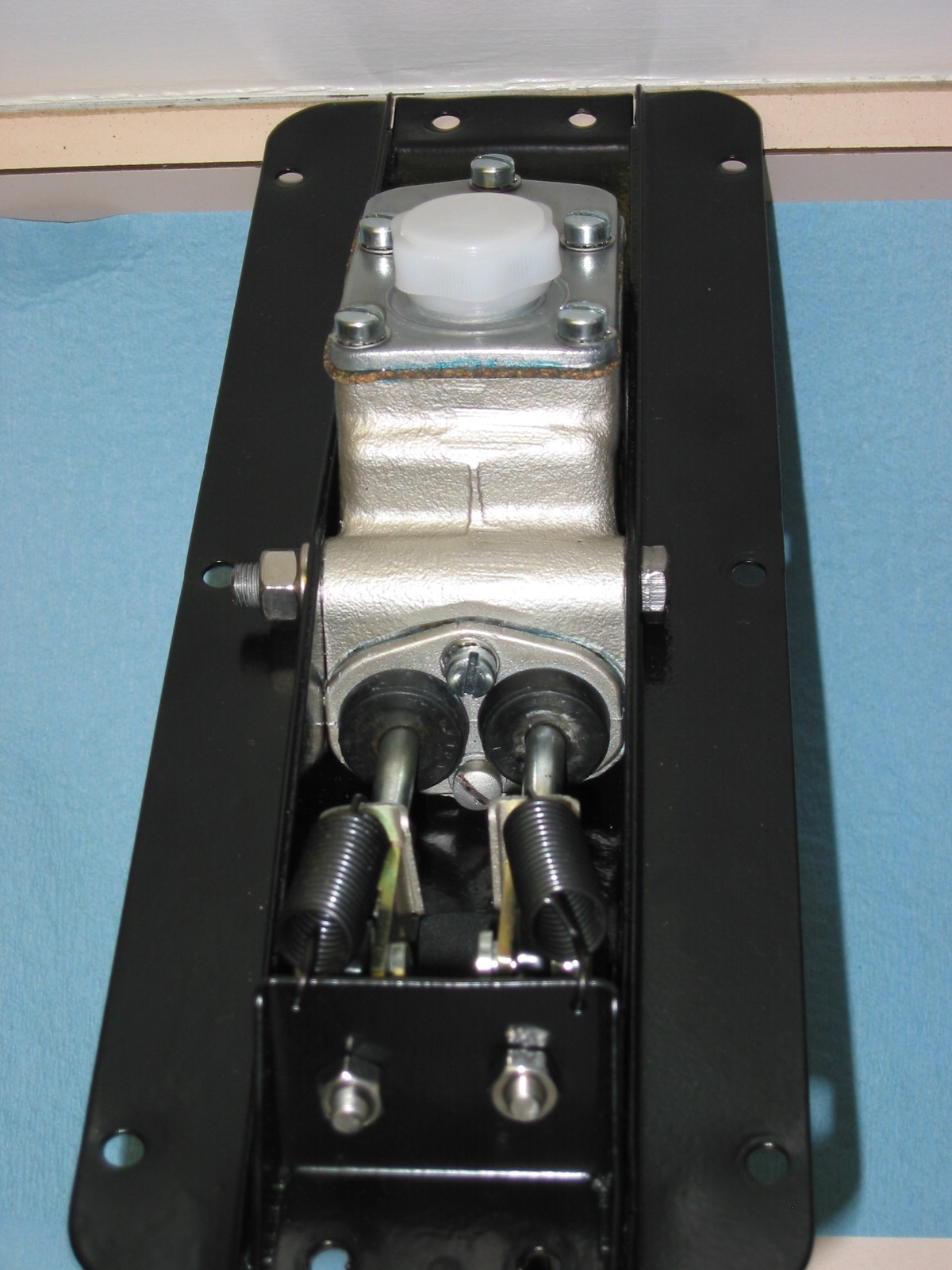
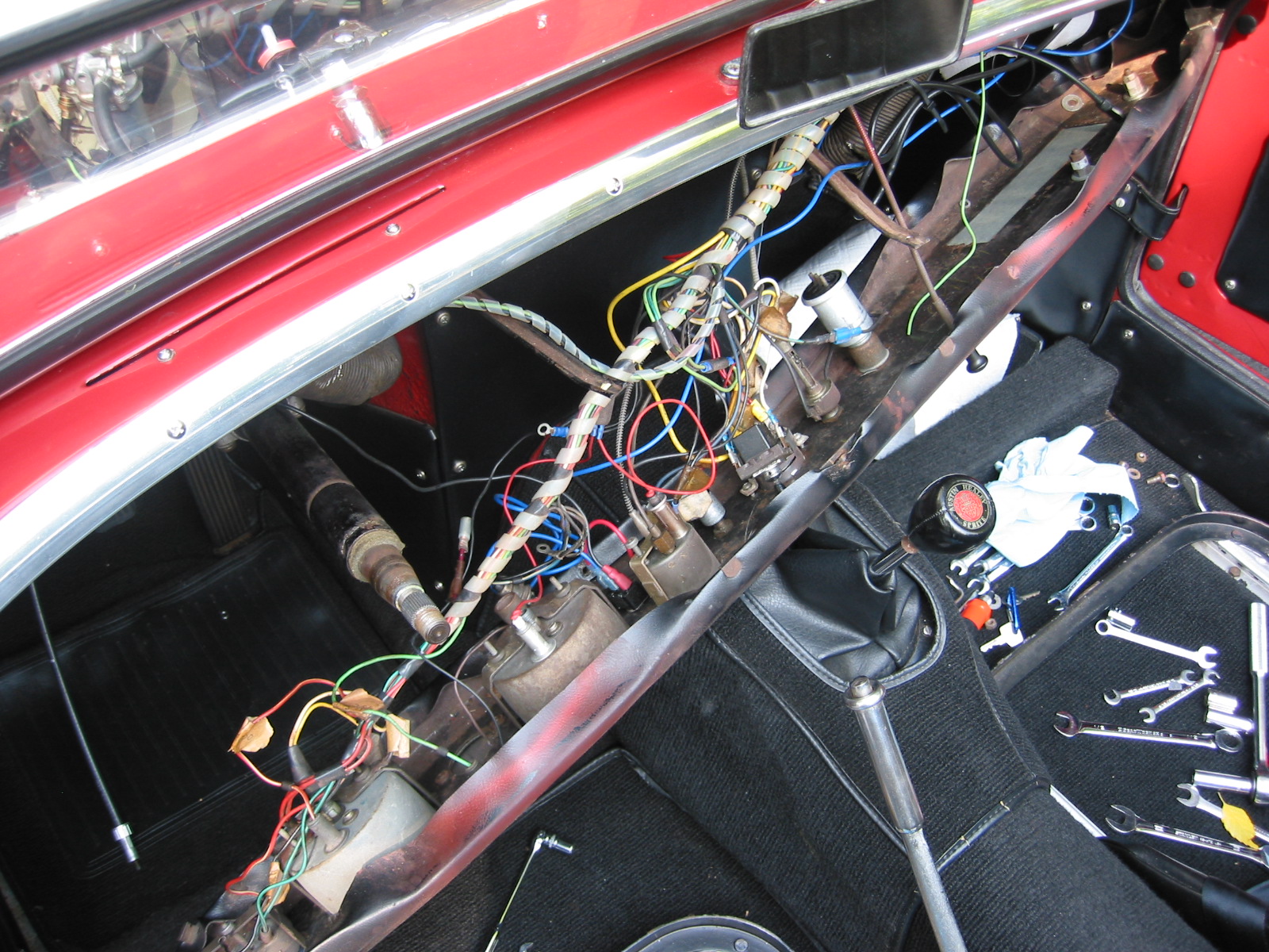
The old pedal box was a mess from leaky brake fluid so the box was pulled, cleaned up and powder coated for a more permanent finish. New gaskets were added to the master cylinder along with new push rods, clevis pins and etc. Also added new aluminum racing pedals to the brake and clutch pedals.
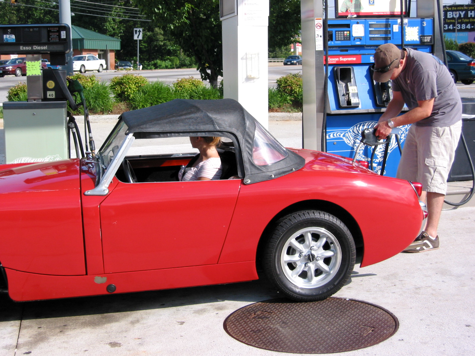
Finally, the system was bled and all the hard work was worthwhile!! Improved brake pedal and now we eagerly await actually putting the car on the road.

Powder Coated Drums
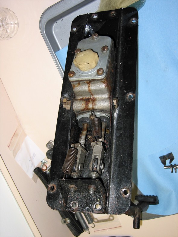
Ugly Pedal Box
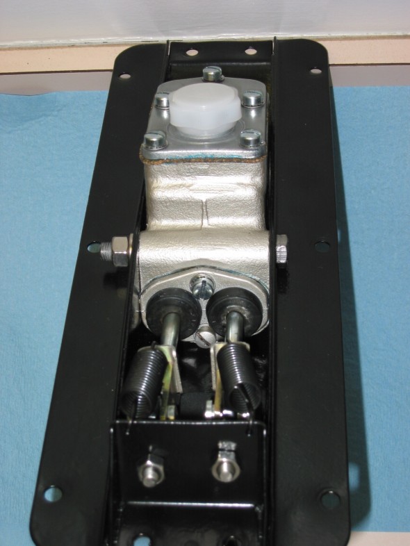
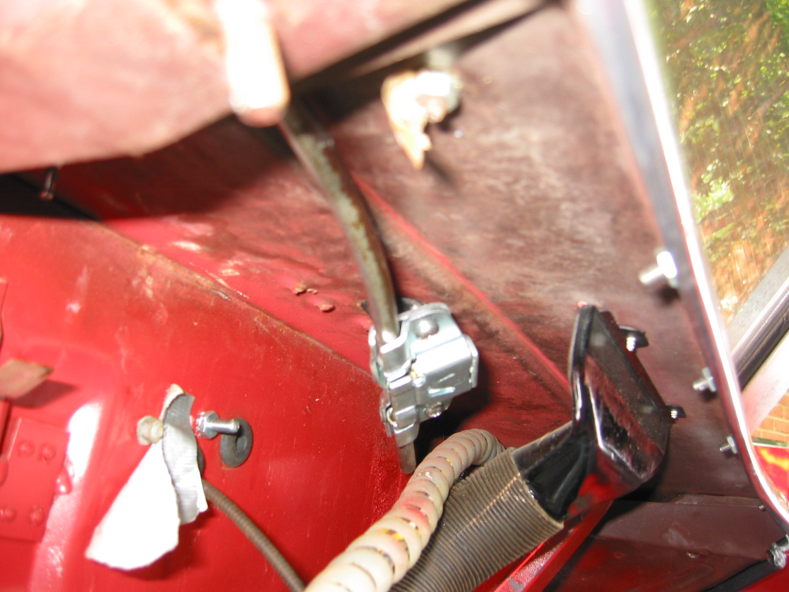
Powder Coated Box

Pedal Box Restored