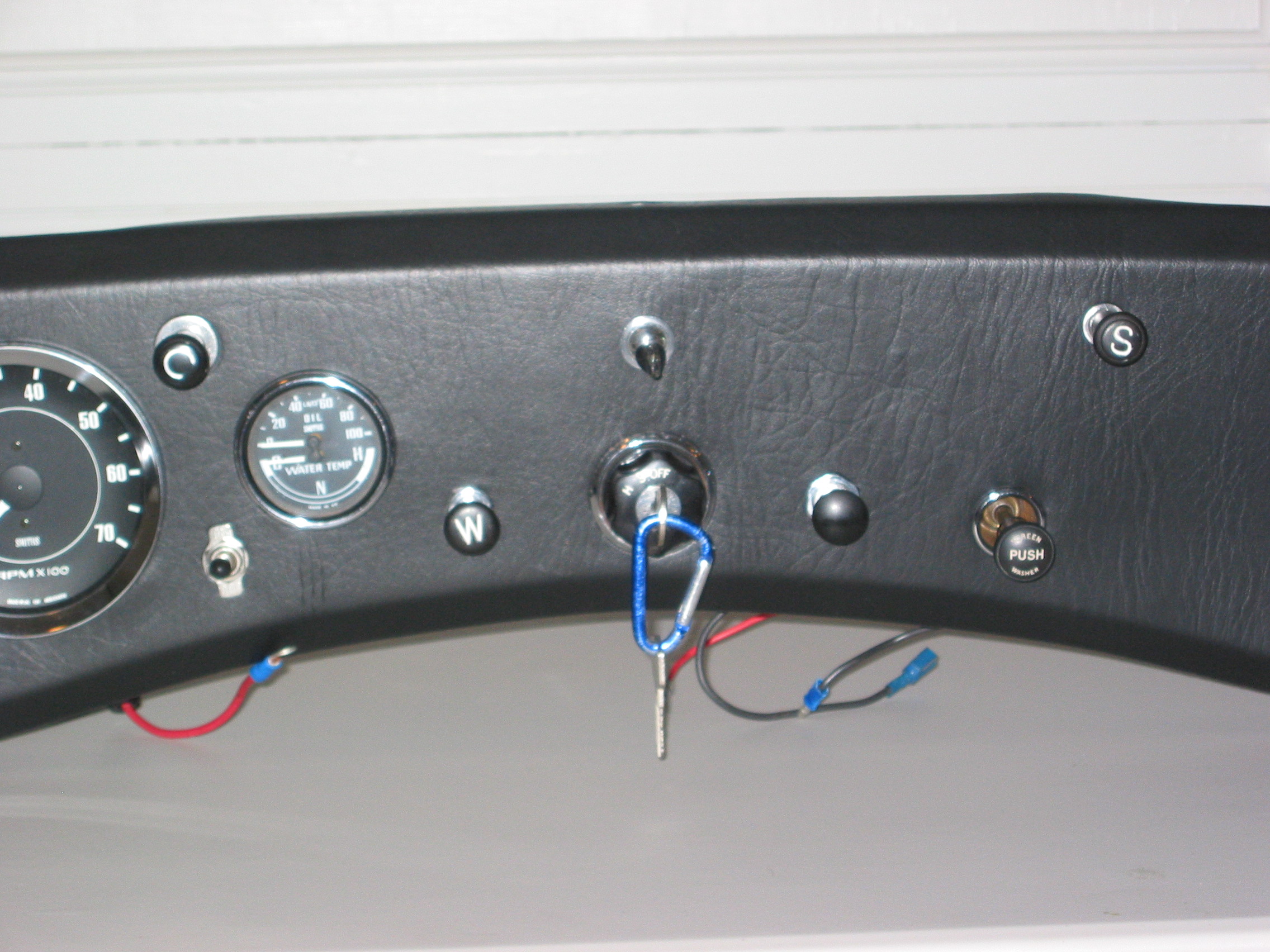
When we bought the Bugeye, it came with a working tachometer and a dead speedometer. After thinking about having the original instruments refurbished or buying new ones I decided to buy new Smith’s gauges. Keeping the original tach would have involved installing the guts of an electric tach into the casing of the old gauge since we had previously installed an alternator making the original worthless since it had a mechanical drive off the back of the dynamo.
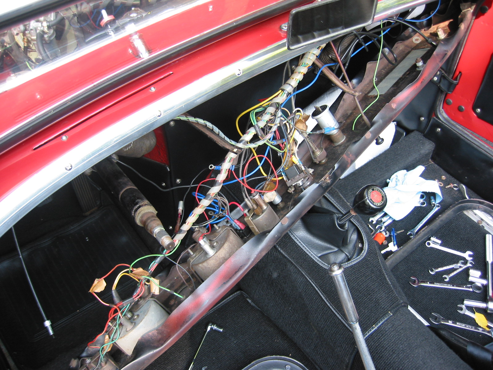
So the new gauges were ordered from APT Instruments, but it would be terrible to install them in the old dash so replacing old vinyl with new naugahyde was the only thing to do! I began the removal of the dash and proceeded slowly, carefully labeling the wiring to each instrument or switch.
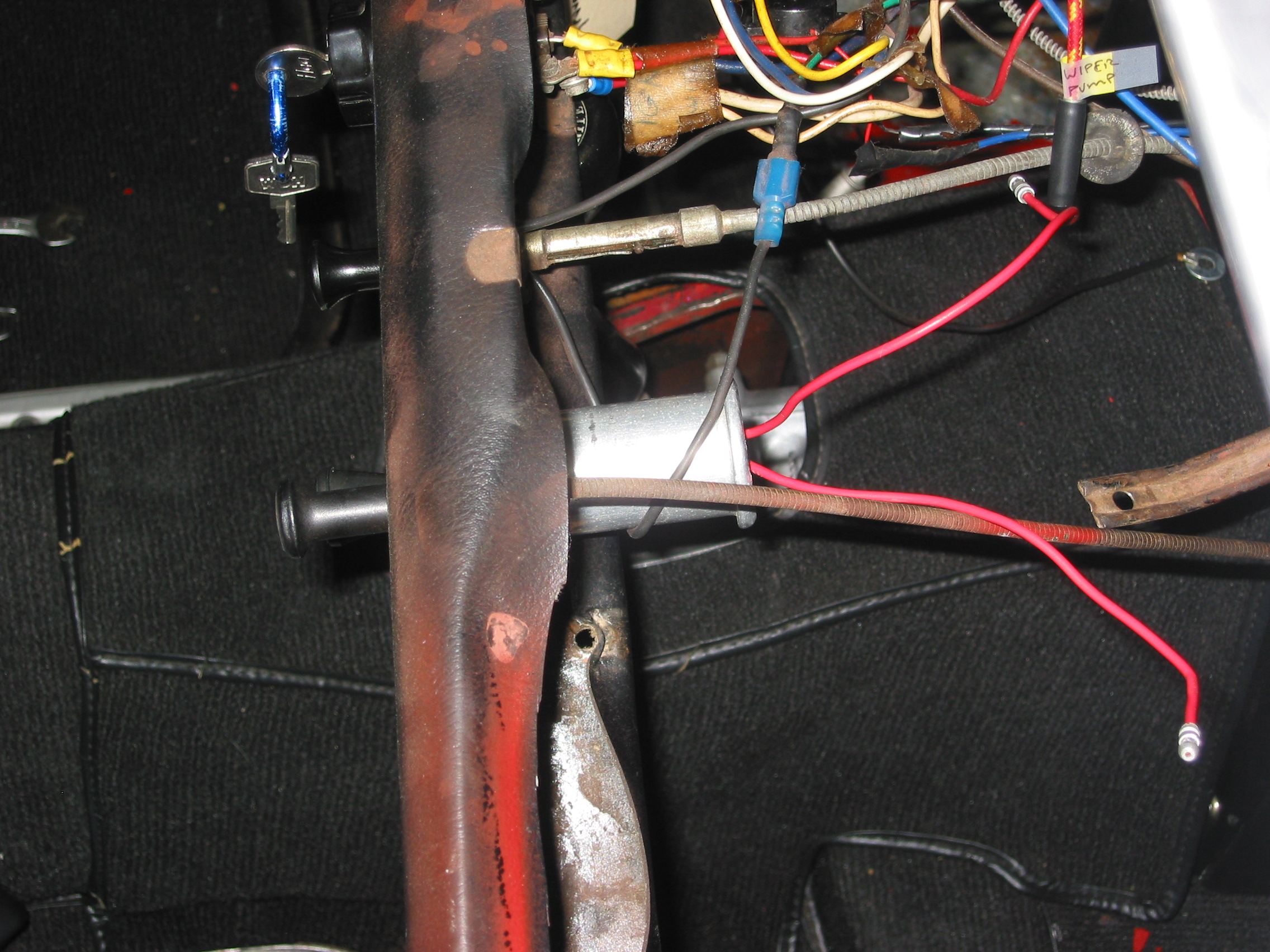
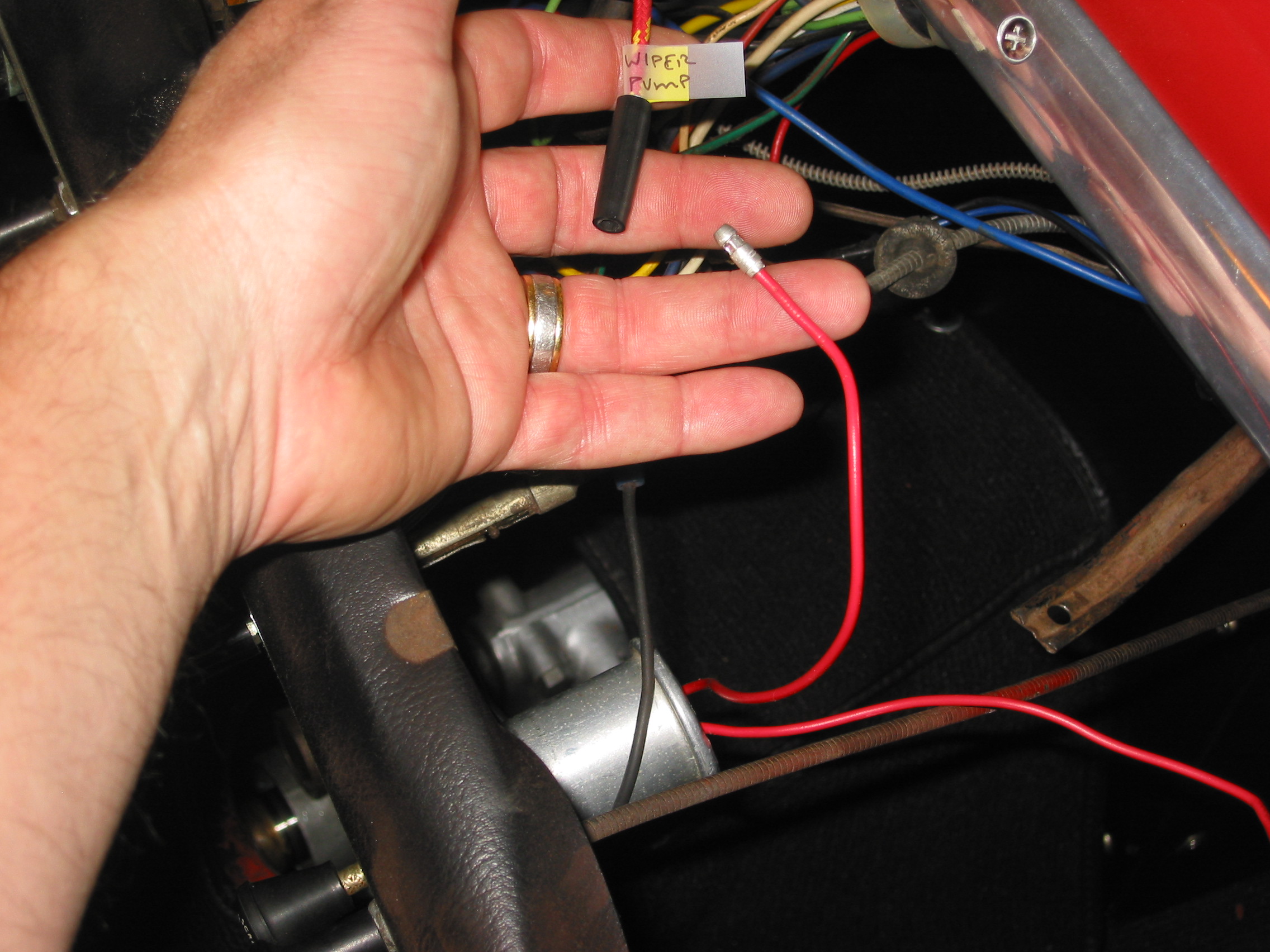
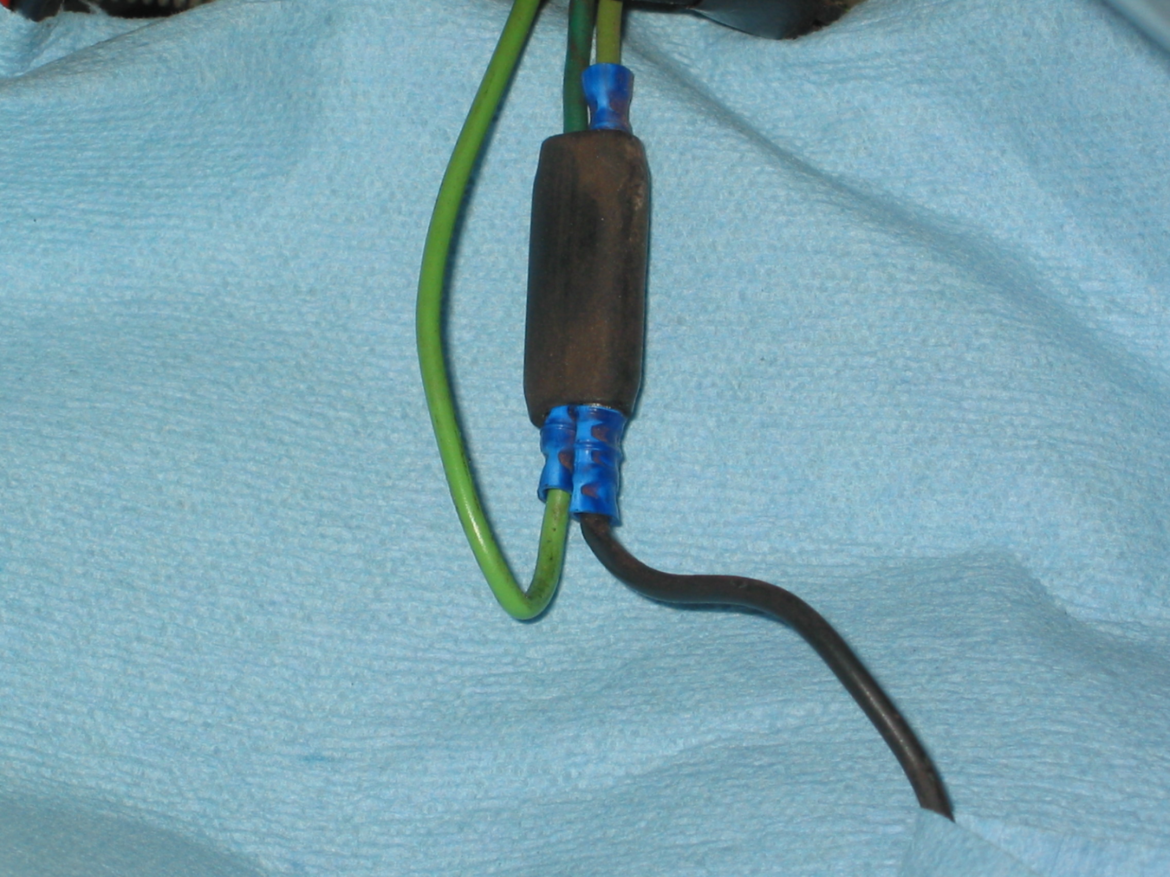
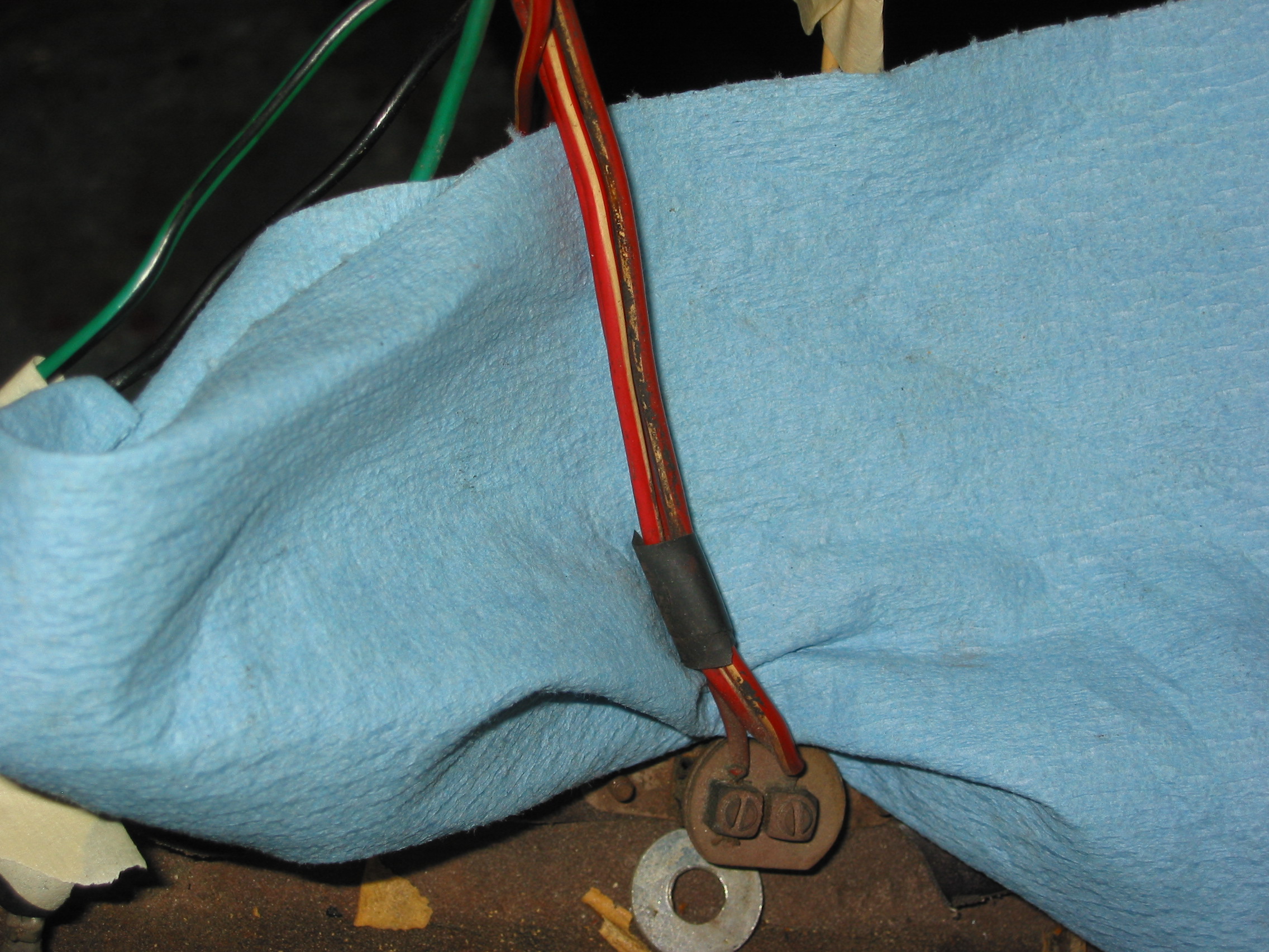
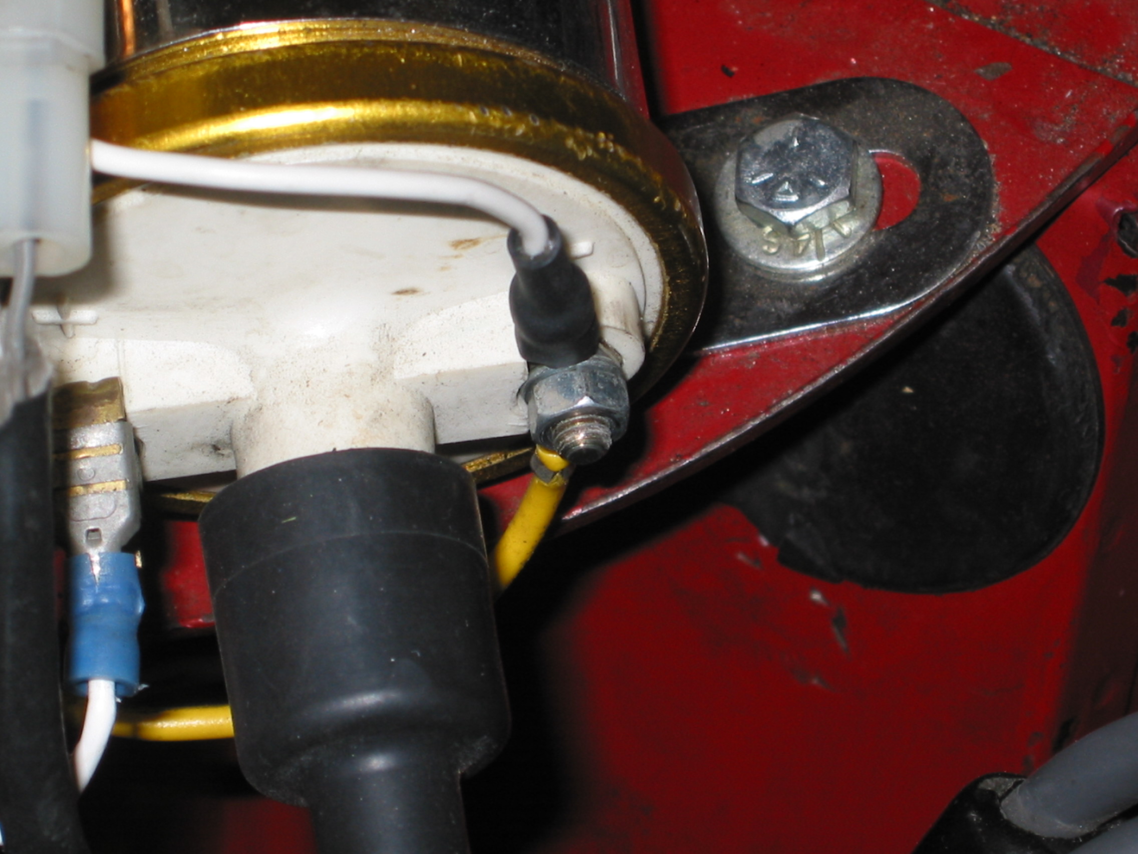
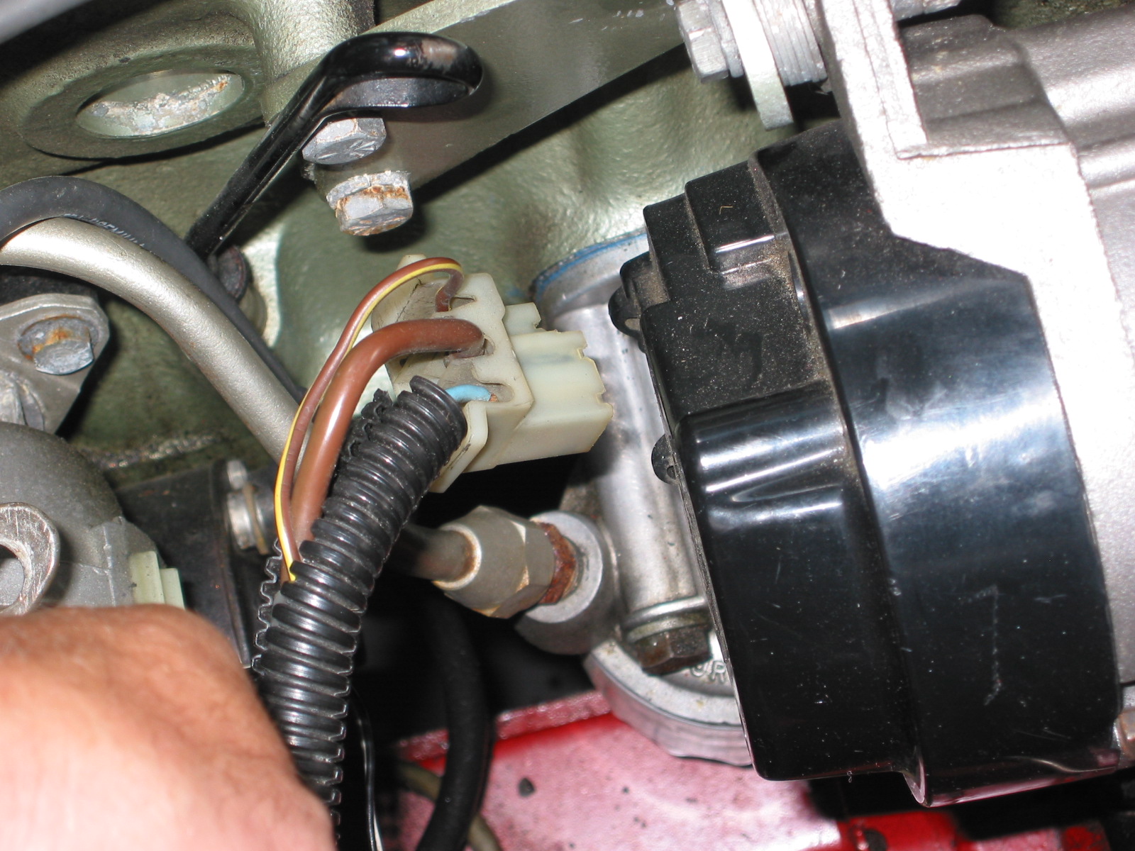
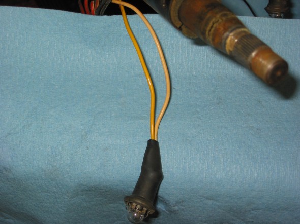
I initially disconnected 2 orange/yellow braided wires to the wiper washer pump. Using a micro switch, my dad had previously converted the manual pump for the windscreen washer to an electric pump. Next was the heater switch. I disconnected a green/brown wire from the harness from a black wire to the heater switch. Then I disconnected a black wire from the heater switch body from a double bullet connector into a light green wire.

Washer Wiring

Washer Wiring
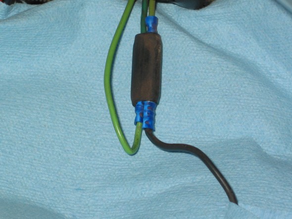
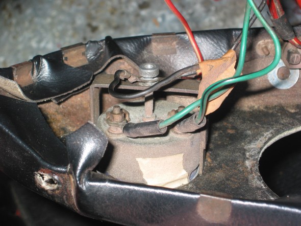
Heater Wiring

Heater Switch Wiring
The turn signal wiring was next. The switch has three spade connectors. On the side with tow spades, a yellow wire attached to one and a blue wire to the other. A white wire was disconnected from the side of the switch with the single spade.
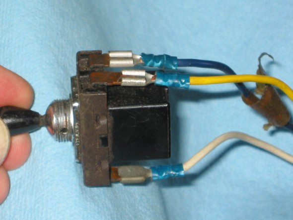
turn signal switch
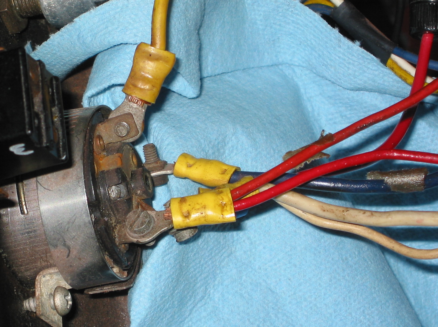
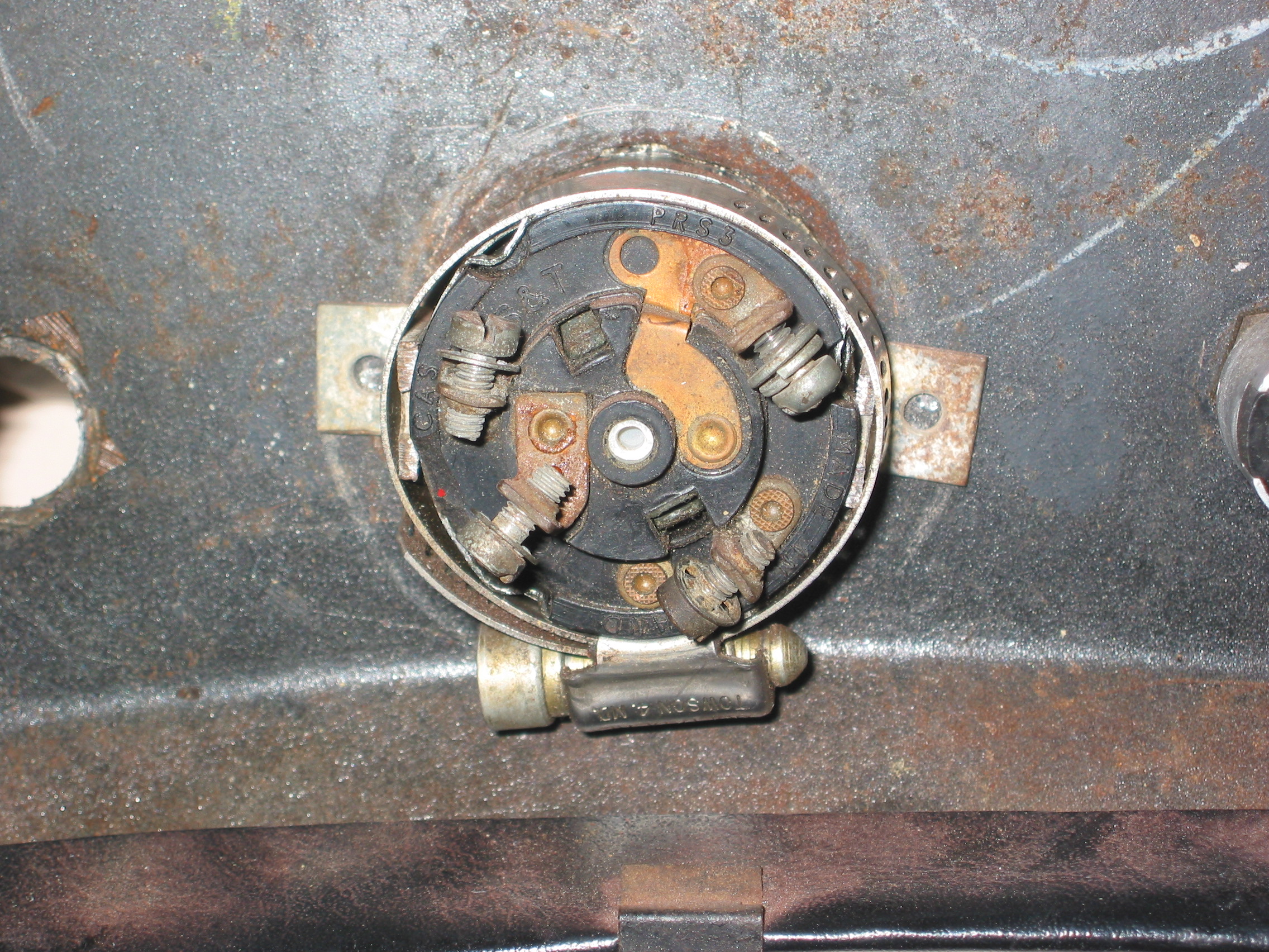
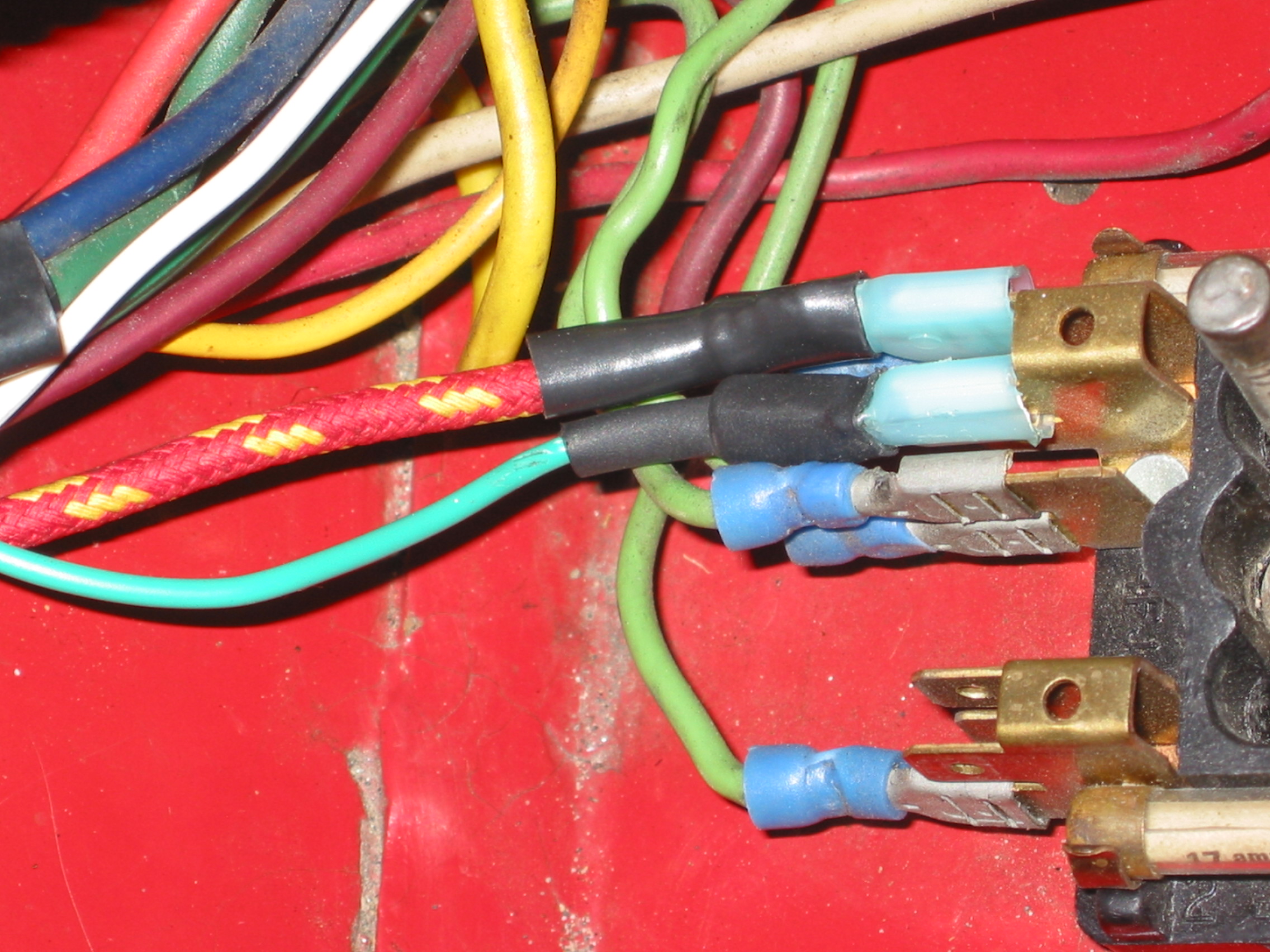
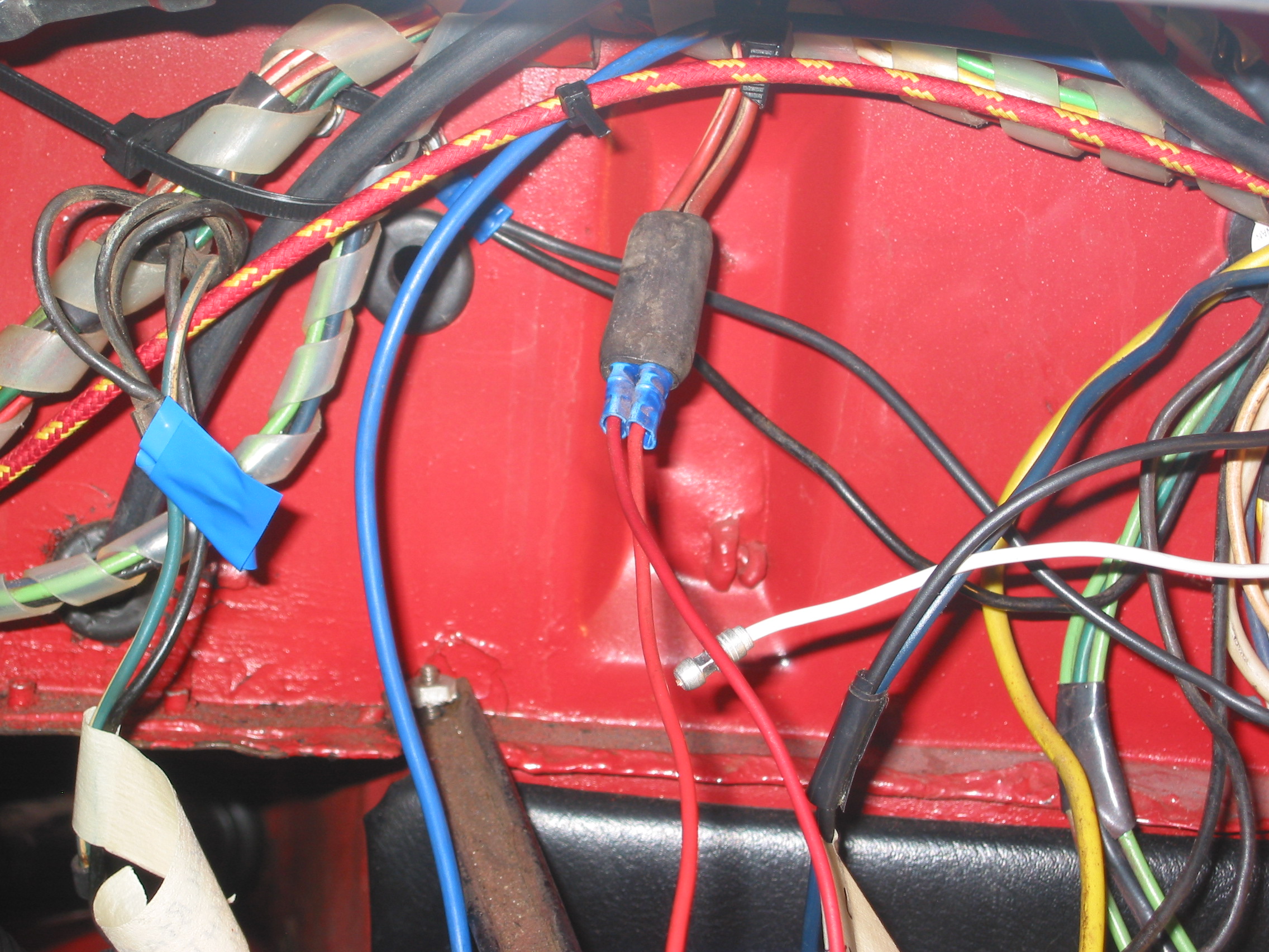
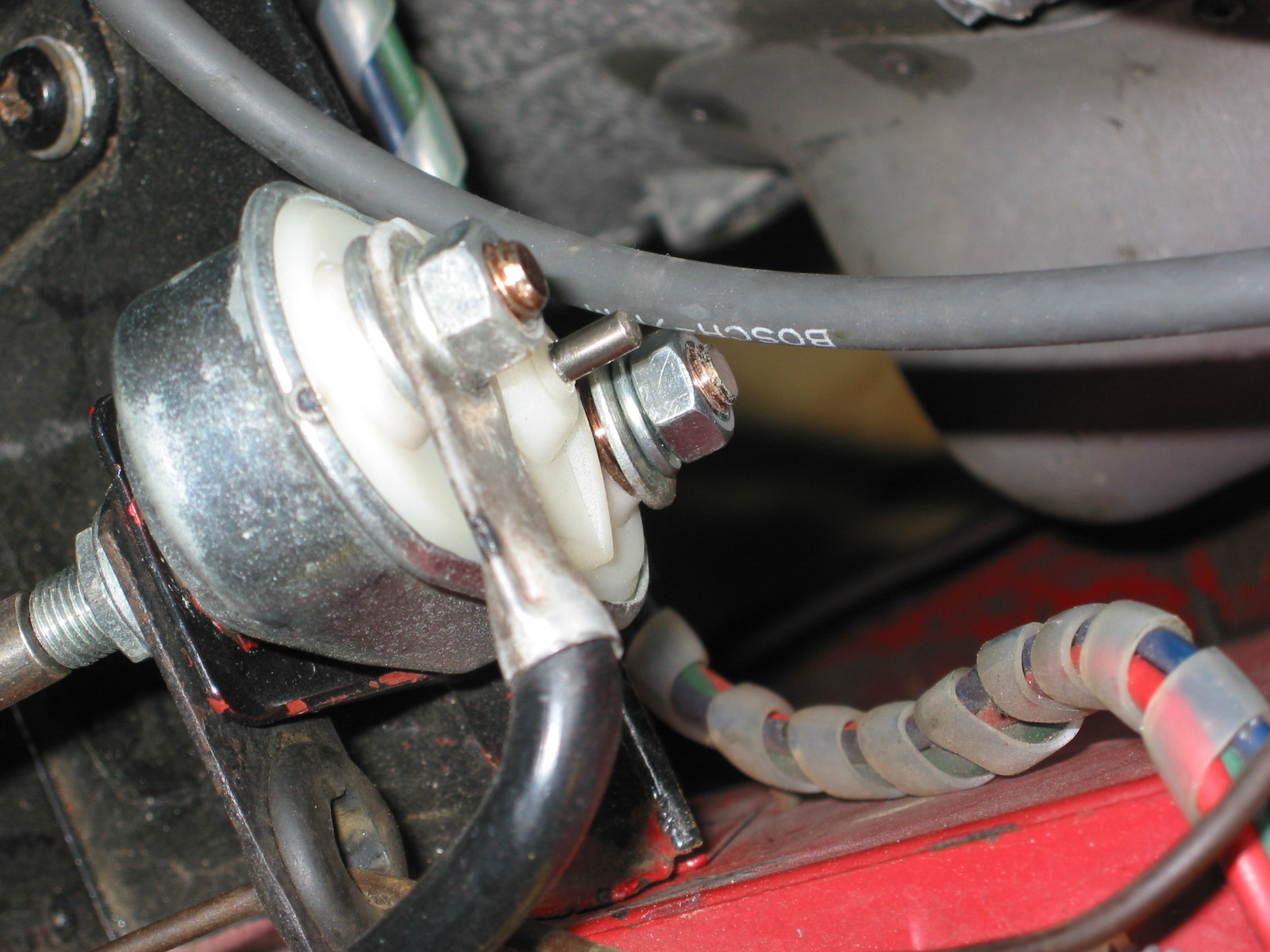
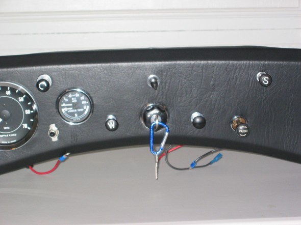
The Ignition Switch followed. The switch had four screw terminals. The top right terminal had 2 red wires joined together. The top left terminal had 1 heavy gauge yellow wire. The bottom right terminal had two white wires joined together and an red fused wire from the the electric fan switch that had been added. Finally, a large blue wire was disconnected the bottom left terminal. A previous owner had fabricated a clamping system to hold the ignition switch in place, that while primitive, did work. It will be replaced later.

Ignition Switch Wiring
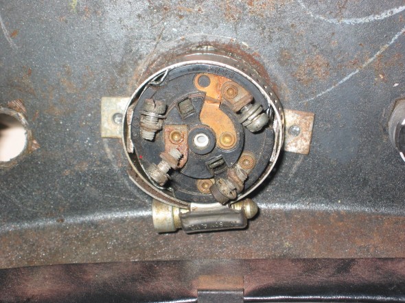
Ignition Switch
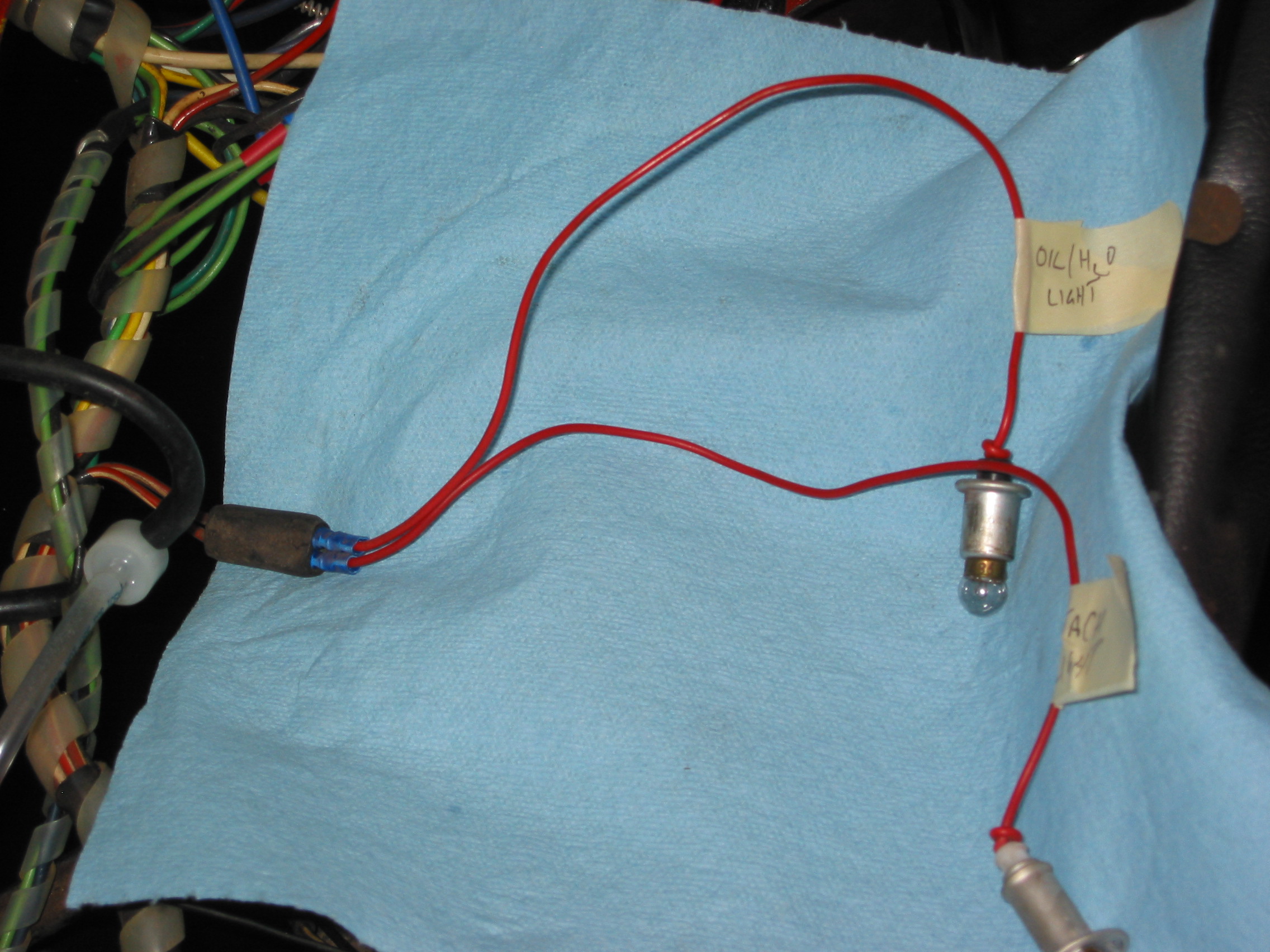
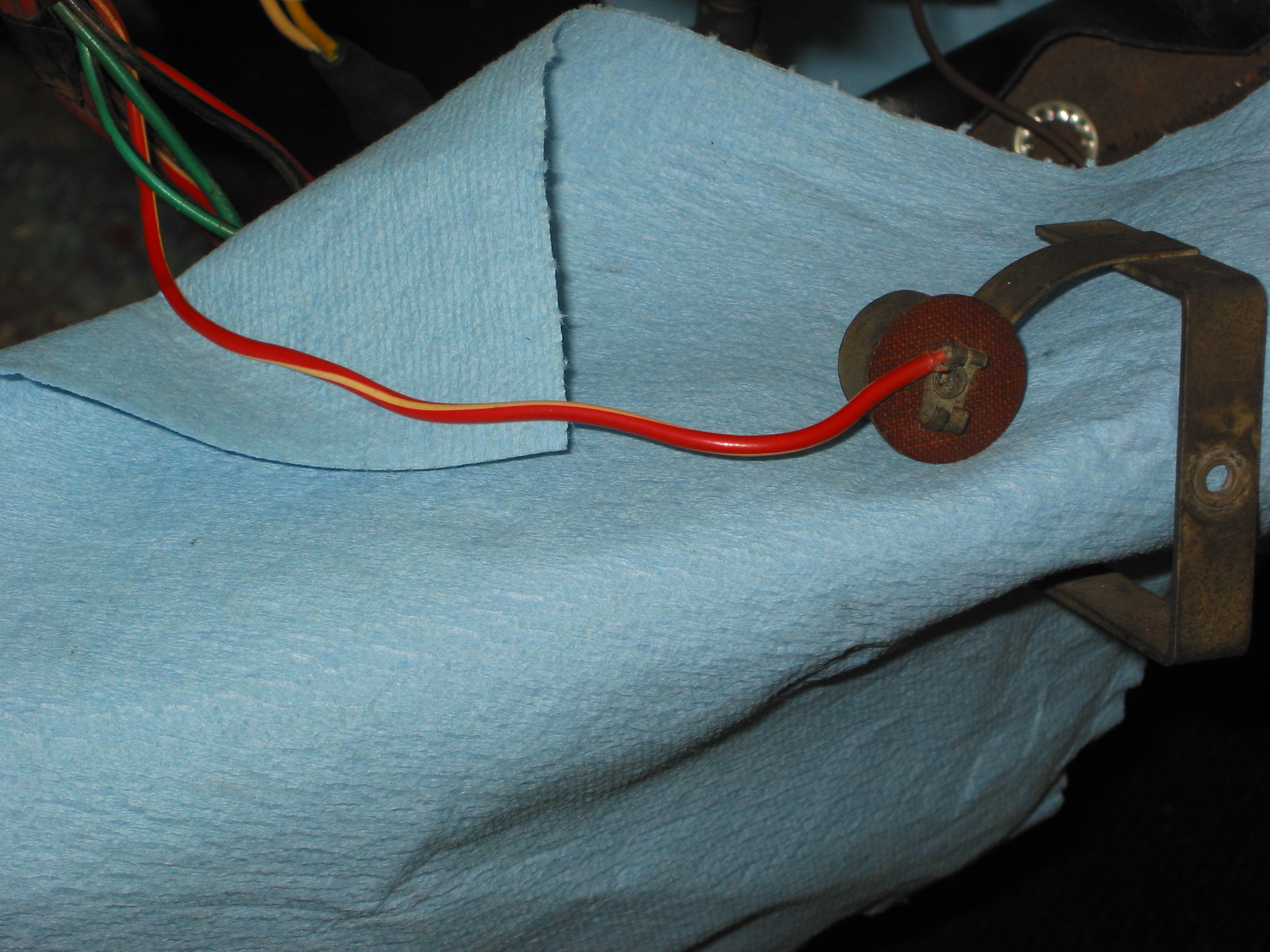
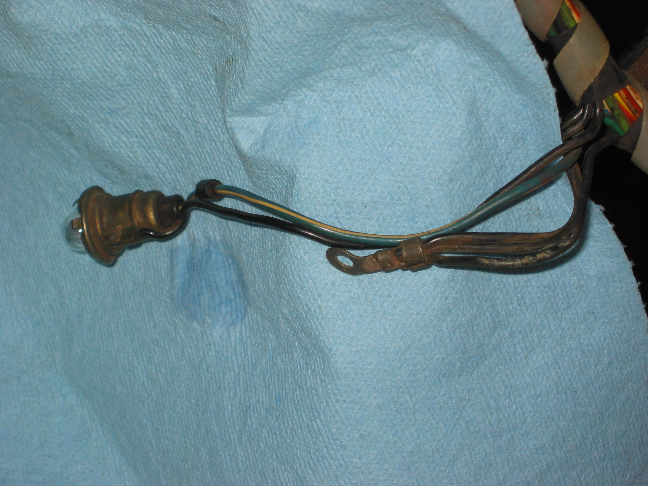
Gauge Lights. Wiring for most gauges is red. The oil/water temperature gauge light fit into the retaining bracket sleeve. The tach light was also red, but this wire was ultimately discarded as it was not needed for the lighting for the new tach.
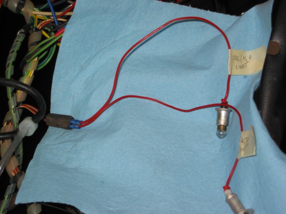
Oil and Tach Lighting

Oil & Water Temp

Tach Lamp Wiring
Speedometer Lamp Wiring
Wiper Switch. Disconnected the dark blue wire with a soldered tip from the right screw terminal, and the black wire from the left terminal.
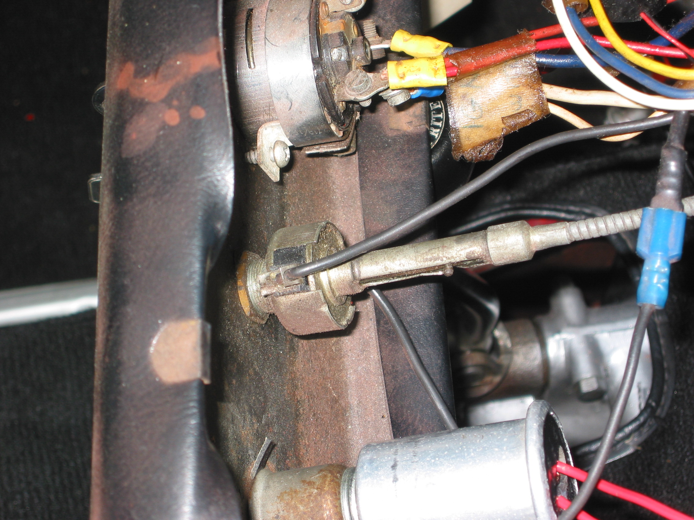
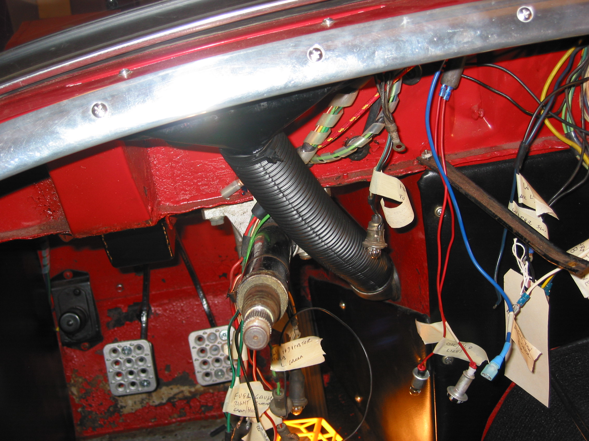
Fuel Gauge wiring. One black ground wire was removed from the retaining bracket. A red/white wire for the lamp to the retaining bracket, a green wire to the left terminal and a green/black wire to the right terminal were all disconnected.
Fuel Gauge Wiring
Panel Lamp Switch.
The panel lamp switch had three wires. Two red/white wires were joined and connected to the right terminal and 1 red wire was disconnected from the left terminal.

Panel Lamp Switch

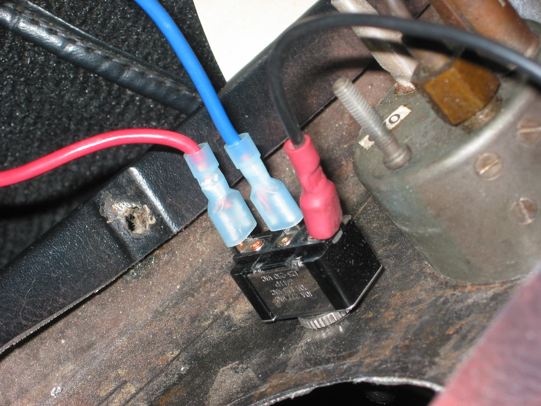
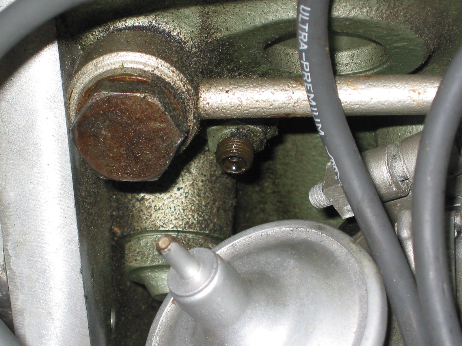
Radiator Fan Switch
The radiator electric fan switch
Has three wires: the black ground wire was removed from the top spade terminal, the blue power wire from the switch to the fan itself was removed from the middle spade and the red wire with fuse to the ignition was also disconnected.
The Horn
Had one brown wire from the horn trim ring to the horn itself. The wire was disconnected at the bullet connector.
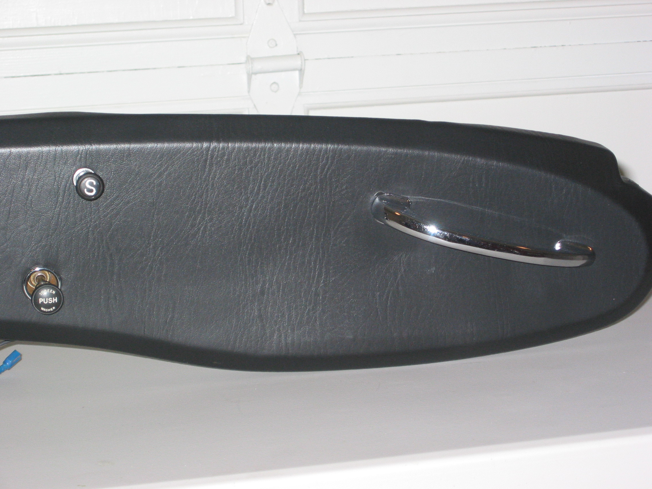
After removing the starter button and cable, the choke cable and the heater air control assembly cable, and the grab handle, the dash was removed from the car. Two ¼” hex head bolts secured the dash to the body on the left and right side. Two chrome phillips head screws fastened through two brackets from the firewall to the dash and finally one nut is fastened to a stud located centrally at the top of the dash.
Recovered Dash
Then it was time to recover the dash. I purchased some naugahyde at a local fabrics store and some contact cement and went to work. This is the result:
Fresh New Look
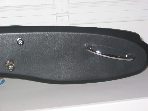
Reupholstered Dash
Horn Ring
Reupholstered Dash
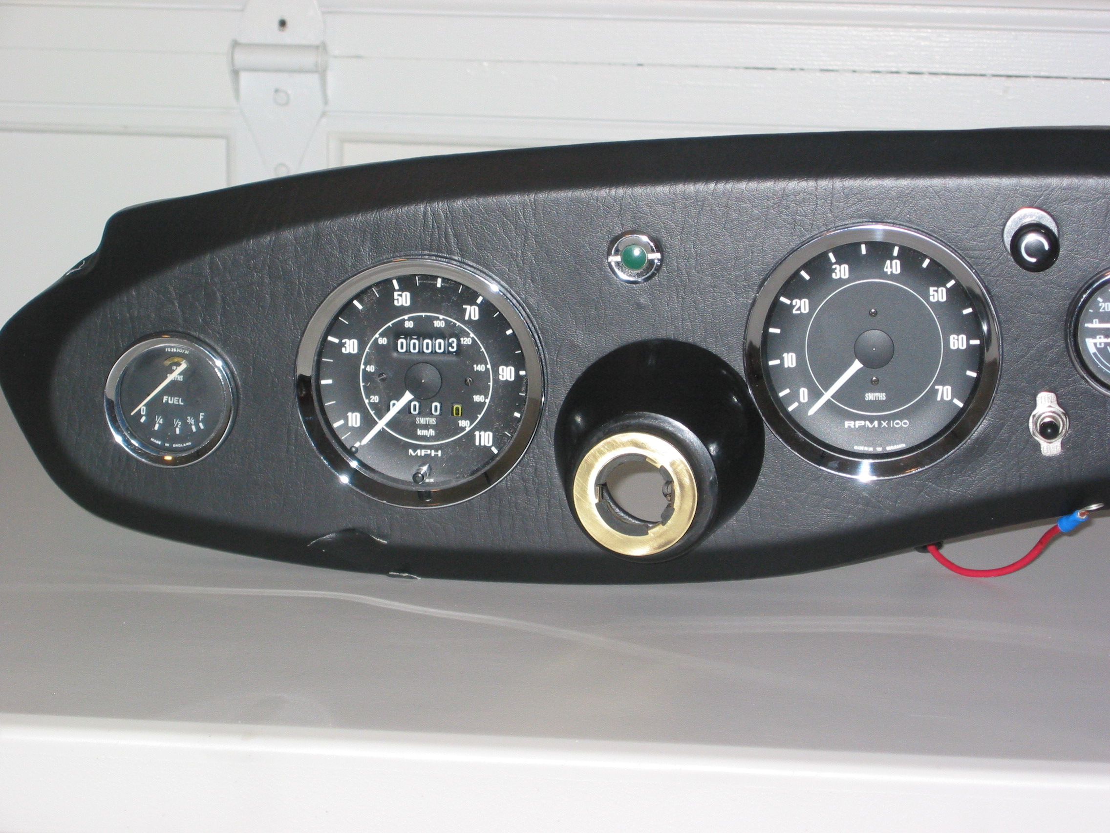
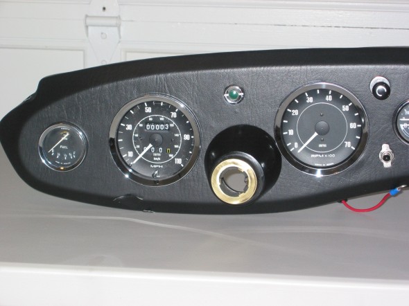
The new tach and speedometer
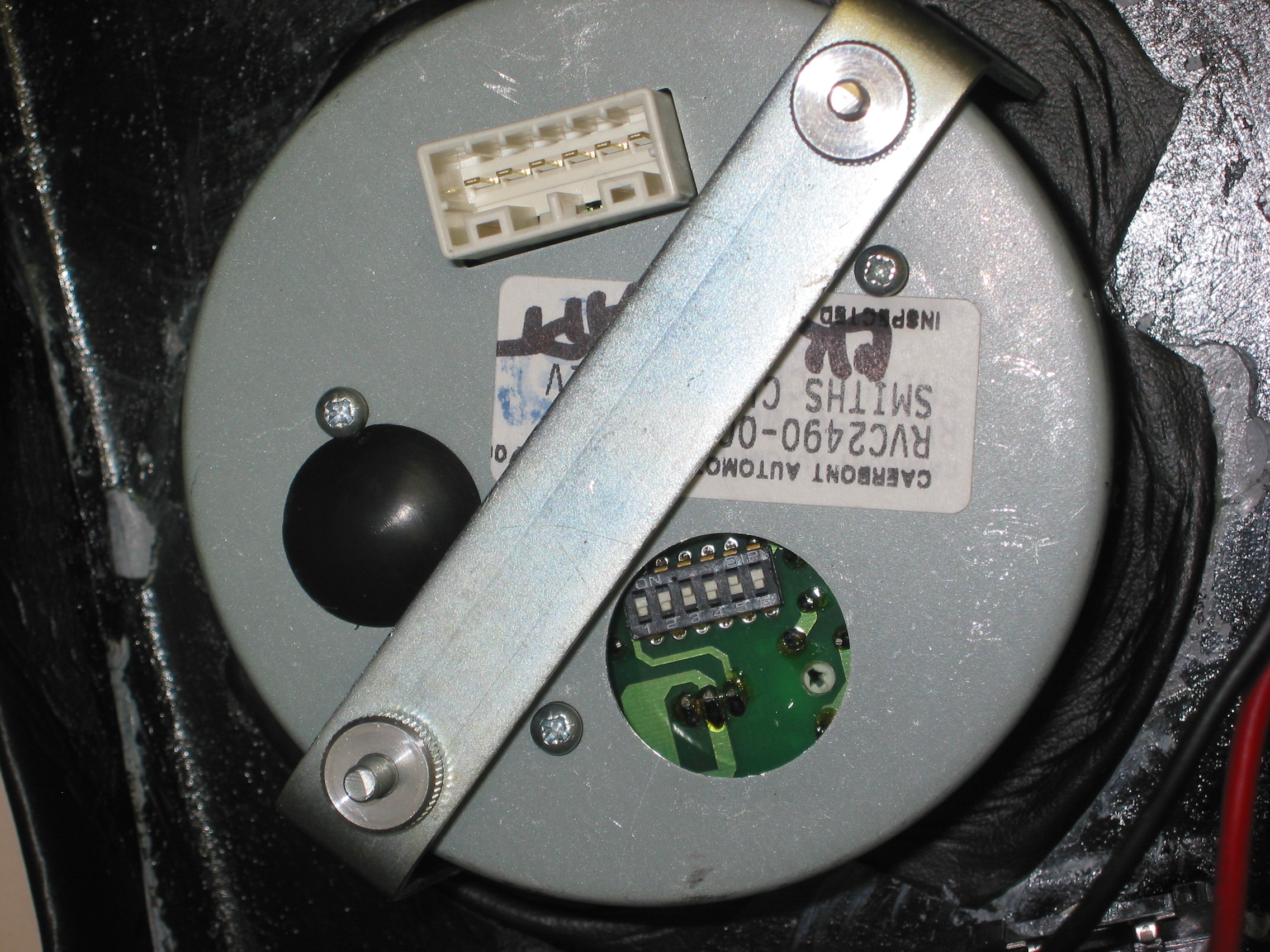
While not original design, the new tach certainly looks period. The tach required some new electrical connections. One wire connected to the coil, another to the fused power block and one to ground. These are the installation instructions:Electronic Tachometer Installation Instructions
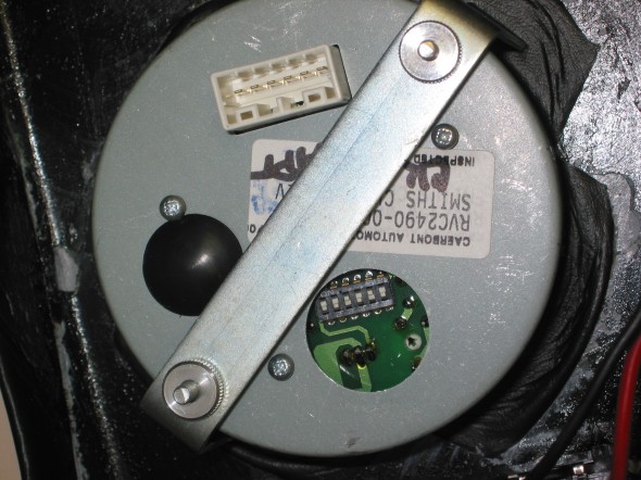
Smiths Electronic Tach
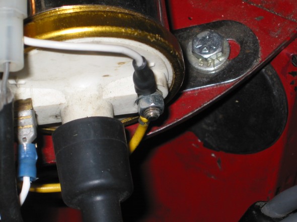
tach coil connection

Tach Fused Power
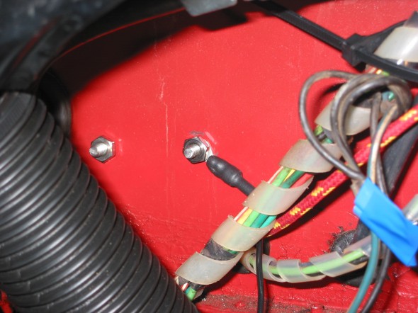
Tach Ground

Coil White Wire
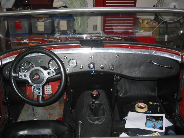
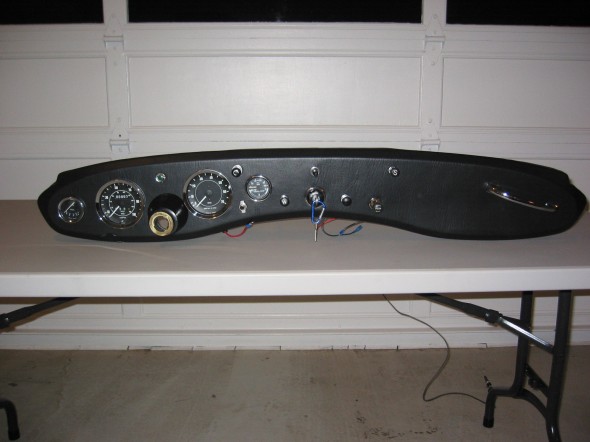
Finished Dash Installed
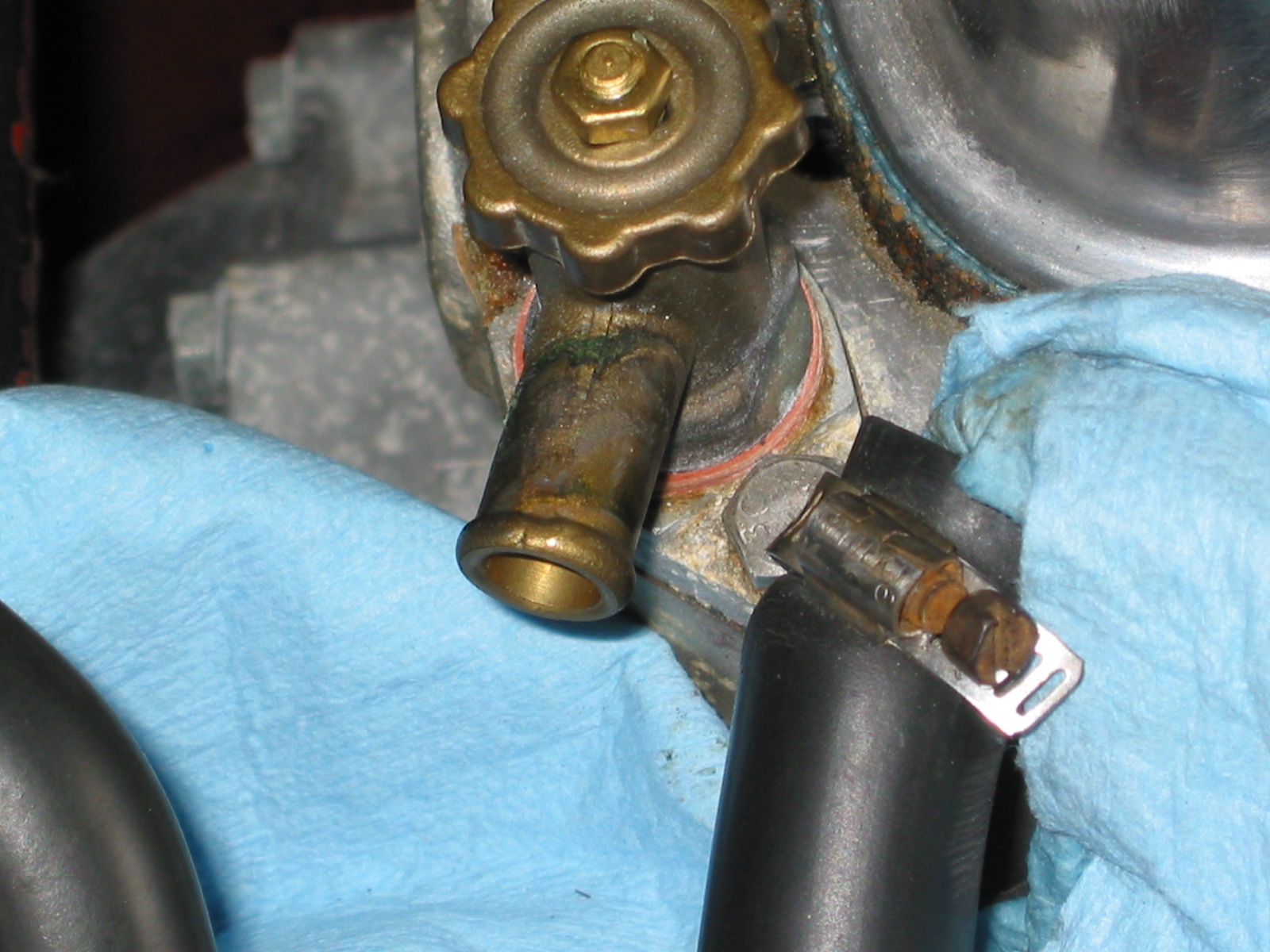
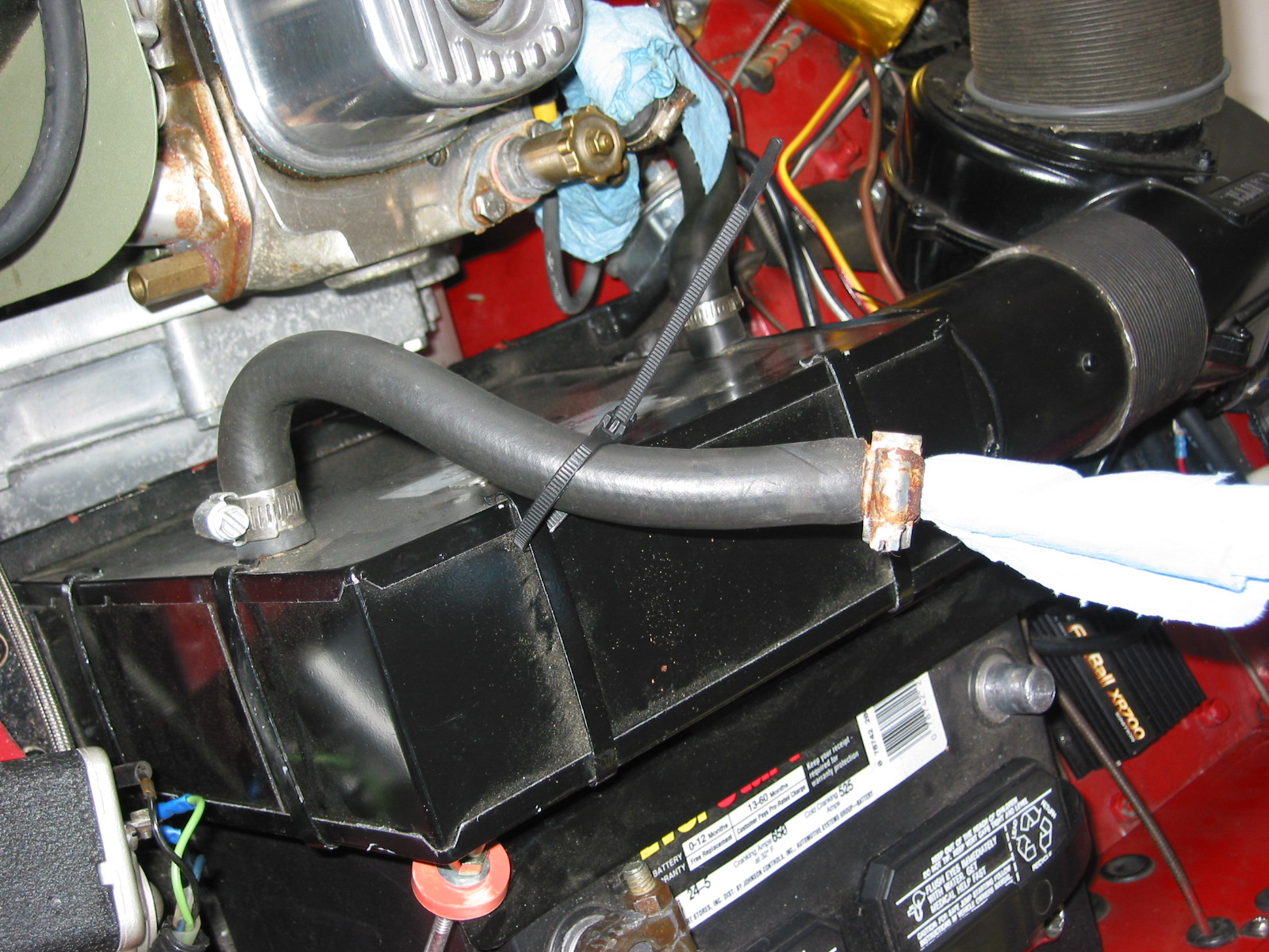
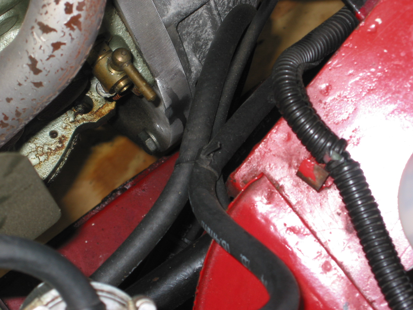
Demister Hoses
The old paper demister hoses had holes in them and obviously did not work well. With the dash off it was the perfect time to install some new hoses.

Left Side Hose
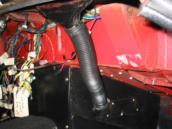
Right Side Hose
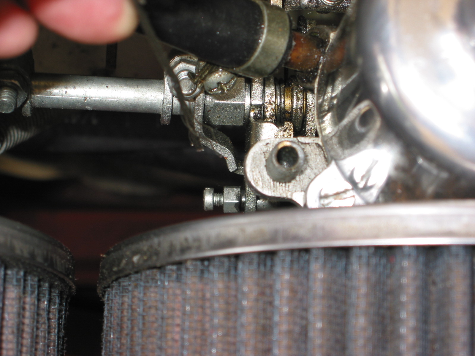
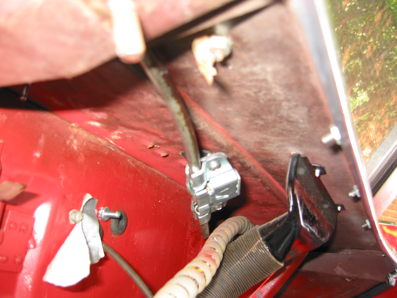
Aluminum Racing Pedals
My dad had installed racing pedals in the Big Healey and thought they did give a better pedal feel in addition to looking cool, so I bought a set for the Bugeye as well. They do look nice. I did not use the racing pedal for the accelerator pedal as it was just too close to the brake.