
Wiring System Upgrade
The Fuse/Relay Panel
The heart of the original Jaguar MK2 electrical system was a fuse panel assembly located on the LH engine bay valance under the bonnet. The fuse panel bracket assembly houses the RB310 Voltage Control Box (Regulator), the Fuse Box unit, and the Horn Relay. It has a metal top protecting the internal components which is secured by a knurled chrome thumb screw or knob. My panel was pretty rusty but cleaned up nicely with media blasting and was then powder coated black.
Today it is hard to imagine that the fusing of the entire electrical system of the car was handled by two fuses!
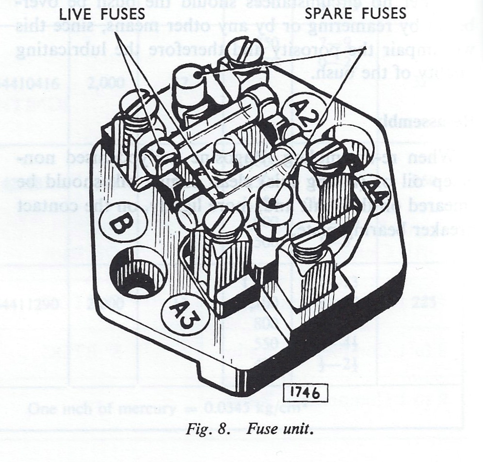
Fuse Unit
I am upgrading the electrical system and will be using an alternator with an internal regulator to replace the dynamo or generator. This action will eliminate the need for the voltage control box. I will use a modern Bosch automotive relay for the horns which will eliminate the need for the original Lucas horn relay. Finally, I am upgrading from the original Model SF6 fuse unit with the two glass fuses of 35 amps and 50 amps to a modern fuse/relay panel supplied by Marc Goldblatt, owner of Classic Technologies. http://www.classic-technologies.com I will be able to utilize the base of the original fuse panel bracket assembly with Marc’s fuse/relay panel and will therefore keep the fuse connections at the same location as original to the car. Marc’s panel can be mounted horizontally or vertically and I will not make a final decision on the orientation until I have the engine in place for trial fitting.
This is a link to a short video that Marc Goldblatt made about his product.
The Classic Technologies fuse/relay panel provides for 15 fused circuits with 34 pin connectors, 7 relays including horn, ignition power, fog lights, high beams and low beams headlights, starter and accessory power and 2 flashers for the turn signals and hazard lights. I selected the optional relays for LED lights.

Classic Technologies Relay Fuse Panel
The new harness is simplified and made up of discrete runs from the fuse box to the switch or accessory. The enclosure for the fuse box is 16 gauge steel with a powder coated finish that is silk screened for easy identification of the fuses, relays and terminations. The Classic Technologies panel is only 6 3/4″ (171mm) long X 4 5/8″ (81mm) wide X 2 3/16″ (56mm) tall. The lug-less terminations into unpluggable connectors are another nice feature making the installation of the panel easy and convenient.
A poster size color schematic was provided along with a clear instruction manual to guide hobbyists like myself through the installation. Marc will provide additional support if needed.
This is the original assembly:
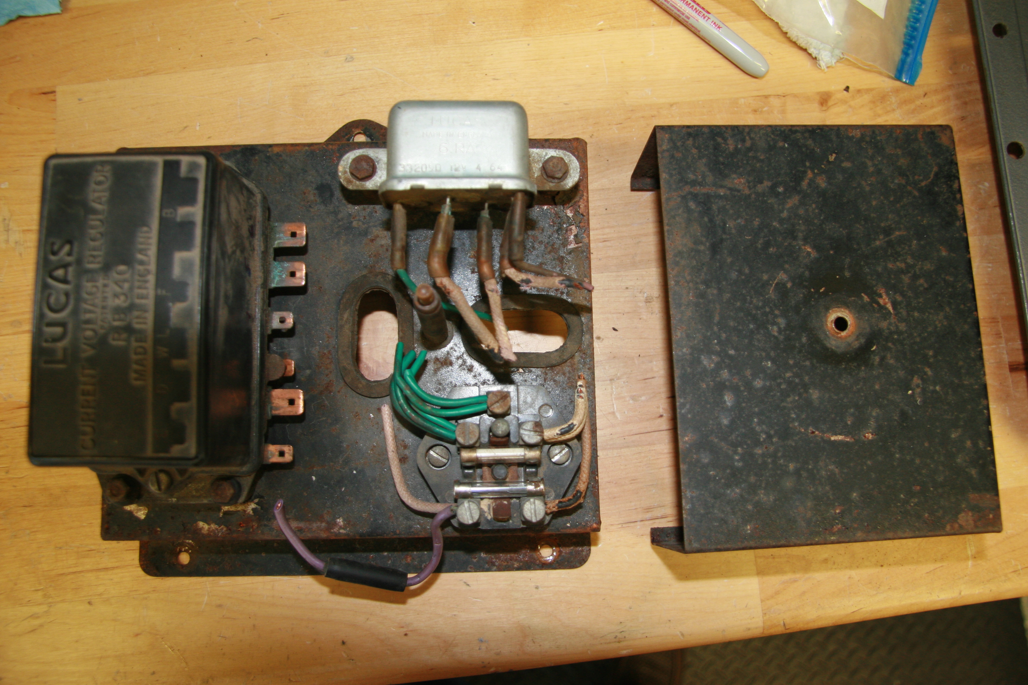
Bracket Assembly, Mounting Horn Realy, Fuse and Control Boxes
Although the Classic Technologies Box is more often seen mounted under the bonnet somewhere, I have elected to mount it under the dash on the RH side of the interior. This will require some modification of the fiberboard panel under the dash but that should be accomplished with little problem. My installation looks like this:

Mounting of the Classic Technologies Fuse Panel
I will still use the base of the original fuse panel bracket assembly in its original location on the LH valance in the engine bay. Three Barrier terminal blocks used to make connections for lights, horns and etc., will be mounted on the LH valance and the base of the fuse bracket will be used to cover and protect the terminal blocks and wiring. On the top of the base I will be mounting fuses and connectors associated with the alternator, and power steering. I will then fabricate a new cover for the base that will shield the entire base not just 2/3 of it as was done originally. This is the powder coated mounting bracket assembly:

Powder Coated Fuse Panel Bracket Assembly
Fuse/Relay Panel Design Theory
The 15 fuses are broken up into three groups:
1. Constant Power: Fuses F1 through F4, F8, and F15. These fuses are tied to the battery + terminal (B+). Examples: Dome Lights, Parking Lights, Hazard Flashers, and Horn. These features have power regardless of ignition switch position.
2. Ignition Power: Fuses F5, F6, and F7. These are items that are critical to starting the car that should have power while the car is being started. Examples: Coil, Alternator excitation, Fuel Pump, Gauges/Warning Lights, brake lights.
3. Accessory Power: Fuses F 9 through F14. These are items that are not critical to starting the car and should not have power while starting the car to maximize power to the starter. Additionally, in order to prevent battery drain, these items should not have power when the keys are removed from the ignition. Examples: wipers, heater motor, turn signals, overdrive, radiator fan, radio, reverse lights…
New Wiring System Requirements
In addition to the gauges, switches, and components typical of the MK2 that the Classic Technologies Fuse/Relay Panel would manage, the modifications to my car will necessitate individualizing the wiring schematic that Marc provides with his panel kit.
I will need to add circuitry for the following features:
Air Conditioning
My car was not air conditioned originally. I am installing an after-market kit produced and sold by Rock Browning of RetroAir, Inc. As I see it, the kit has the following electrical components that will need to be incorporated into the new wiring diagram.
SPAL 12” Electric Radiator Fan – 5.3 amps
Water temp sender to cut fan on/off Circuit breaker
Fan relay
Trinary switch
Compressor relay
SPAL 3 speed Blower Fan to circulate air – 16 amps max
Control panel switches – 3 speed fan switch, temperature switch
Power Steering Pump
My car did not have power steering originally although it was an option at the time. I have installed rack and pinion from a later Jaguar that uses an electric power steering pump. The vendor, M&C Wilkinson reported “The power steering pump uses approximately 40 amps at maximum draw which is slow speed/full lock.”The vendor also supplied an 80 amp fuse and a connector block.
Upgraded Wiper System
I am using a more recent Jaguar wiper motor and a modified wiper switch all purchased from Classic Motor Cars in England. I understand the amperage requirement to be 6 amps.
Power Front Seats
I am using seats from a later Jaguar (1990 Daimler XJ40). Although the seats have heaters, memory and a few other gadgets such as a seat belt alarm, I intend to only use the seat motion adjustments (four switches for each seat that will be mounted on the central console), and the lamps on the rear of the front seat headrests. The back of the seats have folding “picnic” tables.
Looks like the seats require 5 amps (7.5 max) each. Each seat needs a relay.
Sound System Amplification
Specifications for the amplifier have yet to be determined, but I anticipate perhaps a 300 watt amplifier requiring approximately 25 amps.
Accessory Power Outlets
Redundant Fuel Pump
Third Brake Light
Back-up Camera
Headlight Warning Chime
British Wiring Codes
I plan to stick with British Wiring Codes wherever possible in the rewiring of the MK2.
Mike McPhail, the president of the South Texas Austin-Healey Club, published an article in the July, 2010 issue of Regional Rumblings, the Club’s newsletter that provided an excellent color coded summary of Lucas wiring that will surely prove helpful with the Jaguar as well.
Wiring System Upgrade
wow what a scary wiring system the mk2 used. over time the wiring harness aged and broke down, maybe because it was housed right beside the engine exhaust system.
another point to remember is the system is heavily taxed when a few large current drawing devises are switched on.
like the wiper motor which is located at the end of the 12 volt daisy chain.
over time this motor ages and draws more current to work, making the wiring run even hotter.
l’m really surprised more jagaur mk2 aren’t burning beside the roads
Will you get the CT harness kit as well or will you fix this on your own. I am asking as I will rewire an MK 2 myself in near future and wonder if CT kit is on the spot enough.
Kjell,
I am building my own harness. See my posts under https://valvechatter.com/?p=7274
I really like the CT relay/fuse panel and recommend it. I can be adapted to an original type harness as well.
Lin
Ahh should have read it all. Now I just jumped in from a google search on Classic Technologies. Looking forward to read it all.
Lin, This is great. Thank you. I will do something similar on my car. When I was looking at off the shelf harnesses available in Aust and NZ it seemed hard to get what I thought was needed.
Hi Phil,
Cannot recommend Marc Goldblatt’s Classic Technologies Relay/Fuse panel enough. Product is great and service is extraordinary. Eric Kriss also used it on his MK2 build. http://fairislepress.com/WP/?p=4311
This is a link to a video Marc made about his product.
https://youtu.be/0tYJZ-GlYwE
Lin
I have driven my MK2 daily in the Dallas area since 1996. I have had done many of the same upgrades as on your project. My powerplant is a late Series III XJ6 4.2L (rebuilt 1996) with Mustang Cobra 5 speed manual gearbox, with aluminum flywheel. I also have the XJ40 power front seats with headrests, rack and pinion power steering, LED tail lighting, under dash top rail ultraviolet, new wiring loom (2010), etc etc etc. I went with the Danhard a/c components in 1996 and mounted the condensor/fan in the left wheel well. It has performed well since… especially in Texas July’s-August’s but with all 4 center dash vents pointed at me… the AM radio was in that space and I went with an under dash AM/FM 10 CD Changer in 2001… which I don’t use much now that cell phones and ear buds arrived with music loaded or Pandora. Most of my restoration/upgrade work was done prior to backup cameras and great new things coming out now.
One thing I flunked on which you may not have gotten to yet is the alternator/pulley/fan belt setup. I “settled for” a Delco AD230 series alternator (105 amps rated) to accommodate very limited operating space up there and all the updated elec loads and a big a/c compressor from Vicarage. Getting the pulleys and fan belt setup was where I underwhelmed myself. The alternators now mostly have pulleys for wider serp belts and I needed to stick with a classic V belt for space. I’m finding out (I think) that my alternator belt wrap or belt/pulley config is causing some belt slippage when heavy loads (a/c, etc.) are applied and the alternator becomes more difficult to turn. Consequently I a recently noticed some troublingly (for me) low-like voltage dash gauge readings when simul operating a/c, lights, etc. At least that is my current theory. But anyway just saying that topic deserves more attention than I gave it when I was re-doing my engine bay (dammit!). happy to compare notes offline… good luck on your finished project, you are definitely going about it the right way IMO. Regards, scf
Sterling,
Great to hear from you, and happy to have someone who has travelled (traveling) down the same path. Thanks for your thoughts regarding the pulley set up. I will getting back to that subject soon. I am about 85-90% complete on the wiring and as soon as I have that complete I will return to the pulley situation.
So do you have only the one condenser in the wheel well, or is it a second condenser in addition to one in front of the radiator? Where is your evaporator? I would love to see some photos of your installed system if you have some you will share. I would also like to see your interior seat installation.
Really look forward to seeing your car. Thanks so much for reaching out!
Lin
Pingback: Jaguar wiring deconstructed – My test blog