
I should first note that at this point in time, the content of this post is incomplete. To complete the project I will need the assistance of other Alfa owners, and I expect that the help will be received over time rather than immediately.
Early in my work with my 1987 Quadrifoglio I decided to try to inventory all of the various type and size hose clamps used throughout the car, but primarily in the fuel, emissions and vacuum systems. I have used diagrams taken from the service manual as well as a narrative listing to identify the hose clamps and their location. The numbers added to the diagrams reflect the numbering sequence used in my narrative summary. What I identify in this post is current as of February 17, 2021.
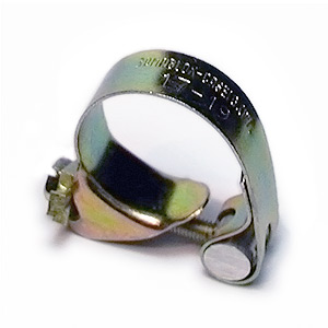
Romablok clamp
The hose clamps used by Alfa-Romeo were manufactured by Romablok, but they are no longer made. The feature of these clamps that is important to maintain is that they wrap all the way around the hose and tighten 360 degrees. The also have a smoother outside edge with an external screw and a flat solid band so as to not cut into the hose.
I began my effort by visually inspecting the engine bay and then moved to the trunk and then finally under the car.
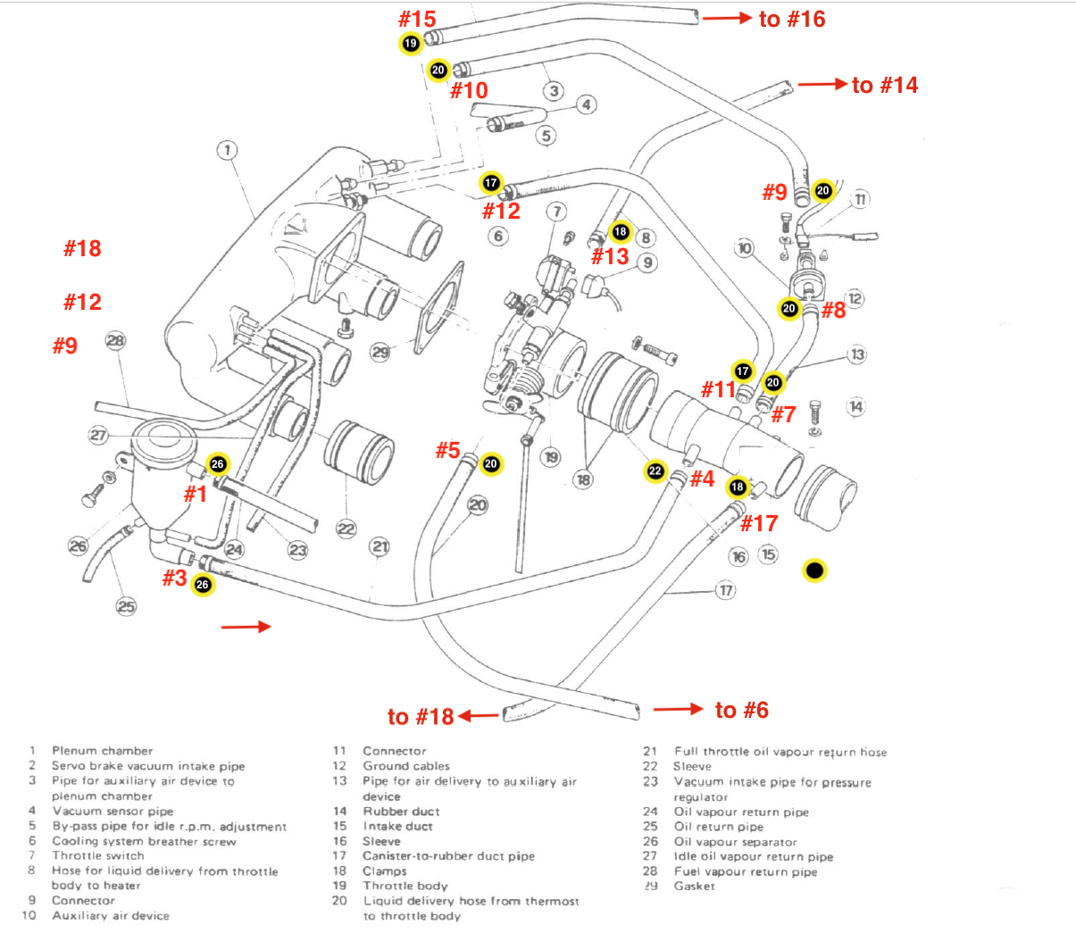
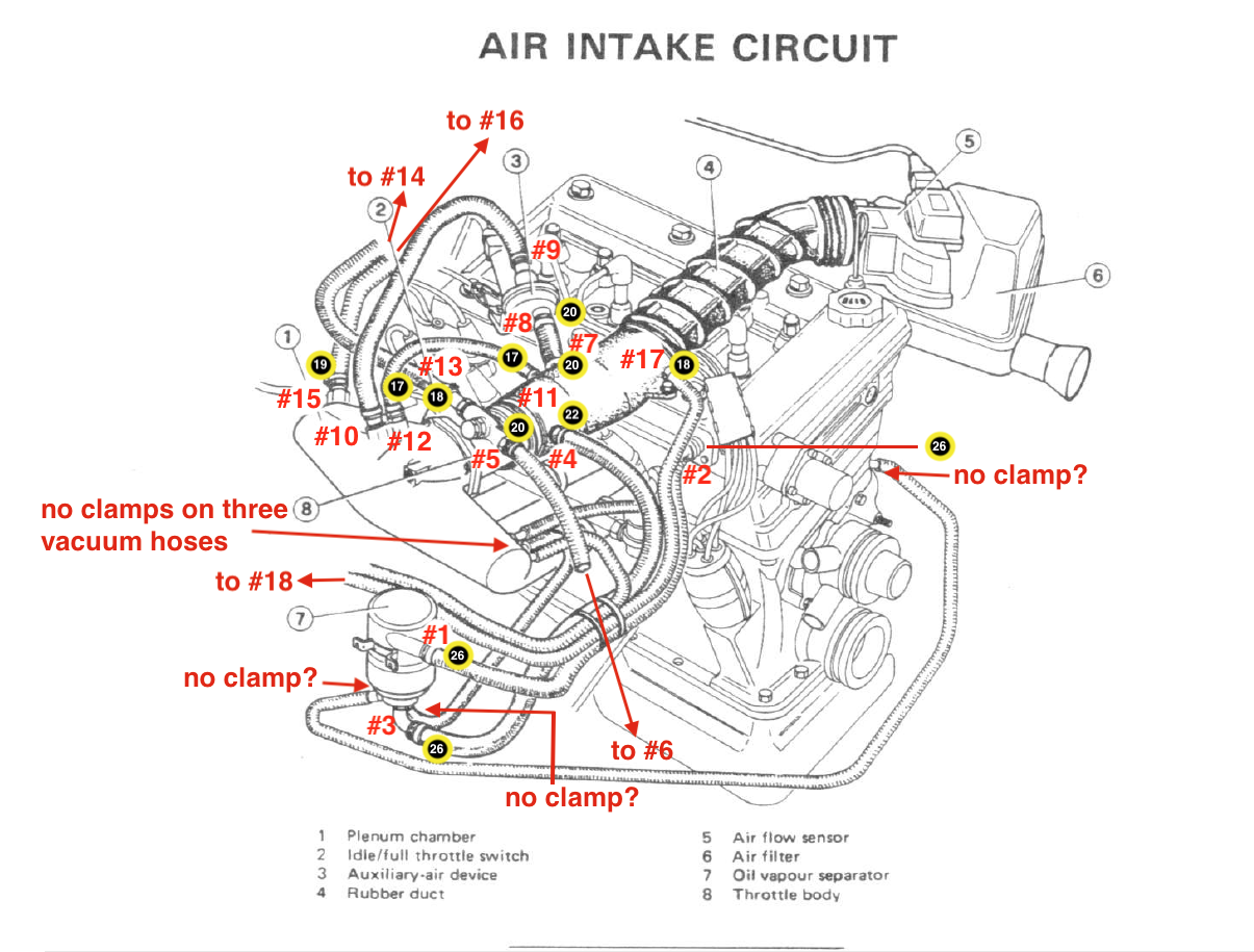
OVS upper port clamp #1 (26) to cam cover breather fitting clamp #2 (26)
OVS large lower port clamp #3 (26) to the rubber air duct clamp #4 (22)
Throttle body clamp #5 (20) to the thermostat clamp #6 (20)
Rubber air duct clamp #7 (20) to the AAV clamp #8 (20)
AAV clamp #9 (20) to the plenum chamber clamp #10 (20)
Rubber air duct clamp #11 (17) to the plenum chamber clamp #12 (17)
Throttle body clamp #13 (18) to the heater water valve clamp #14 (?)
Check valve at plenum chamber clamp #15 (19) to the brake booster clamp #16 (19)
Rubber air duct clamp #17(20) to the canister clamp #18 (?)
Fuel filler upper clamp #19 (66) to fuel filler lower clamp #20 (66)
Fuel Delivery from tank to fuel rail
A rubber fuel hose from the secondary fuel pump connects with clamp #21 (15-17) to a fuel hard pipe in the trunk with clamp #22 (15-17). The fuel hard pipe passes through the rear trunk bulkhead to a 3-4” piece of rubber fuel hose and is clamped with #23 (15-17). This short rubber fuel hose connects to another hard pipe with clamp #24 (15-17). This fuel hard pipe is covered with a rubber fuel hose as a sheath for the metal pipe.
The fuel hard pipe runs along the underside of the car toward the fuel pump. The covered fuel hard pipe is connected to a rubber fuel hose with clamp #25 (?). The rubber fuel hose, configured in the shape of an “S” connects to the input port on the fuel pump with clamp #26 (?). A rubber fuel hose connects to the output port on the fuel pump with clamp #27 (12-14), travels to the fuel filter input port and is connected with clamp #28 (12-14). The same size rubber fuel hose connects to the output port of the fuel filter with clamp #29 (12-14) and connects to the fuel hard pipe (encased in a rubber sheath) with clamp # 30 (12-14) that is directed along the frame rail to the engine bay and to the fuel injector rail where it is secured with clamp #31 (12-14). A short rubber fuel hose from the fuel injector rail secured with clamp #32 (12-14) connects to the cold start injector and is secured with clamp #33 (12-14).
Fuel Return to Tank
A rubber fuel hose from the fuel pressure regulator with clamp #34 (12-14) to rubber fuel hose that travels under the car to a junction with a fuel return hard pipe covered with a rubber sheath. The hose is secured with clamp #35 (12-14) on the engine side and with clamp #36 (12-14) on the rear axle side. The pipe then travels over the axle to the rear trunk bulkhead where it is joined by clamp #37 (12-14) to a three inch piece of rubber fuel hose. The other end of the short piece of hose is clamped #38 (12-14) to the fuel return hard pipe that exits through the bulkhead into the trunk. The fuel hard pipe runs along the back of the trunk where it joins with a rubber fuel hose with clamp #39 (12-14). The rubber fuel hose terminates at the return pipe fitting on the fuel tank and is secured with clamp # 40 (12-14).
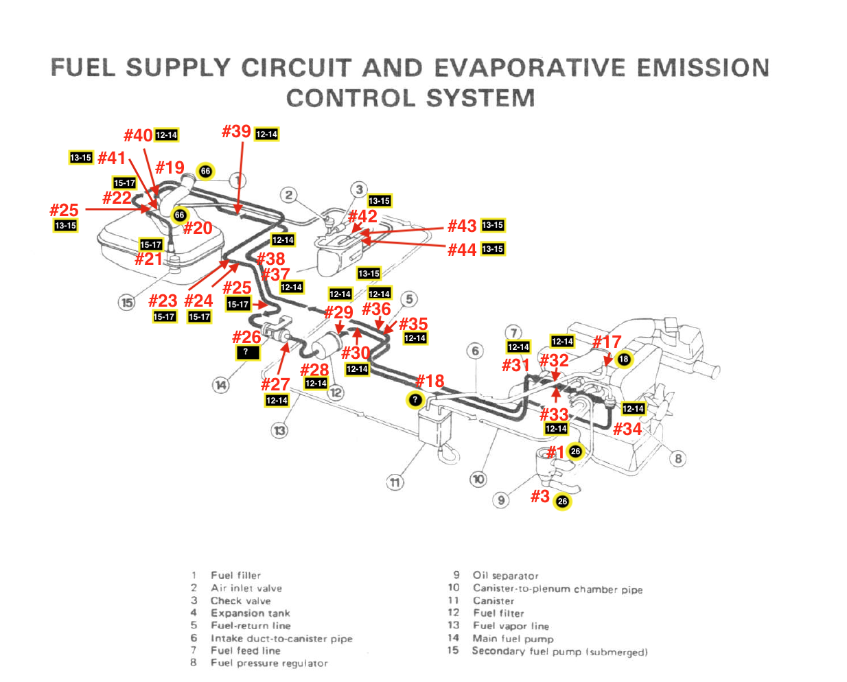
Fuel Supply Circuit & Evaporative Emission Control System
Plenum Chamber
Evaporative emission control system
Clamp #41 (13-15) secures a rubber fuel hose to the evaporative emission outlet pipe at the fuel tank. The hose routes to the rear of the trunk where it connects to the LH lower side of the expansion tank with clamp #42 (13-15).
A rubber emissions hose exits the expansion tank on the LH upper side and is reduced to a smaller diameter rubber hose. The two hoses are connected with two clamps: clamp #43 (13-15) and clamp #44 (13-15).
The smaller diameter hose wraps around the expansion tank and joins a “T” fitting with no clamps. A vent valve is joined at the “T.” The smaller hose then merges with a larger hose with a check valve and then rejoins with a smaller rubber hose and then a still smaller clear hose that seems to exit the trunk behind the LH rear shock absorber. I don’t know where it goes. There is also a fairly large diameter black hose in the same location. I don’t know what it does or where it goes.
I did not open the panel in the front RH wheel well to inspect the charcoal canister. The clear hose connects with the canister. I do not know if it uses a clamp or not, but I will call it clamp #45 (?). As stated earlier, a rubber hose feeds air from the rubber air duct #17(20) to the canister #18 (?). The intake air duct feeds air to the canister via a rubber hose with clamp #46 (?) at the canister and clamp #47 (?) at the air duct fitting.
Cooling system
I need to finish looking at these.